Page is loading ...

3-CCD Color Camera
MODEL HV-F31F
HV-F22F
OPERATION MANUAL
Please read this operation manual carefully for proper operation, and keep it for future reference.
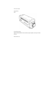
Note: The model and serial numbers of your product are important for you to keep for your convenience and
protection. These numbers appear on the nameplate located on the bottom of the product. Please record these
numbers in the spaces provided below, and retain this manual for future reference.
Model No. Serial No.
Hitachi Kokusai Electric Inc.

A
IMPORTANT SAFETY INSTRUCTIONS
1. Read Instructions
All the safety and operating instructions should
be read before the product is operated.
2. Retain Instructions
The safety and operating instructions should be
retained for future reference.
3. Heed Warnings
All warnings on the product and the operating
instructions should be adhered to.
4. Follow Instructions
All operating and use instructions should be
followed.
5. Cleaning
Unplug this product from the wall outlet before
cleaning. Do not use liquid cleaners or aerosol
cleaners. Use a damp cloth for cleaning.
6. Attachments
Do not use attachments not recommended by the
product manufacturer as they may cause
hazards.
7. Water and Moisture
Do not use this product near water - for example,
near a bath tub, wash bowl, kitchen sink, or
laundry tub; in a wet basement; or near a
swimming pool; and the like.
8. Accessories
Do not place this product on an unstable cart,
stand, tripod, bracket, or table. The product may
fall, causing serious injury to a child or adult, and
serious damage to the product. Use only with a
cart, stand, tripod, bracket, or table recommended
by the manufacturer, or sold with the product.
Any mounting of the product should follow the
manufacturer's instructions, and should use a
mounting accessory recommended by the
manufacturer.
9. Moving
A product and cart combination should be moved
with care.
Quick stops, excessive force, and uneven surfaces
may cause the product and cart combination to
overturn.
10. Ventilation
Slots and openings in the cabinet are provided for
ventilation and to ensure reliable operation of the
product and to protect it from overheating, and
these openings must not be blocked or covered.
The openings should never be blocked by placing
the product on a bed, sofa, rug, or other similar
surface. This product should not be placed in a

B
built-in installation such as a bookcase or rack
unless proper ventilation is provided or the
manufacturer's instructions have been adhered
to.
11. Power Sources
This product should be operated only from the
type of power source indicated on the marking
label. If you are not sure of the type of power
supply to your home, consult your product dealer
or local power company. For products intended
to operate from battery power, or other sources,
refer to the operating instructions.
12. Grounding or Polarization
This product is equipped with a three-wire
grounding-type plug a plug having a third
(grounding) pin. This plug will only fit into a
grounding-type power outlet. This is a safety
feature. If you are unable to insert the plug into
the outlet, contact your electrician to replace
your obsolete outlet. Do not defeat the safety
purpose of the grounding-type plug.
13. Power-Cord Protection
Power-supply cords should be routed to that they
are not likely to be walked on or pinched by items
placed upon or against them, paying particular
attention to cords at plug, convenience
receptacles, and the point where they exit from
the product.
14. Lightning
For added protection for this product during a
lightning storm, or when it is left unattended and
unused for long periods of time, unplug it from
the wall outlet. This will prevent damage to the
product due to lightning and power-line surges.
15. Overloading
Do not overload wall outlets, extension cords or
integral convenience receptacles as this can result
in a risk of fire or electric shock.
16. Object and Liquid Entry
Never push objects of any kind into this product
through openings as they may touch dangerous
voltage points or short-out parts that could result
in a fire or electric shock. Never spill liquid of
any kind on the product.
17. Inflammable and Explosive Substance
Avoid using this product where there are gases,
and also where there are inflammable and
explosive substances in the immediate vicinity.
18. Heavy Shock or Vibration
When carrying this product around, do not subject
the product to heavy shock or vibration.

C
19. Servicing
Do not attempt to service this product yourself as
opening or removing covers may expose you to
dangerous voltage or other hazards. Refer all
servicing to qualified service personnel.
20. Damage Requiring Service
Unplug this product from the wall outlet and
refer servicing to qualified service personnel
under the following conditions:
a.When the power-supply cord or plug is
damaged.
b.If liquid has been spilled, or objects have fallen
into the product.
c. If the product has been exposed to rain or
water.
d.If the product does not operate normally by
following the operating instructions. Adjust
only those controls that are covered by the
operating instructions as an improper
adjustment of other controls may result in
damage and will often require extensive work
by a qualified technician to restore the product
to its normal operation.
e. If the product has been dropped or damaged in
any way.
f. When the product exhibits a distinct change in
performance-this indicates a need for service.
21. Replacement Parts
When replacement parts are required, be sure the
service technician has used replacement parts
specified by the manufacturer or have the same
characteristics as the original part.
Unauthorized substitutions may result in fire,
electric shock, or other hazards.
22. Safety Check
Upon completion of any service or repairs to this
product, ask the service technician to perform
safety checks to determine that the product is in
proper operating condition.
23. Wall or Ceiling Mounting
The product should be mounted to a wall or
ceiling only as recommended by the
manufacturer.
24. Heat
The product should be situated away from heat
sources such as radiators, heat registers, stoves,
or other products (including amplifiers) that
produce heat
.

L
IMPORTANT NOTICE
These products have been tested and found to
comply with the limits for a Class A digital
device, pursuant to Part 15 of the FCC Rules.
These limits are designed to provide
reasonable protection against harmful
interference when the equipment is operated
in a commercial environment. This
equipment generates, uses, and can radiate
radio frequency energy and, if not installed
and used in accordance with the instruction
manual, may cause harmful interference to
radio communications. Operation of this
product in a residential area is likely to cause
harmful interference in which case the user
will be required to correct the interference at
his own expense.
WARNING
Changes or modifications not expressly
approved by Hitachi Denshi responsible for
compliance could void the user’s authority to
operate the equipment.
This product does not exceed the class A/class
B limits for radio noise emissions from digital
apparatus as set out in the radio interference
regulations.
Le présent appareil n’émet pas de bruits
radioélectriques dépassant les limités
applicable aux appareils numériques de classe
A prescrites dans le rVglement sur le
brouillage radioélectrique édicter par le
ministére des communications du canada.
For USA For Canada

M
Table of contents
IMPORTANT SAFETY INSTRUCTUIONS
・・
A
IMPORTANT NOTICE
・・・・・・・・・・・・・・・・・・・
L
Table of contents
・・・・・・・・・・・・・・・・・・・・・・・・・
M
Standard composition
・・・・・・・・・・・・・・・・・・・・・
1
CD-ROM
・・・・・・・・・・・・・・・・・・・・・・・・・・・・・・・・・
1
Overview
・・・・・・・・・・・・・・・・・・・・・・・・・・・・・・・・
3
Features
・・・・・・・・・・・・・・・・・・・・・・・・・・・・・・・・・
3
Notes to users
・・・・・・・・・・・・・・・・・・・・・・・・・・・・
4
Important safety notes
・・・・・・・・・・・・・・・・・・・
4
Operating considerations
・・・・・・・・・・・・・・・・
4
CCD properties
・・・・・・・・・・・・・・・・・・・・・・・・・
5
System example
・・・・・・・・・・・・・・・・・・・・・・・・・・・
7
Section names and functions
・・・・・・・・・・・・・・・
8
Connectors
・・・・・・・・・・・・・・・・・・・・・・・・・・・・・・・
9
LENS
・・・・・・・・・・・・・・・・・・・・・・・・・・・・・・・・・・・
10
Camera mounting
・・・・・・・・・・・・・・・・・・・・・・・・
11
Control and status register (CSR)
・・・・・・・・・
12
IIDC standard CSR
・・・・・・・・・・・・・・・・・・・・・
13
Advanced CSR
・・・・・・・・・・・・・・・・・・・・・・・・・
20
Image color reproduction and
Color balance related CSR
・・・・・・・・・・
20
Image quality related CSR
・・・・・・・・・・・
24
Image level related CSR
・・・・・・・・・・・・・
28
CSR related to other functions
・・・・・・・
32
Specifications
・・・・・・・・・・・・・・・・・・・・・・・・・・・・
36
Input/Output Signals
・・・・・・・・・・・・・・・・・・・・・
38
Trigger operation and timing chart
HV-F31F
・・・・・・・・・・・・・・・・・・・・・・・・・・・・・・・・・
41
HV-F22F
・・・・・・・・・・・・・・・・・・・・・・・・・・・・・・・・・
43
External sync operation timing
・・・・・・・・・・・・
45
Dimensions
・・・・・・・・・・・・・・・・・・・・・・・・・・・・・・
46

1
Standard composition
Check when unpacking.
Camera HV-F31F/HV-F22F
・・・・・・・・・・・・・・・・・・・・・・・・・・・・・・・・・・・・・・・・・・・・・・・・・・・・・・・・・・・・・
1
DC IN/SYNC plug (HR10A-10P-12S)
・・・・・・・・・・・・・・・・・・・・・・・・・・・・・・・・・・・・・・・・・・・・・・・・・・
1
CD ROM (IIDC Driver and demonstration viewer software)
・・・・・・・・・・・・・・・・・・・・・・・・・・・
1
Operation manual
・・・・・・・・・・・・・・・・・・・・・・・・・・・・・・・・・・・・・・・・・・・・・・・・・・・・・・・・・・・・・・・・・・・・・・・
1
CD-ROM
An IEEE1394 driver and demonstration viewer software that displays an image to PC monitor and
control the camera functions are included within the belonging CD-ROM.
As for the installation procedure of an
IEEE1394 driver and viewer software,
please read the installation manual and
operation manual within CD-ROM
carefully.
V
iewer Software

2
NOTE:
1) The included driver and also demonstration software within CD-ROM operate only in Windows 98
SE/ME/2000/XP.
2) The viewer software may not operate normal when it is used for the other camera, because
software for HV-F31F and HV-F22F.
3) In the case that it stopped normal operating during the use of viewer software, stop a viewer
software, turn off and on the camera power supply or pull and push the IEEE1394 cable, execute
viewer software once again.
4) In the case that the performance (the CPU clock, installation memory etc.) of PC is not sufficient,
viewer software may not execute normally. Please use PC of following specification.
Item Specifications
CPU Intel Celeron 533MHz or more
Memory 256MByte or more
Display Card 24bit RGB color display card or more
Interface Card built-in OHCI IEEE1394 port or PCI-Card or PC-Card
Operating System Windows 98SE / Me / 2000 / XP
Others DirectX 8.0 or more
5) Hitachi kokusai Electric. Inc does not guarantee it, regarding the faulty, damage of the hardware
and also software of the customer by a driver and also viewer software.

3
Overview
The Hitachi HV-F31F/HV-F22F are high precision 3CCD progressive scan color camera, which has
single chip digital processing LSI, a C mount prism, three 1/3-inch 800,000 pixels (HV-F31F) / 1/2-inch
1,450,000 pixels (HV-F22F) square CCDs , and an IEEE1394 digital output.
A newly developed multi-functional LSI use the accurate 14 bit digital processing technology, which
performs the high picture quality signal processing and the picture compensating functions, beyond the
capability of the other conventional analog cameras. The IEEE1394 interface reduces the system cost
without an image capturing board and special connecting cable.
Features
•
Camera signal processor is single chip LSI.
The Hitachi’s most advanced technology (0.18 um design process, 1.8V internal core drive voltage)
produces a single newly developed ultra LSI chip (3 million gates), and contributes to the downsizing
and the low power of the camera. In addition, the 12-bit A/D converter and 14 bit internal processor
provide high S/N and wide dynamic range.
•
High quality picture
Excellent color reappearance and high definition are materialized by CCD with a high sensitivity micro
lens and LSI signal processing technology.
•
6 vector masking
Independent six colors masking is the Hitachi innovation for optimizing color balance. The saturation
and the hue of 6 colors (Red, blue, green, cyan, magenta and yellow) are adjusted independently to
deliver the best color in image capture, microscope and other applications.
•
Auto white shading compensation
Color shading due to the aberration of C mount lens is automatically compensated (reduced).

4
Notes to users
Important safety notes
Use this camera with a 12 VDC power supply.
Observe that flammable objects, water or metal
do not enter the camera interior. These may
lead to failure or accident.
Do not modify the camera or use the camera with
external covers removed. These may cause
failure, void any warranties and pose a safety
hazard.
Stop using the camera at the approach of an
electrical storm (thunder audible). Protect the
camera from rain if using it outdoors.
In event the camera shows any abnormality,
switch off the camera and disconnect the power
cord. Contact a Hitachi Denshi service
representative.
Operating considerations
Power supply
Check that the supplied voltage is between 10.5
and 15 VDC. Inadequate voltage can affect color
fidelity and cause noise, while voltage over 15 V
can damage the camera.
Connectors
Confirm the power is off before connecting or
disconnecting a signal cable. Grasp connectors
by the body, not the attached wires.
Lens
The correct lens is important for deriving
optimum performance from the camera. Consult
a Hitachi Denshi dealer for a selection of fine
lenses according to the application.
Installation and storage sites
The following types of environment can impair
performance, lead to damage, pose safety hazards
and shorten the useful life of the camera. Select
the sites for installing the storing the camera
carefully.
• Direct sunlight, rain or snow
• Flammable or corrosive gasses
• Very hot or cold (beyond 0 to 4 ℃ operating,
-20 to 60 ℃ storage)
• Humid or dusty
• Exposed to vibration or shock
• Strong electrical or magnetic fields
• Exceptionally strong light
•
Continuous operation
In situations where the camera is used
continuously for long periods of time, the ambient
temperature should be kept below 40 ℃ in order
to avoid accelerated deterioration of internal
parts and to derive maximum long-term
reliability.

5
Cleaning
A photographer’s blower or lens brush can be used for clearing dust from the lens and optical filters.
Wipe dust from the case with a soft dry cloth. If soiling is severe, moisten the cloth with a solution of neutral
detergent. Afterwards, wipe the cover with a dry cloth.
Do not use petroleum distillates, alcohol or spray type cleaners.
Transportation
Remove the lens (install lens mount cap) and other attachments. Pack the camera carefully in its original or
equivalent container. Use ample cushioning to protect the camera from physical shock.
CCD properties
The following phenomena are inherent to a charge coupled device imaging element and do not indicate
malfunction.
1) Smear and blooming
Vertical bands are visible when a strong light enters the scene. Adjust the camera aiming direction
carefully to avoid strong direct or reflected light.
2) Fixed pattern noise
High ambient temperature can cause fixed pattern noise to appear throughout the scene.

6
3) Moire
Interaction between patterns can produce an additional "phantom" pattern to appear. The CCD picture
elements (pixels) are arranged in a pattern, which can interact with a pattern in the scene (e.g., a
performer wearing a finely striped necktie) to result in a Moire pattern. The effect should be considered
when selecting costumes, props and other scene elements.
4) Ghosting
Strong direct or reflected light near an object of interest can cause ghosting of the object to appear in the
picture. The effect is more obtrusive with certain iris settings and lens types. Select the scene layout
and camera pointing direction carefully in order to avoid this effect.

7
System example
Lens
H V -F31F/F22 F
External
T rigge r
Camera Cable
C-201KSM
/C501KSM
/C102KSM
Computer Image
Processing & F
A
PC
Laptop PC
A
C adapto
r
Junction Box
JU-M1A

8
Section names and functions
Pilot lamp
Light when power is
supplied.
TRIG IN connecto
r
External trigger signal input
Status lamp
Flashes when
transmittin
g
DC IN
/
SYNC connecto
r
Connect to +12 VDC power supply.
Input for external HD/VD and sync
signals.
IEEE1394 connector
(
see
N
o
t
e
)
IEEE1394 cable computer side
IEEE1394 connector end
Camera mounting
screw holes
Camer mounting
screw holes
Lens mount
(C mount)
Note
When power is supplied from IEEE1394,
check for proper current and voltage. If not
correctly indicated, a separate power supply
is required.

9
Connector
1.
IEEE1394 connector 2. DC IN/SYNC connector
(HR10A-10R-12PB(01))
Pin No. Signal designation Pin NO. Signal designation
1 +12V input
1 GND
2 GND
2 +12V input
3 TPB-
3 GND
4 TPB+
4 FLASH OUT
5 TPA-
5 GND
6 TPA+
6 HD IN
7 VD IN
8 GND
9 TRIG (H)
10 TRIG (C)
11 +12V input
12 GND
Plug
:
HR10A-10P-12S
2
3
4
5
6
1

10
Lens
CAUTION:
Observe the dimensions of the lens mounting
selection as illustrated at the right.
If the dimensions are not observed, do not use
such a lens, because the lens and the camera will
be damaged.
Selecting a lens
The proper lens is important for obtaining
adequate performance from the camera.
Especially in the case of a three elements CCD
system C mount camera, the lens incidence
and exit distances are important. If separation
is too short, color irregularity Is apt to occur at
the top and bottom of the image.
Conversely if too long, where the lens iris is a
nearly fully open, resolution is impaired, while
shading and flare can seriously detract from
image quality. When using 3 CCD color system
camera, it is also recommended to use a lens
designed for this purpose.
Lens flange
HV-F31F: Max. 4.3mm
HV-F22F: Max. 4.0mm
Lens optics

11
Camera mounting
The camera is provided with threaded screw holes at the top and bottom. These allow mounting to either a
tripod or a mounting bracket.
Screw type: U 1/4-20
Length: 4.5 to 6 mm
L
Screws longer than 6 mm can
cause internal damage, while
less than 5 mm prevents secure
fastening and risks dropping to
cause damage and injury.

12
Control and Status register (CSR)
HV-F31F and HV-F22F differ from earlier conventional cameras in that camera functions can be set by
entering predetermined setting commands in the Control and Status register (CSR) of the 1394-based
Digital Camera Specification Ver. 1.30.
Common and camera-specific CSR register setting operations are described below.
Indication example:
Function name (CSR: xxxx xxxx h)
Function description
Lower 32 bits of 64 bit CSR address are displayed.
ex:
F0F0 0800 h
means
BUS_ID, NODE_ID, FFFF F0F0 0800 h.

13
1. IIDC Standard CSR
(1) BRIGHTNESS (CSR: F0F0 0800 h)
Master black level is adjusted
-Manual adjustment-
Setting value 820000xx h xx: 00h to FFh (standard 80h)
Can be set in range of 00h to FFh. Setting value to 00h side lowers black level. FFh side raises
black level.
(2) SHARPNESS (CSR: F0F0 0808 h)
Sharpness level adjustment (object contour correction)
-Manual adjustment-
Setting value 820000xx h xx: 00h to FFh (standard 80h)
Contour correction can be set in range of 00h to FFh. Setting value toward 00h side reduces
correction for softer contours. Setting toward FFh side increases correction for sharper contours.
(3) WHITE BALANCE (CSR: F0F0 080C h)
White balance adjustment
-Manual adjustment-
Setting value 820xx0yy h xx: 00h to FFh (B gain)
yy: 00h to FFh (R gain)
White balance is adjusted manually by adjusting R and B gain. Gain is reduced at 00h side and
raised at FFh side.

14
-One Push Auto White Balance (AWB)-
Setting value 86000000 h
State for automatic white balance adjustment.
-AUTO (ATW)-
Setting value 83000000 h
White balance is adjusted in real time (automatic tracking). An effective function when the scene
is subject to changes in color temperature of the light source. The speed for changing the color
temperature is selected by
A. WHT SPEED.
(4) GAIN (CSR: F0F0 0820 h)
Electrical sensitivity is adjusted.
-Manual adjustment-
Setting value 82000xxx h xxx: 000h to 0C0h (1dB ≒ 010h)
Adjusts electrical sensitivity in the range of 0 to 12 dB.
-AUTO-
Setting value 83000000 h
Gain is automatically adjusted in the range of 0 to 12 dB in response to light source brightness.
(5) SHUTTER (CSR: F0F0-081C h)
Sets electronic shutter speed.
-OFF (HV-F22:1/15sec, HV-F31:1/30) -
Setting value 80000000 h
Switches off shutter operation.
/