Page is loading ...

WARNING - RISK OF ELECTRIC SHOCK.
DISCONNECT MAIN POWER AT FUSE OR CIRCUIT
BREAKER BEFORE INSTALLING OR SERVICING
THE FIXTURE.
LED 6” DOWN LIGHT INSTALLATION INSTRUCTIONS
SURFACE MOUNT
Please read carefully and save these instructions, as
you may need them at a later date.
GENERAL: ALL ELECTRICAL CONNECTIONS MUST BE IN
ACCORDANCE WITH LOCAL AND NATIONAL ELECTRICAL
CODE (N.E.C.) STANDARDS. IF YOU ARE UNFAMILIAR WITH
PROPER ELECTRICAL WIRING CONNECTIONS OBTAIN THE
SERVICES OF A QUALIFIED ELECTRICIAN.
WARNING- RISK OF FIRE OR ELECTRIC SHOCK
•DO N O T M A K E O R A L T E R A N Y O P E N H O L E S I N T H E
ENCLOSURE TO THE WIRING OR ELECTRICAL COMPONENTS
DURING KIT INSTALLATION.
•TO PREVENT WIRING DAMAGE OR ABRASION, DO NOT
EXPOSE WIRING TO EDGES OF SHEET METAL OR OTHER
SHARP OBJECTS.
•SUITABLE FOR WET LOCATIONS
•SUITABLE FOR TYPE IC OR SUITABLE FOR TYPE NON-IC
•USE ONLY IN OPEN LUMINAIRES
•THIS DEVICE IS NOT INTENDED FOR USE WITH EMERGENCY
EXITS
ASSEMBLY AND INSTALLATION
This IC/AT fixture is intended for use in suspended
ceilings(with or without insulation). Shut off power
before installation
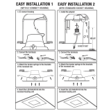
• Prepare fixture for recessed installation.(FIG.1)
• Remove lens by twisting counter clockwise. (FIG.2)
• Connect supply wires to wires on fixture with wire
nuts or push wires into Quick Connector.Connect
white to white , black to black,and copper wire to
copper wire as grounding connection.(FIG.3)
• Arrange the wires into the back of the junction box.
• Align appropriate holes in the mounting fixture with
the holes in the junction box.Using 2 of the longer
screws (either #6 or #8 screws depending on the size
of t h e h oles i n your j u n c tio n b o x ) a t t a ch t h e
mounting fixture is flush with the ceiling. Do not
over-tighten screws or fixture will not be tight to
ceiling. (FIG.4)
• Complete the installation by turn lens clockwise to
lock. (FIG.5)
Model No.
Voltage
Current
Wattage
D236
120V
012A
15

WARNING - RISK OF ELECTRIC SHOCK.
DISCONNECT MAIN POWER AT FUSE OR CIRCUIT
BREAKER BEFORE INSTALLING OR SERVICING
THE FIXTURE.
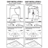
ASSEMBLY AND INSTALLATION
INCANDESCENT HOUSINGS
•Unscrew the WING NUT inside the CAN to detach the SOCKET
BRACKET from the CAN. Disengage the SOCKET from the SOCKET
BRACKET. (FIG. 2)
•Thread the SOCKET ADAPTER into the SOCKET. (FIG. 3)
•Place spring on mounting bracket and complete the installation by
twisting the lens on the light. (FIG. 4)
•If using TORSION SPRINGS, squeeze both TORSION SPRING arms
together and insert into the TORSION SPRING SLOTS (orplace spring
on mounting bracket RECEIVER BRACKETS) of the CAN. (FIG. 5)
•Tuck all wires into the CAN and carefully push the RETROFIT TRIM
into CAN. (NOTE: To provide enough room in shallow cans, carefully
position SOCKET ADAPTER and SOCKET adjacent to the long side of
the LED DRIVER prior to inserting the RETROFIT TRIM into the
CAN.) (FIG. 5)
LED HOUSINGS
•Plug the FEMALE CONNECTOR of the RETROFIT TRIM onto the
MALE CONNECTOR of the HALO HOUSING. (FIG. 5)
•If using TORSION SPRINGS, squeeze both TORSION SPRING arms
together and insert into the TORSION SPRING SLOTS (or RECEIVER
BRACKETS) of the CAN. (FIG. 5)
•Tuck all wires into the CAN and carefully push the RETROFIT TRIM
into CAN. (NOTE: To provide enough room in shallow cans, carefully
position SOCKET ADAPTER and SOCKET adjacent to the long side of
the LED DRIVER prior to inserting the RETROFIT TRIM into the CAN.)
(FIG. 5)
LED 6” DOWN LIGHT INSTALLATION INSTRUCTIONS
RETROFIT
DIMMING
Dimming performance may depend on the dimmer, the dimmer
range adjustment setting (for dimmers with brightness range
adjustments), the wiring method, and/or the number of LED
modules installed onto the dimmer circuit.
For dimmer selection, Dimming control manufacturers revise their
product often; for the latest list of compatible dimmers please visit
our website.
For best results, it is recommended to install a minimum of four LED
modules onto one dimmer.
Before turning on the LED lights, set dimmer position at maximum
before adjusting to a lower light level.
Please follow the dimming control manufacturer’s instructions for
the installation of all dimming controls.
Brand
Lutron
Leviton
Model
DVCL-153P-WH
6683
MACL-153M-WH
6672
S-600PR-WH
6631
SPSLV-600-WH
6633-P
DVLV-603P-IV
1A23O5
MALV-600-IV
0B33K1
MALV-600
DVW-603PGH-WH
4X603
CTCL-153P
SLV-600P-WH
DVW-603P6H-WH
CT-603PG
NT-1000
S-603P
DV-600P
RA-6D
Following is a list of recommended dimmers:
/


