5
BEFORE EACH OPERATION
Your safety is your responsibility. A little time spent in preparation will
significantly reduce your risk of injury.
Read and understand this manual. Know what the controls do and
how to operate them.
Familiarize yourself with the snow blower and its operation before you
begin using it. Know how to quickly shut off the snow blower in case of
an emergency.
Check Your Snow Blower
For your safety, and to maximize the service life of your snow blower,
it is very important to take a few moments before you operate the
snow blower to check its condition. Be sure to take care of any
problem you find, or have your servicing dealer correct it, before you
operate the snow blower.
• Make sure the snow blower is on a level surface and the engine
switch is in the OFF position.
• Look around and underneath the snow blower for signs of oil or
gasoline leaks.
• Check the auger housing and the discharge chute for accumulation
of packed snow or ice. Clean the auger housing and discharge
chute before starting the snow blower.
• Look for signs of damage.
• Check each control for proper operation.
• Check the auger and blower for loose or broken bolts. If broken,
replace them with new ones.
• Check the skid shoes and scraper for wear. Replace them if
necessary (see page 17).
• Check that all nuts, bolts, and screws are tightened.
• Check the oil level.
• Check the fuel level. Starting with a full tank will help to eliminate or
reduce operating interruptions for refueling.
Check Your Work Area
For your safety and the safety of others, always inspect the area
before operating the snow blower.
Anything that can be picked up by the auger and thrown is a potential
hazard to you and others. Thoroughly inspect the area where the
equipment is to be used and remove all doormats, newspapers, sleds,
boards, wires, stones, nails and debris from the work area.
People and animals near the work area can move into your snow
blower’s path or into a position where they could be struck by thrown
objects. Clear the area of people, especially children, and pets. Their
safety is your responsibility.
Check the condition of the snow. Adjust your snow blower ground
speed (not engine speed) and snow blowing swath accordingly.
Check the skid shoes for proper adjustment. Adjust the skid shoes to
obtain the proper auger ground clearance for the surface on which
you are operating (see page 17).
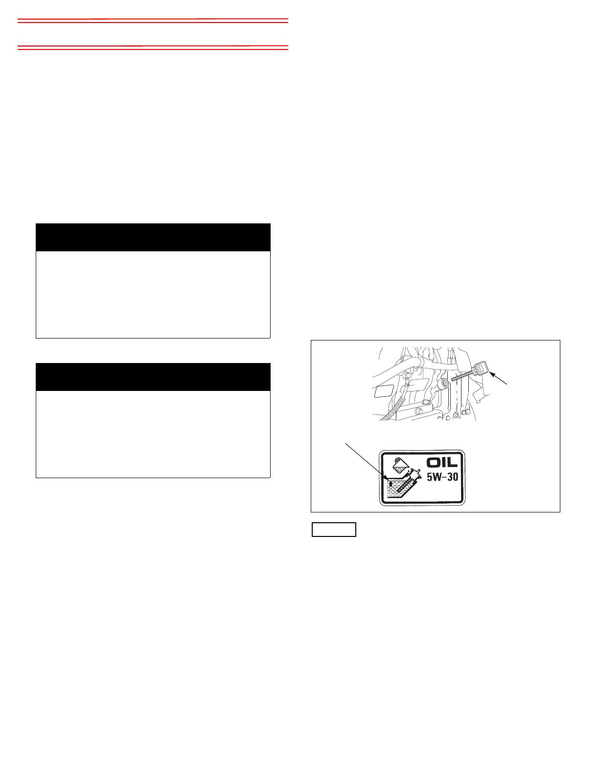
Check the Engine Oil Level
Check the engine oil level with the engine stopped and in a level
position.
1. Remove the oil filler cap.
2. Check the oil level. Do not thread the dipstick in when checking the
oil level. If it is below the upper limit mark on the dipstick, fill with
the recommended oil (see page 16) to the upper limit mark on the
dipstick. Do not overfill.
3. Reinstall the oil filler cap securely.
Running the engine with a low oil level can cause engine damage.
This type of damage is not covered by the Distributor’s Limited
Warranty.
Add Fuel
The snow blower engine is certified to operate on unleaded gasoline
with a pump octane rating of 86 or higher.
You may use regular unleaded gasoline containing no more than 10%
ethanol (E10) or 5% methanol by volume. In addition, methanol must
contain cosolvents and corrosion inhibitors.
Use of fuels with content of ethanol or methanol greater than stated
above may cause starting and/or performance problems. It may also
damage metal, rubber, and plastic parts of the fuel system.
Engine damage or performance problems that result from using a fuel
with percentages of ethanol or methanol greater than stated above
are not covered under the Distributor’s Limited Warranty.
WARNING
Exhaust contains poisonous carbon monoxide gas that
can build up to dangerous levels in closed areas.
Breathing carbon monoxide can cause
unconsciousness or death.
Never run the engine in a closed, or even partly closed
area where people may be present.
WARNING
Improperly maintaining this snow blower, or failing to
correct a problem before operation, could cause a
significant malfunction.
Some malfunctions can seriously hurt or kill you.
Always perform a pre-operation inspection before each
operation, and correct any problem.
OIL FILLER
CAP
UPPER LIMIT


