INSTALLATION INSTRUCTIONS
Read installation instructions rst before installing. Check parts to ensure that no damage has occurred during transit and that no
parts are missing. Also check the diameter of the pipe and the size marked on the coupling to ensure you have the proper size.
Document # 20-9-0035 11/22/2016
21919 20th Avenue SE • Suite 100 • Bothell, WA 98021 • Phone (425) 951-6200 • 1-800-426-9341 • Fax (425) 951-6201
7
9
8
6
FCG Flange Coupling Adapter
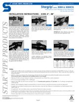
Step 8 • Slide the FCG Gland into position against the
gasket, and insert T-bolts.
When stainless steel fasteners are requested, Romac
provides all-thread-rod and two nuts. The underside of the
lug on the FCG body is designed to capture hex nuts as
well as "T" head bolts.
Step 1 • Check the FCG parts to insure that no damage
has occurred during transit and that no parts are missing.
Step 2 • Clean pipe end for a distance of 2" greater than
length of the FCG.
Step 3 • Place FCG gland on pipe end.
Step 4 • Lubricate the gasket and pipe surface with soapy
water or other suitable gasket lubricant.
Step 5 • Place gasket over pipe with beveled edge
toward the end of the pipe.
Step 6 • Slide the FCG on to the pipe. Position the pipe
and anged coupling against the mating ange. Assemble
the ange joint using ange bolts
(not provided).
Step 7 • The pipe should be centered such that the space
between the OD of the pipe and the ID of the FCG is even all
around the pipe. Slide the FCG gasket into position with the
beveled edge engaging the beveled end of the FCG body.
Step 10 • Pressure test for leaks before backlling.
Note:
90 ft-lbs. torque = 12" wrench w/90 lbs. force
For best results, wait 10 minutes and
retighten bolts to proper torque.
Recommended Torque:
3" FCG - 45-65 ft-lbs.
4 - 12" FCG - 75 - 90 ft-lbs.
Step 9 • Tighten T-bolts evenly, alternating to diametrically
opposite position at approximately 20 ft-lbs increments to the
recommended torque for your size FCG.


