13
36
BA
pression de gaz, dans ce cas le réglage de la amme la plus réduite doit se faire à la
basse pression dans l’installation de sorte que le brûleur ne s’éteigne pas pendant
l’utilisation normale.
- après avoir réglé les robinets, remonter les manettes et éteindre la amme.
Fig 03
2)
2
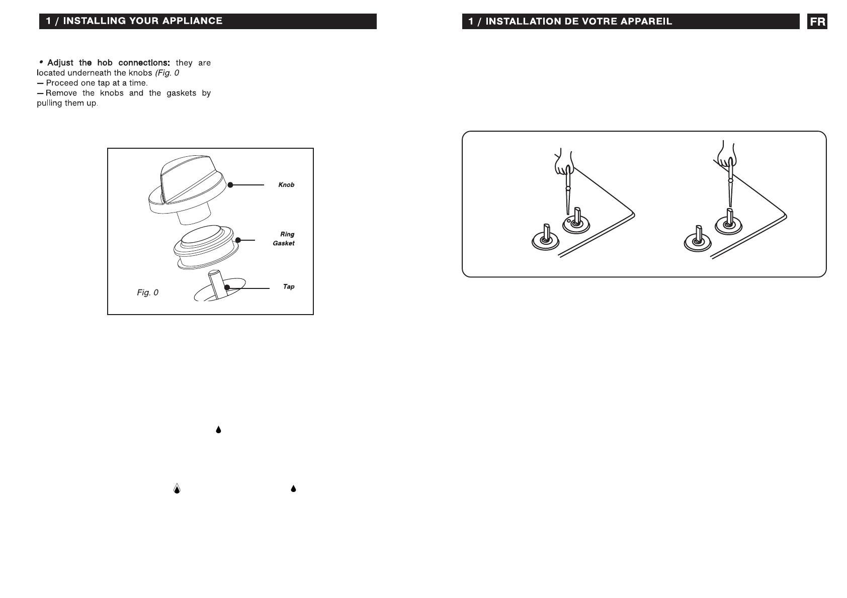
ADJUSTING THE TAPS
The adjustment of a gas tap consists in setting the burner flame in the simmering posi-
tion. To adjust the taps remove all the knobs and control panel.
Then:
- open the gas flow with a knob and light the adjusted burner,
- set the knob in the simmering position
. and then, without changing that position,
remove it from the tap's mandrel
- put a screwdriver in opening 'A" or mandrel opening "B" (depending on the type of the
tap - fig. 03) and turn it, observing the flame, to achieve such a size of the flame that
will prevent it from being extinguished in a slight draught or during the operation of
quick switching from the full
to the simmering position . of the flame and back;
the adjustment is correct when the core of the flame is cone-shaped in green and blue
colour and is ca. 2 - 4mm tall,
- if there are perceptible changes of gas pressure in the gas supply system,


