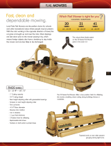
Agria 5556 Owner's manual

Type
Owner's manual

This manual is also suitable for

The Agria 5556 is a versatile and capable garden tiller, perfect for a variety of gardening tasks. With its powerful engine and sturdy construction, it can easily handle tough soil conditions and prepare your garden beds for planting. The adjustable tilling width allows you to customize the machine to your specific needs, and the depth control ensures that you can till to the desired depth. The Agria 5556 also features a reverse gear for easy maneuvering, and transport wheels for added convenience.

The Agria 5556 is a versatile and capable garden tiller, perfect for a variety of gardening tasks. With its powerful engine and sturdy construction, it can easily handle tough soil conditions and prepare your garden beds for planting. The adjustable tilling width allows you to customize the machine to your specific needs, and the depth control ensures that you can till to the desired depth. The Agria 5556 also features a reverse gear for easy maneuvering, and transport wheels for added convenience.

Operating Manual
SAFETY Mower SME3
Type 085, 105, 125, 145
for single-axle tractor
Maschinenfabrik
Bermatingen GmbH & Co. KG
Kesselbachstrasse 2
88697 Bermatingen
Germany
Phone
+49 (0) 75 44 / 95 06 - 0
Fax +49 (0) 75 44 / 95 06 - 20
Fax +49 (0) 75 44 /
9506  677
Declaration of conformity
for the device we have manufactured, the
SAFETY Mulcher
Type: Type
SME-3 085, 105, 125, 145,
Type: SME-H 085, 105, 125, 145
ID no.: Standard implement single-axle tractor 268 00 000
Hydraulic implement single-axle tractor 267 00 000
We confirm the compliance with the requirements of the Machinery Directive
2006/42/EC including its modifications and supplements published up to the present.
Corresponding technical documentation can be made available. The following standards
and directives were taken into account in the design and manufacture:
DIN EN ISO 12100:2011 Safety of machinery
(general, including risk assessment)
DIN EN ISO 13857-2008 Safety of machinery (hazard zones being reached
by upper and lower limbs)
DIN EN ISO 12100 + 14121 Safety of machinery – risk assessment
DIN EN 13 524 + A1 Machines for road maintenance service –
Safety requirements
EN 12733 Agricultural and forestry machinery,
pedestrian controlled motor mowers, safety
Authorised person for documentation: Wolfgang Websky.
For address, refer to manufacturer.
Maschinenfabrik
Bermatingen GmbH & Co. KG
Company management
Ulrich Gotterbarm
Bermatingen, May 2019
TABLE OF CONTENTS
Table of contents
Page
Information
Warning explanations
4
5
1
Safety requirements
6
1.1
General safety requirements
6
1.2
Hydraulic system safety requirements
6
1.3
Transport
6
1.4
Operation
7
1.5
Maintenance, care, repair
7
2
Attachment on the single-axle tractor
8
2.1
Attachment
8
2.2
Attachment with quick coupling
9
2.3
Attachment adapter
10
2.4
Attachment hydraulic drive
11
3
Adjustment tasks
12
3.1
Adjusting the cutting height on the attached single-axle tractor
12
3.2
V-belts
13
3.2.1
Checking the V-belt tension
13
3.2.2
Retensioning the V-belts
13
3.2.3
Replacing the V-belts
13
4
Rotational speeds rotor shafts
14
5
Working with the mulcher
15
5.1
Check before work
15
5.2
Mulching
15
5.3
Drive speed and cutting speed
15
6
Care and maintenance
16
6.1
Care of the mulcher
16
6.2
Protective cover
17
6.3
Lubricating the mulcher
18
6.4
Checking the blades
19
6.6
The gear oil
20
6.6
Use of spare parts
20
7
Technical data
21
ANGABEN
Attention
Note
Information concerning the mulchers
Address of manufacturer
Maschinenfabrik Bermatingen GmbH & Co. KG
Kesselbachstr. 2
88697 Bermatingen, Germany
Phone +49 (0) 75 44 / 95 06 0
Fax +49 (0) 75 44 / 52 07
Rating plate of your implement
Serial number (ser.no.) is located on the rating plate on your mulcher.
Please enter this serial number here:
Without this serial number, claims under guarantee and queries cannot be processed.
Symbols in these operating instructions
The following symbols are used in these operating instructions:
• Thissymbolispositionedbeforeactivitiestobecarriedout
Indication of danger to humans
Failure to comply with this information can result in hazards to life and
limb for people.
Indication of material or personal injury
Positionedbeforetextwhichprovidesadditionalinformation.
4
Operating Manual – SAFETY Mower and Flail Mower for Single-Axle Tractor
WARNINGS
Warnings for humus product line
Explanation of the pictograms
Danger due to rotating
machine parts.
Maintain a safe distance
when the motor is running.
Prior to maintenance and
repair tasks switch off the
motorandremovekey.
Read and comply with
the operating manual.
Wear eye protection and
hearing protection.
Operating Manual – SAFETY Mower and Flail Mower for Single-Axle Tractor
5
SAFETY REQUIREMENTS
1. Safety requirements
Are you among that group of people who do not read operating manuals?
For your own safety and for the safety of others you must read this manual before
starting up the implement.
In spite of high safety standards of the mulcher there is residual risk of hazards for people,
animals and objects is associated with its operation.
Due to the rotating blade roller you must pay particular attention to the
following dangers:
– Cutting unit damage due to foreign objects, such as bottles, metal parts, rocks, etc.
– Danger of injury due to rotating components
– Residual danger due to objects that are whirled up, such as rocks, etc.
Follow the instructions in this manual and you will enjoy working with your machine for
many years.
1.1 General safety requirements
1. Climbing on the mower is prohibited.
2. Only execute maintenance and inspection tasks under the lifted implement
that is additionally secured with support trestles.
3. Danger due to tools that do not come to an immediate standstill after they are
switched off.
4.Protectiveclothsandpendulumapsandtheirfasteningsmustbecheckedfor
damage.
In addition to the instructions below, the statutory safety and accident protection regulations
must also be complied with.
1.2 Machineswithhydraulicdrive–hydraulicsafetyrequirements
– Thehydraulicequipmentisconguredforamaximumpermissiblepressureof250bar.
At attachment to the towing vehicle, it must be ensured that this pressure is not exceeded
under any circumstances (adjustment of the vehicle-side pressure limiting valve).
Visually inspect the hydraulic lines prior to each start-up.
– Donot,underanycircumstances,workwiththeimplementifhosesandttings
are damaged.
– Hosesandttingsmustttogetherandshouldbefromthesamemanufacturer.
Hose lines must be checked for damage by an expert on a regular basis (at least once
ayear)(changmarks,cracks,cuts,bulges,etc.)andreplacedifnecessary.
Hydraulic hose lines must be completely replaced every 6 years at the latest.
Thedateofmanufactureisstampedonthelinetting.
Collect or bind escaping hydraulic oil and dispose of it as prescribed.
Comply with environmental regulations.
1.3 Transport safety requirements, front & rear attachment
• Attention:Onlytransportthemulcherinswitched-offstatus.
• OtherwisetheregulationsoftheHighwayTrafcAct(StVZO§53b)concerning
the recognition of attached devices; the owner is responsible in this regard.
6
Operating Manual – SAFETY Mower and Flail Mower for Single-Axle Tractor
SAFETY REQUIREMENTS
1.4 Operation
• Themulchermustonlybeusedformulchinggrass.
• Onlyexecutetheactivitiesdescribedinthisoperatingmanualonthemulcher.
• Neveroperatethemulcherwithdefectiveorlostprotectivedevices.
• Neverremoveprotectivedevice!
• Priortoeachstart-up,checkwhethercutterandfasteningscrewsareproperly
fastened and secured.
• Wearprotectivegoggleswhenmulching.
• Wearhearingprotectionwhenmulching.
• Usethechainattachedtoittosafeguardtheuniversaljointshaftprotectivepipe
from running along with the shaft (see operating manual of the universal joint shaft).
• Onlyswitchonthemulcherinloweredstatus.
• Priortomulching,foreignobjects(rocks,branches,bottles,etc.)mustberemoved
from the area to be mulched.
• Instructallpersonstoleavethedirecthazardarea.
• Onlytheoperator(tractoroperator)isallowedinthemulcher'shazardarea,
and the operator must be in the operating position/at the guide bar.
• Ifpersons,petsormotorvehiclesapproachthedirecthazardarea,mulchingmust
be interrupted.
• Withtheimplementattached,transportingotherpersonsonthepassengerseat
of the tractor is prohibited.
• Onlyliftoutthemulcherwhenthemowerisatacompletestandstill.
• Adifferentuseorusethatextendsbeyondthatspeciedabove,
aswellasunauthorizedmodicationareconsiderednon-intendeduse.
The manufacturer is not liable for damage resulting from non-intended use.
This risk is borne solely by the user.
1.5 Maintenance, care and repair
• Onlyperformthetasksdescribedinthisoperatingmanualformaintenanceand
care of the mulcher.
• Repairandoverhaultasksonthemulchermustonlybeperformedbythe
manufacturerorbytheauthorizeddealer(agriculturemachineworkshop).
• Onlyuseoriginalsparepartsfromthemanufacturer.
• Onlyperformmaintenanceandcaretasksinswitched-offstatusofthetowingvehicle,
and safeguard the towing vehicle from being switched on again.
• Neverpositionyourselfunderthenon-safeguardedmulcherforrepairorinspection.
Dimensionsofthehazard
area
Hazard area
40 m
7 m
Safety-Welle
Schlegel-Welle
Operating Manual – SAFETY Mower and Flail Mower for Single-Axle Tractor
7
ATTACHMENT ON THE TOWING VEHICLE
Priortoexecutingtheattachment,alwaysensurethattheproleoftheconnectionshaftand
theproleoftheconnectionpiecettogether.Thespecicationsoftheimplementcarrier
must also be taken into account.
Attention!
Fastenthedriveshaftfortransportofthemulchinghead(loosepart)!
Attachment:
• Alignmentofthemulchingheadtothesingle-axletractor
• Greasetheconnectionpiece
• Dismounttheprotectivecover
• Insertdriveshaft,checkthepositionaccordingtoimplementcarrierinformation!
• Joinsingle-axletractorandmulchingheadtogether.
• Inthisprocess,turnthedrivewiththebeltpulleysothatthegearingofthedrive
shaft engages, slide the devices together to the stop.
• Installthelockingscrew(bolt,snap-closure)ontheconnectionpiece.
• Checkimplementcarrierconnection(screws,snap-closure,bolt)lockingmechanism
• Greasetheconnectionpieceagain
Function test – test run:
Check rotor shaft speed and direction of rotation, see chapter "Rotor shaft speeds".
Thespeciedspeedofthebladeshaftsofthemachine(seestickeronthehousing)
must not be exceeded.
Brake test (at each new attachment, at least 2x a year):
• Brakeisinstalledinthegearbox
• Setthemax.speed
• Pullmotorclutchandswitchoffdrive
Thereafter the blade shaft must come to a standstill in approx. 7 seconds
The mulcher is now ready for operation
Generalcheckafterrststart-up
After approx. 2 hours of machine operation:
• CheckV-belts
• Checktrackroller
• Checkbladeshaft;rmseatofthebladeisstrictlyrequired!
• Re-greasealllubricatingpoints!
Connection adapter
for the single-axle
tractor
Attention
Note
2
Attachment on the single-axle tractor
2.1 Attachment
8
Operating Manual – SAFETY Mower and Flail Mower for Single-Axle Tractor
2.2 Attachment with quick coupling
Priortoexecutingtheattachment,alwaysensurethattheproleoftheconnectionshaft
andtheproleoftheconnectionpiecettogether.
Attention!
Fastenthedriveshaftfortransportofthemulchinghead(loosepart)!
Attachment:
• Alignmentofthemulchingheadtothesingle-axletractor
• Greasetheconnectionpiece
• Dismounttheprotectivecover
• Insertdriveshaft,checkthepositionaccordingtoimplementcarrierinformation!
• Joinsingle-axletractorandmulchingheadtogether.
• Inthisprocess,turnthedrivewiththebeltpulleysothatthegearingofthedriveshaft
engages, slide the devices together to the stop.
• Installthelockingscrew(bolt,snap-closure)ontheconnectionpiece.
• Checkimplementcarrierconnection(screws,snap-closure,bolt)lockingmechanism
• Greasetheconnectionpieceagain.
Function test – test run:
Check rotor shaft speed and direction of rotation, see chapter "Rotor shaft speeds".
Thespeciedspeedofthebladeshaftsofthemachine(seestickeronthehousing)
must not be exceeded.
Brake test (at each new attachment, at least 2x a year):
• Brakeisinstalledinthegearbox
• Setthemax.speed
• Pullmotorclutchandswitchoffdrive
Thereafter the blade shaft must come to a standstill in approx. 7 seconds
The mulcher is now ready for operation
Generalcheckafterrststart-up
After approx. 2 hours of machine operation:
• CheckV-belts
• Checktrackroller
• Checkbladeshaft;rmseatofthebladeisstrictlyrequired!
• Re-greasealllubricatingpoints!
ATTACHMENT ON THE TOWING VEHICLE
The locking screw can
be used for a rigid or
pivoting mulching head
– for this it must be
screwed in either on
the left or right.
·
Hook-in quick coupling
·
Hook-in and tighten
the locking screw
·
Note
Operating Manual – SAFETY Mower and Flail Mower for Single-Axle Tractor
9
2.3 Attachment adapter
Thesafetymulchersforsingle-axletractorsareattachedwithtype-specicadapters.
Drive speed variants of single-axle tractors 840 rpm, 900 rpm, 1000 rpm
ATTACHMENT ON THE TOWING VEHICLE
Aebi
Köppl
Attention
Irus
Rapid
Agria
Reform
Operating Manual – SAFETY Mower and Flail Mower for Single-Axle Tractor
ATTACHMENT ON THE TOWING VEHICLE
2.4 Attachmentwithhydraulicdrive
For all tasks on the hydraulic system of this implement, the hydraulic safety
requirements on page 6 point 1.2 must be strictly complied with.
The attachment is executed by an authorised specialist. This machine type is not driven
with a universal joint shaft, but rather it is driven hydraulically.
Thecongurationofthemulcherandtheconnectionconditionwasalreadyspeciedwhen
the machine was purchased.
Atrstattachmentandrststart-up
• aspeedcheckonthecuttingrollerand
• capacitycheckofthehydraulicsystem
must always be executed by the same specialised workshop.
Neverexceedthehighestpermissiblebladeshaftspeed.
Thehighestpermissiblebladeshaftspeedforyourimplementisspeciedonthe
sticker next to the rating plate.
Attention
Operating Manual – SAFETY Mower and Flail Mower for Single-Axle Tractor
ADJUSTMENTTASKS
Note
3.
Adjustment tasks
3.1 Adjusting the cutting height on the attached single-axle tractor
Ontheimplementcarrierpulltheparkingbrakeandswitchoffthedrivemotor!
Basic setting A and B results in a cutting height of approx. 50 mm.
Basic setting of the cutting height:
• Positionmulchinghousingwithtoplink3 parallel to the level surface A .
• IfthetrackrollerisnotinB,thenunscrewthreadedttings1 , re-insert track roller
in Bandtightenthreadedtting.
Fast adjustment of the cutting height:
• Unscrew2 screws and adjust the cutting height by turning the top link 3 .
Top link:
Cutting height
adjustment
element.
Cutting height
adjustment with
top link:
Unscrew screws
Cutting height basic setting
3
2
1
B
A
The fast adjustment of the cutting
height is easy to executed with the
provided special spanner 4 .
4
Note
Recommended cutting height adjustment for the following conditions:
– Difcultterrain: Setthecuttingheighthigher!
– Lowenginepower: Setthecuttingheighthigher!
– Reducefuelconsumption: Setthecuttingheighthigher!
– Cleancut: Setthecuttingheightlower!
– Improvethecuttingquality Setthecuttingheightlower!
Operating Manual – SAFETY Mower and Flail Mower for Single-Axle Tractor
3.2 V-belts
All tasks on the V-belts must only be performed when the mulcher is switched
off and has been safeguarded from being switched on again.
Atrstuseofthemulcher,checktheV-belttensionafter1/2hourofoperation.
Check the V-belt tension after overload or at each lubrication interval.
3.2.1 Check the V-belt tension
1. Open the inspection cover A
2. Push on the belt (Fig. 3).
3. At a pressure of 50 N it should be possible to press the belt in approx. 0.5 cm.
4. Close the inspection cover.
3.2.2 Check and retension the V-belts
1. Dismount the protective cover. (Fig. 2)
2.VisualinspectionoftheV-beltdriveforcontamination,looseparts,
and wear of the parts
3. Retension: Unscrew fastening screws 1 and 2 (8 screws in total).
4. Slide the gearbox parallel with the aid of tension screw 3 until the correct belt
tension is achieved (50 N, belt can be pushed in 0.5 cm).
5. Fix fastening screws in place and mount the protective cover.
3.2.3 Replacing the V-belts
1. Dismount the protective cover. (Fig. 1)
2.VisualinspectionoftheV-beltdriveforcontamination,looseparts,
and wear of the parts
3. Replacing: Loosen fastening screws 1 and 2 , as well as tension screw 3 .
4. Slide gearbox to the stop; ensure the least possible centre distance of the
belt pulleys.
5. Replace V-belts.
6. To tension the new belts execute the steps in the reverse sequence.
7. Check V-belt tension after 1/2 hour of operation.
Attention:
1
2
3
Fig. 2
Fig. 3
ADJUSTMENTTASKS
Fig. 1
A
0,5 cm
Operating Manual – SAFETY Mower and Flail Mower for Single-Axle Tractor
4. Rotational speeds – rotor shafts
Attention:Rotorshaftspeedmustbecheckedatrststart-upor
when the single-axle tractor is changed.
Max. permissible rotation on the rotor shafts:
ADJUSTMENTTASKS
ATTENTION: Themaximumrotationalspeedforyourimplementisspecied
on a yellow sticker next to the rating plate!
ATTENTION: Forsafetyreasonsthemaximumrotationalspeedsmustnever
be exceeded!
Flail shaft works effectively starting at a rotational speed of 2700 rpm.
Safety shaft works effectively starting at a rotational speed of 4000 rpm.
Drive-speedvariantsonthesingle-axletractor:
840 rpm, 900 rpm, 1000 rpm
Hydraulicdrive:
Rotational speed is set according to the power of the single-axle tractor.
Check the rotational speed and direction of rotation:
Remove belt guard and check the rotational speed on the centring element
of the cutter shaft with a rotational speed measuring device.
(Safety shaft = 4000 – 4950 rpm, Rotor shaft = 2700 – 3100 rpm)
Safety shaft:
4950 rpm
Rotorshaft–ails:
3100 rpm
Rotorshaft–ne-cutblade:
3100 rpm
Operating Manual – SAFETY Mower and Flail Mower for Single-Axle Tractor
5. Working with the mulcher
5.1 Check before work
Prior to each start-up of the mulcher you must execute the following
preliminary tasks:
• Checksonthemulcher:
Check for completeness of the protective devices
Check for completeness of the fastening bolts and locking pins
of the implement suspension
Check the fastening of the blades
– Faultlessconditionoftheblades–notnotched,damagedorworn!
Ensure adequate lubrication
Check the tension of the V-belts
• Removesolidobjects(e.g.rocks,wires,piecesofwood,molehills,etc.)
from the area to be mulched.
• Instructpersonstoleavethedirecthazardarea.
Attention: Onlystartupthemulcherafterallsafetyrequirementshavebeen
fullled(seesection1.).
5.2 Mulching
After the mulcher is attached on the tractor, all adjustment tasks have been
executed, the mulcher has been checked (section 5.1) and the safety precautions
have been taken, you can now mulch.
To mulch, proceed as follows:
• Lowerthemulcher.
• Switchonthedriveshaftandincreasethespeedtotheratedspeed.
• Themulcherisreadyforoperation.
5.3 Drivespeedandcuttingspeed
The drive speed is based on the density, the height and the condition of the mulch
material.Thenenessofthemuchmaterialdecreaseswithincreasingdrive
speed. To achieve optimal mulching performance, we recommend the highest
permissible PTO shaft speed / cutting roller speed.
Blades in good condition ensure a higher work rate and lower fuel consumption,
ascomparedtowornordamagedblades!
Flail shaft works effectively starting at a rotational speed of 2700 rpm.
Safety shaft works effectively starting at a rotational speed of 4000 rpm.
CARE AND MAINTENANCE
Operating Manual – SAFETY Mower and Flail Mower for Single-Axle Tractor
6. Care and maintenance
• Onlyperformthetasksdescribedinthisoperatingmanualforcareand
maintenance of the mulcher.
• Repairandoverhaultasksonthemulchermustonlybeperformedbythe
manufacturerorbytheauthorizeddealer(agriculturemachineworkshop).
• Onlyuseoriginalsparepartsfromthemanufacturer,otherwisetheguaranteeand
liability are invalidated.
• Onlyperformmaintenanceandcaretasksinswitched-offstatusofthemulcher,
and safeguard the mulcher from being switched on again (Unplug the spark plug
connector).
• Neverpositionyourselfunderthenon-safeguardedmulcherforrepairorinspection.
6.1 Care of the mulcher
Care is cheaper than repair. Consequently you should execute the following tasks
on a regular basis:
• Aftereachworkdeployment
• Every10operatinghours
• Every1000operatinghours
Clean the mulcher
Attention: When using a high-pressure cleaner
do not aim the water jet at the bearing positions.
Inspect the gearbox for indications of oil loss.
Lubricate the mulcher
Replace gear oil
CARE AND MAINTENANCE
Note: After each use and after each cleaning the mulcher must be
thoroughly lubricated.
Operating Manual – SAFETY Mower and Flail Mower for Single-Axle Tractor
6.2 Protective Cover
The mowing device has a protective flap that can only be opened for
maintenance, cleaning or changing the blades!
The protective cover can be adjusted by turning the turnbuckle manually.
Release screw and nut pos. (1) and remove.
Loosen the nut Pos (2).
Turn the turnbuckle nut pos. (3) to the desired position of the protective cover.
To secure the position, tighten the nut Pos (2) again.
To close the cover, proceed in reverse order.
Protective-cover
2
3
1
CARE AND MAINTENANCE
Operating Manual – SAFETY Mower and Flail Mower for Single-Axle Tractor
Type 085, 105, 125, 145
Thebearingsofthesafetymulchermustbelubricatedasspeciedinthetable.
Lubricating points are marked in red.
Item Lubricating point Lubricant Number of Operating
lubricating points hours
1 Blade shaft left Lubricating grease K 2 1 lubricating nipple 15 h
K-30 (DIN 51502)
2 Blade shaft right Lubricating grease K 2 1 lubricating nipple 15 h
K-30
3 Track roller left Lubricating grease K 2 1 lubricating nipple 25 h
K-30
4 Track roller right Lubricating grease K 2 1 lubricating nipple 25 h
K-30
5 Rotary connection Lubricating grease K 2 2 lubricating nipple 15 h
(adapter) K-30
CARE AND MAINTENANCE
6.2 Lubricating the mulcher
Attention: Only lubricate the mulcher when the implement is switched off.
Thebearingsofthemulchershouldbelubricatedasspeciedinthetable.
All lubricating points are marked by stickers/red dot.
The lubricating points of the main bearings are covered by plastic caps.
Operating Manual – SAFETY Mower and Flail Mower for Single-Axle Tractor
CARE AND MAINTENANCE
6.3 Checking the blades
Check the blade segments and their fastening
Heavily worn blades or blades with broken off teeth do not mow cleanly and
consequently must be replaced. In addition they cause imbalance and over time this
can damage the implement. The entire blade set or sections, for each circumference
of the blade shaft must be replaced.
NOTE: Prior to inspection, maintenance and repair tasks the mower head
must be set down safely, in such a manner that it cannot tip.
Thenthetaskscitedbelowcanbeexecuted,e.g.aboveaworkpit
or with the aid of a trolley.
Attention: Only the manufacturer or an authorised specialist is allowed to
replace the blades of the mower.
DANGER: Neverperformweldingtasksonthebladesortheirfasteningpoints.
These points are made of a hardened steel. After heat exposure
these points can break easily and cause an accident.
Checking the fastening
DANGER: The fastening of the blades must only be checked after the blade
shaft(wormshaft)andthevehiclemotorhavecometoacomplete
tandstill. Pay attention to the stopping time of the blade shaft.
The fastening and faultless condition of the blade segments must
be checked before each use of the safety mulcher and after hitting a solid
obstruction (see 6.3 Checking the blades).
Check the following components of the blade fastening correct seat:
Fastening parts: 3 screws (strength class 10.9) with self-locking nuts
(DIN 980 strength class 10.9) per segment.
Tightening torque: 70 ± 2 Nm – M10 screws
35 ± 2 Nm – M8 screws
ATTENTION: Danger of injury
Before each task on the blade shaft the motor must be switched
off and you must wait until the blade shaft comes to a standstill.
(Payattentiontothestoppingtimeoftheblad shaft!)
Operating Manual – SAFETY Mower and Flail Mower for Single-Axle Tractor
CARE AND MAINTENANCE
6.4 The gear oil
Because the gearbox is basically maintenance-free,
topping up gear oil is dispensed with.
If there are leaks the gearbox must be repaired immediately
by a specialised workshop.
The gear oil must be replaced every 1000 operating hours. Go to a specialised
workshop for this.
Note: Heating of the gearbox to 80°C during operation is normal.
Attention: Only the manufacturer or an authorised workshop is allowed
to repair the gearbox.
6.5 Use of spare parts
Always use only original "humus" spare parts. If other parts are used the product
liabilityinaccordancewithCE-conformityisinvalidated!
When ordering spare parts, always specify the precise type, model year,
and the machine number of the mulcher.
Maschinenfabrik Bermatingen GmbH & Co. KG
+49(0)7544/9506-0,Fax+49(0)7544/9506  677
Spare part orders +49 (0) 7544-9506-41 or 42
Fig.: Gearbox
Operating Manual – SAFETY Mower and Flail Mower for Single-Axle Tractor
  • Page 1 1
  • Page 2 2
  • Page 3 3
  • Page 4 4
  • Page 5 5
  • Page 6 6
  • Page 7 7
  • Page 8 8
  • Page 9 9
  • Page 10 10
  • Page 11 11
  • Page 12 12
  • Page 13 13
  • Page 14 14
  • Page 15 15
  • Page 16 16
  • Page 17 17
  • Page 18 18
  • Page 19 19
  • Page 20 20
  • Page 21 21
  • Page 22 22
  • Page 23 23
  • Page 24 24
  • Page 25 25

Agria 5556 Owner's manual

Type
Owner's manual
This manual is also suitable for

The Agria 5556 is a versatile and capable garden tiller, perfect for a variety of gardening tasks. With its powerful engine and sturdy construction, it can easily handle tough soil conditions and prepare your garden beds for planting. The adjustable tilling width allows you to customize the machine to your specific needs, and the depth control ensures that you can till to the desired depth. The Agria 5556 also features a reverse gear for easy maneuvering, and transport wheels for added convenience.

Ask a question and I''ll find the answer in the document

Finding information in a document is now easier with AI