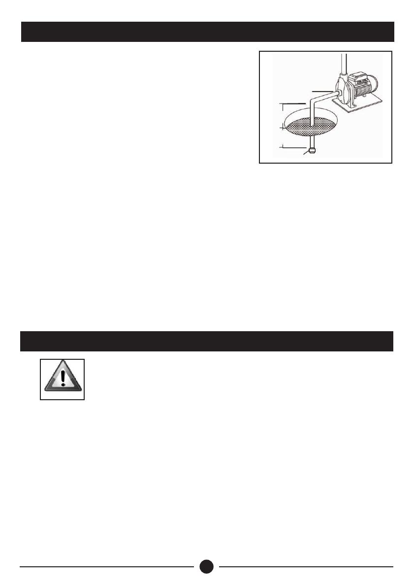
DAYLIFF DDP50A User manual

Type
User manual

DAYLIFF DDP50A is a high-performance domestic water pump suitable for a wide range of applications, including water supply for homes, gardens, and small-scale agricultural irrigation. Featuring a durable cast iron body and a high-capacity motor with stainless steel housing inserts, it ensures longevity and reliable operation. With its intelligent electronic microprocessor, the DDP50A automatically starts and stops the pump based on water demand, providing consistent pressure and saving energy.

DAYLIFF DDP50A is a high-performance domestic water pump suitable for a wide range of applications, including water supply for homes, gardens, and small-scale agricultural irrigation. Featuring a durable cast iron body and a high-capacity motor with stainless steel housing inserts, it ensures longevity and reliable operation. With its intelligent electronic microprocessor, the DDP50A automatically starts and stops the pump based on water demand, providing consistent pressure and saving energy.

DD
Domestic Pumps
Installation &
Operating Manual
DDP DDC
DDJ
DDS
DDT
DDG
DDP50A
PUMP SPECIFICATIONS
1.
1
2.
INSTALLATION 4
ELECTRICAL CONNECTIONS
3.
4
PRIMING
4.
5
MAINTENANCE
5.
5
INDEX
© Davis & Shirtliff Ltd 2022
Contents herein are not warranted
TROUBLE SHOOTING
6.
6
WARRANTY
7.
7
1
1. PUMP SPECIFICATIONS
60
DDP
3
FLOW RATE (m /hr)
10
20
30
40
50
60
01 2 3 4 5
PUMP HEAD (m)
DDJ 750
DDJ 1100
DDJ
25
DDC
PUMP HEAD (m)
3
FLOW RATE (m /hr)
012 3 45678
5
10
15
20
25
30
40
35
45
DDC 158
DDC 170
Congratulations on selecting a Dayliff Domestic Pump. They are
manufactured to the highest standards and if installed and operated
correctly will give many years of efcient and trouble free service.
Careful reading of this Installation Manual is therefore important,
though should there be any queries they should be referred to the
equipment supplier.
FLOW RATE (m/hr)
3
PUMP HEAD (m)
10
20
30
40
0
0.5 11.5 22.5 3.5
3
50
DDP 60 DDP 65
DDP 60E
DDP50/DDP65A
FLOW RATE (m/hr)
PUMP HEAD (m)
DDP50A
DDP65A
DDP65A OPERATING RANGE
DDP50A OPERATING RANGE
0 0.5 1 1.5 2
5
10
15
20
25
30
35
40
2.5
2
DDG
3
FLOW RATE(m/hr)
0
20
25
40
10
15
30
35
0.5 11.5 2 2.5 3.53
DDG 1000
PUMP HEAD (m)
DDG 1000
5
PUMPS
The Dayliff DD pump range is specially designed for all small scale domestic and
commercial water supply uses. Model options are available as follows:
DDP: High specification peripheral pumps that features copper windings, a high
capacity motor and stainless steel housing inserts to ensure free impeller movement.
The pump body is manufactured from cast iron and the impeller from brass.
DDP60E is of lighter construction and does not feature stainless steel housing
inserts. DDP50A incorporates mechanical pressure control start and stop while
DDP65A incorporates an electronic microprocessor that starts and stops the pump
automatically,
DDC: Centrifugal non-self priming closed impeller pumps particularly suited for
water boosting and transfer applications. The pump body is cast iron and the
impeller stainless steel for DDC 158 and brass for DDC 170.
DDJ: Centrifugal jet type pumps that incorporate an integral ejector unit to provide
highly effective self priming performance. The pump body is made from cast iron,
the ejector from engineering plastic and impeller from brass.
02 4 86
15
10
5
25
20
40
35
30
10
DDS 750
3
FLOW RATE (m /hr)
PUMP HEAD (m)
DDS
DDT
3
FLOW RATE(m/hr)
PUMP HEAD (m)
0 1.0 1.5 2.0 2.5 3.0 3.5
5
10
55
40
35
30
25
20
15
0.5
50
45 DDT 10
Current
(A)
3
Pump Power Dimensions (mm) Weight
(kg)
kW L WDN1 DN2 H
Pump Data
Enclosure Class: IP44 Insulation Class: F Voltage:1x240V
DDJ750 0.75 5.2 1” 1” 435 191 200 17
DDP60 0.37 2.5 1” 1” 265 118 151 5.3
DDP65 0.75 5.2 305 136 181 10
DDS750 0.75 5.2 1” 315 213 232 14
1
1/”
4
1/”
DDJ1100 1.1 71
21” 515 209 218 32
DDG1000 0.8 2.5 1” 336 201 244 7
1”
DDC170 1.1 7345 230 293 21
1
1/”
2
DDC158 0.75 5.2 1” 1” 305 190 260 13.8
DDP60E 0.37 1.8 1” 1” 254 118 150 4.4
1
1/”
2
1/” 1/”
1
1/”
2
1/” 1
1/”
2
1/”
DDP50A 0.25 225 25 265 200 256 9
DDP65A 0.37 2.1 1” 1” 268 121 240 9
DDS: Centrifugal single impeller non-self priming pump. The pump body,
backplate and impeller are made from 304 stainless steel.
DDG: Single stage centrifugal impeller self priming design. Materials of
construction are stainless steel for the pump body, shaft and back plate with the
impeller made from polypropylene.
DDT: Single stage centrifugal impeller self priming design suitable for small scale
irrigation, water boosting and water transfer applications. Material of construction
are stainless shaft, UV-proof composite material for the pump body and all hydraulic
components in contact with water are made of engineering plastic.
MOTORS
Pumps are close-coupled to reliable TEFC electric motors designed for continuous
operation and are provided with a thermal cutout to protect against electrical
overload. They can be connected directly to the mains power supply through a 10A
fuse or MCB.
DDT 0.75 5.2 1” 388 194 198 10.4
1”
4
2. INSTALLATION
Foot Valve
UPWARD SLOPE
TO SUCTION
Max 5m
Min 50cm
Site in a dry, well ventilated and weather proof
location with an ambient temperature of no
0
more than 40 C.
ŸLocate on a solid flat surface ensuring the
shaft is in a horizontal position.
ŸEnsure that the diameter of the suction
pipe is at least the size of the pump suction
inlet. If the suction depth exceeds 4 meters
then a one size larger diameter pipe should
be used, though for maximum pump
performance suction height should be minimised.
ŸIf there is negative suction (i.e. the pump is above the suction water level) the
suction pipe must be slightly angled upwards towards the pump inlet to avoid
the formation of air locks. It must also be immersed in water by at least 0.5m to
avoid the formation of vortexes and a good quality foot valve must be fitted.
ŸEnsure that all suction pipe connections are completely airtight or else the
pump will not operate. The diameter of the delivery pipe must be chosen to suit
the flow rate and pressure required at the delivery point though must not be
smaller than the pump outlet size. It is also advisable to fit a non-return valve
and isolating valve on the delivery outlet. This measure is essential if the
delivery pressure exceeds 20 meters.
3. ELECTRICAL CONNECTIONS
WARNING
The installer is responsible for making electrical
connections to the mains supply in compliance with
relevant local regulations. Ensure that a professional
electrician carries out the electrical connections and that
the following guidelines are followed:-
All installations must be provided with an isolator to cut off mains power
supply and coarse current protection in the form of a fuse or MCB rated at 2-3
times the full load current as given on the pump plate.
Ensure that the power supply rating complies with the specification on the
pump rating plate.
Electrical connections must be made according to details in the pump
junction box cover and effective earthing must be provided according to local
regulations.
Single-phase motors are protected against overloads by a thermal
overload fitted in the motor windings.
5
4. PRIMING
FILL
WARNING
All non-self priming pumps must be primed
before operation. To do this completely fill
the pump housing with clean water through
the priming plug before switching it on.
When full replace the priming plug and start
the pump checking there is a steady flow at
the pump outlet. The pump should be
primed whenever it has not been used for a
long period of time or when air has entered
into the system.
Serious damage will occur if a pump is not properly
primed and runs without water.
Never carry out any work on the pump without
having rst disconnected from the mains supply.
5. MAINTENANCE
WARNING
Pumps do not require routine maintenance provided the following
precautions are taken:-
Check that the foot valve is clean and unrestricted at regular intervals.
If the pump is to remain unused for long periods of time it is advisable to
empty it completely, rinse it with clean water and store in a dry place.
If the shaft does not run freely, release it using a screwdriver by inserting it
in the special slot on the rear of the pump shaft. If this is not sufficient to
solve the problem remove the pump body by unscrewing the relevant
mounting bolts and clean it thoroughly to remove any encrustation.
6
6. TROUBLE SHOOTING
PROBLEM POSSIBLE CAUSE SOLUTION
Motor won’t
start
Check connections and power
supply
See section on maintenance
Flow rate
insufficient
Reduce suction height
Clean foot valve and, if necessary
whole Intake pipe
Disassemble pump and carefully
clean pump body and impeller
Tripped motor
overload
Check voltage and ventilation
Release impeller
(See section on maintenance)
Motor turns
without
pumping Move pump closer to water level
Check suction pipe is airtight
Make sure foot valve is immersed
by at least 50cm
Pump needs to be primed
Clean foot valve
Excessive suction height
No Power
Impeller stuck
Foot valve partially clogged
Impeller blocked
Suction height at limit
Overheated motor
Impeller stuck
Air in suction
Clogged foot valve
Delivery head exceeds pump capacity Reduce delivery head
Specify different pump
7. TERMS OF WARRANTY
i) General Liability
ii) Standard Warranty
7
In lieu of any warranty, condition or liability implied by law, the liability of
Dayliff (hereafter called the Distributor) in respect of any defect or failure
of equipment supplied is limited to making good by replacement or
repair (at the Distributor discretion) defects which under proper use
appear therein and arise solely from faulty design, materials or
workmanship within a specified period. This period commences
immediately after the equipment has been delivered to the
customer and at its termination all liability ceases. Also the warranty
period will be assessed on the basis of the date that the Distributor is
informed of the failure.
This warranty applies solely to equipment supplied and no claim for
consequential damages, however arising, will be entertained. Also
the warranty specifically excludes defects caused by fair wear and tear,
the effects of careless handling, lack of maintenance, faulty installation,
incompetence on the part of the equipment user, Acts of God or any
other cause beyond the Distributors reasonable control. Also, any repair
or attempt at repair carried out by any other party invalidates all
warranties.
General Terms
If equipment failure occurs in the normal course of service having been
competently installed and when operating within its specified duty limits
warranty will be provided as follows:-
Up to two years - The item will be replaced or repaired at no
charge.
Over two years, less than three years - The item will be replaced or
repaired at a cost to the customer of 50% of the Davis & Shirtliff
market price.
The warranty on equipment supplied or installed by others is conditional
upon the defective unit being promptly returned free to a Davis &
Shirtliff ofce and collected thereafter when repaired. No element of site
repair is included in the warranty and any site attendance costs will be
payable in full at standard chargeout rates.
Also proof of purchase including the purchase invoice must be provided for
a warranty claim to be considered
INS178G-11/22
  • Page 1 1
  • Page 2 2
  • Page 3 3
  • Page 4 4
  • Page 5 5
  • Page 6 6
  • Page 7 7
  • Page 8 8
  • Page 9 9
  • Page 10 10
  • Page 11 11
  • Page 12 12

DAYLIFF DDP50A User manual

Type
User manual

DAYLIFF DDP50A is a high-performance domestic water pump suitable for a wide range of applications, including water supply for homes, gardens, and small-scale agricultural irrigation. Featuring a durable cast iron body and a high-capacity motor with stainless steel housing inserts, it ensures longevity and reliable operation. With its intelligent electronic microprocessor, the DDP50A automatically starts and stops the pump based on water demand, providing consistent pressure and saving energy.

Ask a question and I''ll find the answer in the document

Finding information in a document is now easier with AI