Page is loading ...

6400 SYCAMORE CANYON BLVD.
RIVERSIDE, CALIFORNIA 92507
855-680-9595
WWW.DV8OFFROAD.COM
PRODUCT
INSTALLATION MANUAL
STEEL FRONT WINCH BUMPER
2019+ DODGE RAM 1500
FBDR1-05
TOOLS REQUIRED SKILL LEVEL TIME REQUIRED
- 8mm, 10mm, 13mm, 18mm, 21mm
Sockets
- Rachet
- T40 Torx Bit
- Trim Clip Tool
- Zipties (Optional)
- Rubber Mallet
Before you install this kit — Read and understand all
instructions, warnings, cautions, and notes contained in
this installation instruction guide. Consult your vehicle
owner’s manual for proper disconnection of electrical and
lifting of vehicle if required for installation of this product.
This install may require some technical skills and
knowledge of basic mechanical work. If you do not feel that
you are capable of performing this install please take this
product to a trained professional.
After reading this guide please contact us with any
questions or concerns before installing product.
Customer Service: 855-680-9595
DV8 Offroad is not responsible for any bodily injury or harm to you
or your vehicle as a result of an improper install.
Proper installation of this kit required knowledge of the factory
recommended procedures for removal and installation of original
equipment components. We recommend that the factory shop manual
and any special tools needed to service your vehicle be on hand during
the installation. Installation of this kit without proper knowledge of the
factory recommended procedures may affect the performance of these
components and the safety of the vehicle
• Always wear eye protection when operating power tools
Inspect all contents of this package to make sure product is not damaged
and all installation hardware has been included. If parts are missing from
kit, please be prepared to provide the following information
1. Name of purchase location
2. Bar Code on side of box
3. Date above bar code
4. Date inside box cover
- Novice/Intermediate
- 2 persons
- 3 Hours
Time to install this should only
take about three hours.
WARNINGS/CAUTIONS BEFORE STARTING INSTALLATION
855-680-9595
NEED HELP?
Little skill level required, however,
assistance is required for removal and
installation of bumpers.

INSTALLATION MANUAL
NEED HELP? 855-680-9595
STEP 1 | Unplug the fog light
connector by pressing the release tab and
pulling. Use a trim clip tool if necessary.
This is located behind the bumper, in
front of the driverside tire.
If you do not have an air dam, skip to step
4.
STEP 2 | Use an 8mm socket the
remove the bolts securing the inner
fender to the vehicle located in front of
the tires on both sides of the vehicle.
Begin by unpacking all items and inspecting
for missing pieces or damage. If you have any
concens, please contact the company the
product was purhcased from. Extra hardware
may be included with the product.
(2) M14x35 Hex
(18) M12x35
(4) M12x25
(44) M12 Flat Washers
(22) M12 Split Washers
(18) M12 Nuts
(2) M8x25
(2) M8 Flat Washer
(2) M8 Split Washer
(2) M8 Nuts
(4) M6x10 Allen
(4) M6 Nut
HARDWARE INCLUDED

INSTALLATION MANUAL
NEED HELP? 855-680-9595
STEP 3 | Use a 13mm socket to
remove the (4) bolts securing the air dam
and set it off to the side.
These are located in front and above the
A-arm, directly behind the air dam.
First picture shows where to air dam is
mounted with the bumper off the vehicle
for reference.
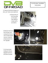
STEP 4 | Disconnect the main
bumper harness connector located
behind the inner fender on the driver side
of the vehicle. Pull the red locking clip
back and rotate the gray lock to release,
then pull.
A-Arm

INSTALLATION MANUAL
NEED HELP? 855-680-9595
STEP 5 | Use an 18mm socket to
remove the (6) nuts securing the bumper
to vehicle.
Note: Bumper will become loose when removing
these bolts and may fall. Assistance is
recommended to prevent injury or damage to
the product and vehicle.
STEP 6 | Use an 18mm and 21mm
socket to remove the (4) bolts securing
the tow hooks and set them off the side.
Note: It may be necessary to use a rubber
mallet to break the hook loose. Be careful when
removing this hardware, as the hook is very
heavy and may fall when removing hardware.

INSTALLATION MANUAL
NEED HELP? 855-680-9595
STEP 7 | Use an 8mm socket to
remove the bolts securing the inner
fenders to the bumper and set them off to
the side.
STEP 8 | Unclip connectors for the
fog lights by pressing the release tabs
and pulling.
These are located on the backside of both
fog lights.
Use a trim clip tool if necessary.
STEP 9 | Use a trim clip tool to
remove the clips securing the wiring
harness to the bumper brace.
Note: Wiring harness will not be removed
until after the bumper brace is removed.
(Step 9)

INSTALLATION MANUAL
NEED HELP? 855-680-9595
STEP 10 | Use a 10mm and 13mm
sockets with a T40 torx bit to remove the
bolts securing the bumper brace to the
bumper.

INSTALLATION MANUAL
NEED HELP? 855-680-9595
STEP 11 | Remove the metal bumper
from the trim piece while being careful to
avoid pulling on any wiring.
STEP 12 | Remove the sensors from
their bezels by gently spreading the tabs
that are securing it, and remove.
STEP 13 | Remove the sensor bezels
from the bumper by pressing the small
triangular tabs keeping the bezels in
place, while gently pushing “out” towards
the face of the bumper.
Note: Take notice the location/position of
the sensor bezels during removal, for easier
installation..

INSTALLATION MANUAL
NEED HELP? 855-680-9595
STEP 14 | Install the sensor bezels
on the DV8 bumper and wings in the
orientation/position they were removed.
STEP 15 | Install the (2) center
sensors into their bezels by gently
pressing them, until they “clip” into place
and are secure.
STEP 16 | Slide the outer sensors
through the cutouts at the lower section
of the bumper, to prepare for installation
of the bumper on the vehicle.

INSTALLATION MANUAL
NEED HELP? 855-680-9595
STEP 17 | If you are installing a
winch, do so at this time using the
hardware provided with the winch.
STEP 18 | If you are installing a
fairlead, do so at this time using the
hardware provided with the fairlead.
STEP 19 | Loosely install the new
frame brackets using the provided
M12x35 hardware and an 18mm socket
and wrench.
Note: These will be secured after the bumper is
mounted.

INSTALLATION MANUAL
NEED HELP? 855-680-9595
STEP 20 | Lift the bumper to the
frame brackets and loosely install using
provided M12x35 hardware and 18mm
socket and wrench.
Once the bumper is loosely secured, nish
securing the brackets from step 19.
Note: Assistance is recommended to prevent
injury or damage to the product or vehicle.
STEP 21 | If you are installing
pod lights, do so at this time using the
hardware provided with the lights. Adjust
as desired and secure.
Note: We are using our 3” LED Cube Light for
this install.
Part number: B3CE16W4W
STEP 22 | Install wings by sliding
them into place from the side, onto the
bumper and loosely secure using the
provided M12x35 hardware and 18mm
socket and wrench.

INSTALLATION MANUAL
NEED HELP? 855-680-9595
STEP 23 | Install the wing support
bracket using the provided M12x35 and
and an 18mm socket.
Note: Support brackets are specic to each side
of the vehicle. Shown here is the passenger
side bracket.
Factory hardware can be re-used to secure
support bracket to the frame rail.
STEP 24 | Lift the bumper up to
secure the support bracket to the bottom
of the frame rail using a 21mm socket.
Check the tment/gap between the top of
the bumper and grille.
Adjust up/down if necessary and then
nish securing the hardware from step
20.

INSTALLATION MANUAL
NEED HELP? 855-680-9595
STEP 26 | Reconnect the main
bumper harness by pressing it into place,
then rotating the gray lock to secure it.
Then push the red locking clip back into
place.
Install the remaining sensors into their
bezels by pressing them until they “clip”
into place.
STEP 27 | Stand back away from the
vehicle and note how it sits on the vehicle.
Check one more time to make sure you
are satised with the tment.
STEP 25 | Double check tment
and alignment of the wings against the
bumper/body.
If everything ts well, nish securing the
hardware from steps 22, 23, and 24 in
that order.
If adjustment is needed, make necessary
adjustments before securing hardware.
It may be necessary to loosen up the
hardware securing the wings to the
bumper, and wing support brackets more
before making adjustments.
You may also try removing the wing
support bracket and installing it after the
wings are aligned and secured. Some trail
and error may be necessary for perfection.

INSTALLATION MANUAL
NEED HELP? 855-680-9595
STEP 28 | Zip tie the remaining fog
light connecters up and out of the way
after wiring lights to factory harness.
STEP 29 | Double check all hardware
is secure.
Congrats! You are nished with the install
of the 2019+ Dodge Ram 1500 Steel Front
Winch Bumper.
/