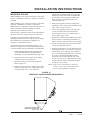
Bard Q48H1D Installation Instructions Manual
- Category
- Heat pumps
- Type
- Installation Instructions Manual

Manual 2100-521B
Page 1 of 48
Models:
Q24H1D Q30H1D
Q36H1D Q42H1D
Q48H1D Q60H1D
QTEC SERIES
PACKAGED HEAT PUMP
INSTALLATION
INSTRUCTIONS
Bard Manufacturing Company, Inc.
Bryan, Ohio 43506
Since 1914 . . . Moving ahead, just as planned.
Manual: 2100-521B
Supersedes: 2100-521A
File: Vol II Tab 14
Date: 02-06-12

Manual 2100-521B
Page 2 of 48
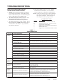
CONTENTS
Figures
Figure 1 Unit Dimensions.......................................7
Figure 2 Air Seal Under Unit ..................................8
Figure 3 Removal of Unit From Skid ......................8
Figure 4 Unit on Appliance Cart .............................9
Figure 5 Installation With Free Blow Plenum .......10
Figure 6 Ducted Application .................................10
Figure 7 Supply Duct Connections ...................... 11
Figure 8 Filter Location ........................................11
Figure 9 Optional Side Drain................................13
Figure 10 Standard Rear Drain ..............................13
Figure 11 Rear Drain (Top View)............................13
Figure 12A
Optional Rear Drain Kit ..........................14
Figure 12B
Optional Rear Drain Kit ..........................15
Figure 12C
Optional Rear Drain Kit ..........................16
Figure 12D
Optional Rear Drain Kit ..........................17
Figure 13A Unit Mounting - Method 1 .........................18
Figure 13B Unit Mounting - Method 2 .........................18
Figure 14 Removing Locking Screws from Wheels19
Figure 15 Component Location..............................20
Figure 16 Thermostat Plug Terminals ....................22
Figure 17 Dehum. Wiring w/"X" T-Stat ...................23
Figure 18 Dehum. Wiring w/"X" T-Stat & Demand....24
Figure 19 Dehum. Wiring w/"X" T-Stat & Vent Opt....25
Figure 20 Dehum. Wiring w/"E" T-Stat ...................26
Figure 21 Dehum. Wiring w/"G" T-Stat...................27
Figure 22 Dehum. Wiring w/"
I" T-Stat ....................28
Figure 23 Fresh Air Damper Removal....................33
Figure 24 QERV Removal......................................34
Figure 25 CO
2
Controller........................................36
Figure 26 Dehumidification Mode Circuit ...............37
Figure 27 Cooling Mode Circuit..............................38
Figure 28 Defrost Control Board ............................40
Figure 29 Control Disassembly ..............................44
Figure 30 Winding Test ..........................................44
Figure 31 Drip Loop ...............................................44
Figure 32 Fan Blade Setting ..................................45
Start Up
R-410A Refrigerant:
General ..................................................................29
Topping Off System Charge...................................29
Safety Practices.....................................................29
Description of Standard Equipment...........................30
Optional CFM ............................................................30
Important Installer Note .............................................30
Phase Monitor ...........................................................30
Three Phase Scroll Compressor Start Up
Information ................................................................30
Service Hints .............................................................31
Mist Eliminator Service..............................................31
Vent Options..............................................................32
Sequence of Operation .............................................35
Optional Climate Controls Sequence
of Operation ..................................................... 35 & 36
Refrigerant Tube Schematic for Reheat Coil.............36
Pressure Service Ports .............................................36
Defrost Cycle.............................................................39
Troubleshooting
Solid State Heat Pump Control Troubleshooting
Procedure..................................................................41
Checking Temperature Sensor..................................42
Troubleshooting GE ECM™ Blower Motors ........ 43-44
Fan Blade Setting Dimensions..................................45
Refrigerant Charge....................................................45
Pressure Charts ...................................................46-47
Getting Other Information and Publications
For more information, contact these publishers:......3
QT
EC General Information
QT
EC Model Nomenclature......................................4
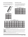
Shipping Damage ....................................................8
Unit Removal From Skid ..........................................8
Handling Unit After Removal From Skid ..................9
General ....................................................................9
Minimum Installation Height.....................................9
Duct Work.............................................................. 11
Filters ..................................................................... 11
Fresh Air Intake......................................................12
Service Light ..........................................................12
Condensate Drain..................................................12
Optional Rear Drain Kits ........................................12
Tables
Table 1 Factory Built-In Electric Heat Table ...........4
Table 2 Electrical Specifications ............................5
Table 2A Electrical Specifications ............................6
Table 3 Operating Voltage Range........................20
Table 4 Wall Thermostats ....................................22
Table 5 Troubleshooting ......................................41
Table 6 Temperature vs Resistance of
Temperature Sensor................................42
Table 7 Fan Blade Dimensions............................45
Table 8 Superheat at Compressor .......................45
Table 9 Indoor Blower Performance ....................45
Table 10 Cooling Pressure ....................................46
Table 11 Heating Pressure ....................................47
Table 12 Dehumidification Relay Logic Board .......48
Installation Instructions
Mounting the Unit...................................................19
Wiring — Main Power ............................................20
Wiring — Low Voltage Wiring ................................20
Low Voltage Connections ......................................21
General ..................................................................21

Manual 2100-521B
Page 3 of 48
GETTING OTHER INFORMATION AND PUBLICATIONS
These publications can help you install the air
conditioner or heat pump. You can usually find these at
your local library or purchase them directly from the
publisher. Be sure to consult current edition of each
standard.
National Electrical Code ..................... ANSI/NFPA 70
Standard for the Installation ............. ANSI/NFPA 90A
of Air Conditioning and Ventilating Systems
Standard for Warm Air ...................... ANSI/NFPA 90B
Heating and Air Conditioning Systems
Load Calculation for ....................... ACCA Manual J or
Winter and Summer Manual N
Air Conditioning
Low Pressure, Low Velocity ........ ACCA Manual D or
Duct System Design Manual Q
Winter and Summer
Air Conditioning
FOR MORE INFORMATION, CONTACT THESE
PUBLISHERS:
ACCA Air Conditioning Contractors of America
1712 New Hampshire Avenue
Washington, DC 20009
Telephone: (202) 483-9370
Fax: (202) 234-4721
ANSI American National Standards Institute
11 West Street, 13th Floor
New York, NY 10036
Telephone: (212) 642-4900
Fax: (212) 302-1286
ASHRAE American Society of Heating, Refrigeration,
and Air Conditioning Engineers, Inc.
1791 Tullie Circle, N.E.
Atlanta, GA 30329-2305
Telephone: (404) 636-8400
Fax: (404) 321-5478
NFPA National Fire Protection Association
Batterymarch Park
P.O. Box 9101
Quincy, MA 02269-9901
Telephone: (800) 344-3555
Fax: (617) 984-7057

Manual 2100-521B
Page 4 of 48
QT
EC
MODEL NOMENCLATURE
Q 36 H 1 D A 10 X X X X X X
SPECIAL UNITS |
D - Dehumidification
w/Hot Gas Reheat
REVISION |
VOLTS & PHASE |
A - 230/208/60/1
B - 230/208/60/3
C - 460/60/3
INTERNAL CONTROLS
X - Standard
• High Pressure Switch
• Low Pressure Switch
• Compressor Time Delay
E - Low Ambient Control
Q - Outdoor Thermostat
R - Low Ambient Control &
Outdoor Thermostat
COIL OPTIONS
X - Standard
CLIMATE CONTROL OPTIONS
X - None
E - Electronic/Prog/Man/Auto/Humidistat
G - Electronic/Non Prog/Man/Auto/Humidistat
I
- Electronic/Prog/Man/Auto/with CO
2
MODEL
NUMBER
Q - QT
EC
CAPACITY |
24 - 2 Ton
30 - 2½ Ton
36 - 3 Ton
42 - 3½ Ton
48 - 4 Ton
60 - 5 Ton
KW
0Z - 0KW
05 - 5KW
06 - 6KW
09 - 9KW
10 - 10KW
12 - 12KW
15 - 15KW
VENTILATION OPTIONS
X - Barometric Fresh Air Damper (Standard)
B - Blank-off Plate
R - Energy Recovery Ventilator w/Exhaust
P - Commercial Ventilator - Motorized w/Exhaust
Power Return
V - Commercial Ventilator - Motorized w/Exhaust
Spring Return
FILTER OPTIONS
X - 1-Inch Fiberglass
(Standard)
F - 2-Inch Fiberglass
P - 2-Inch Pleated
COLOR OPTIONS
X - Standard Beige
V - Platinum w/Slate
Front (Vinyl)
4 - Gray paint
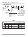
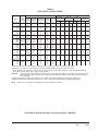
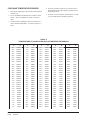
TABLE 1
FACTORY BUILT-IN ELECTRIC HEAT TABLE
sledoM
AD1H42Q
AD1H03QBD1H42QBD1H03QCD1H42QCD1H03Q
AD1H63Q
AD1H24Q
AD1H84Q
AD1H06Q
BD1H63Q
BD1H24Q
BD1H84Q
BD1H06Q
CD1H63Q
CD1H24Q
CD1H84Q
CD1H06Q
1-V0421-V8021-V0421-V8021-V0421-V8023-V0843-V0841-V0421-V8021-V0421-V8023-V084
WKHUTBHUTBHUTBHUTBHUTBHUTBHUTBHUTBHUTBHUTBHUTBHUTBHUTB
0.5083,61092,21
0.6005,02063,51005,02063,51005,02005,02005,02063,51005,02
0.9007,03000,32007,03000,32007,03007,03007,03000,32007,03
0.01076,23075,42 076,23075,42
0.21000,14007,03000,14
0.51 051,94068,63051,94068,63051,94
HEAT
PUMP
QT
EC
Series General Information

Manual 2100-521B
Page 5 of 48
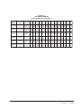
ELECTRICAL SPECIFICATIONS Continued on Page 6 TABLE 2A
1 Maximum size of the time delay fuse or HACR type circuit breaker for protection of field wiring conductors.
2 Based on 75°C copper wire. All wiring must conform to the National Electrical Code and all local codes.
3 These “Minimum Circuit Ampacity” values are to be used for sizing the field power conductors. Refer to the National Electric
Code (latest revision), article 310 for power conductor sizing.
CAUTION: When more than one field power conductor circuit is run through one conduit, the conductors must be derated. Pay
special attention to Note 8 of Table 310 regarding Ampacity Adjustment Factors when more than three conductors
are in a raceway.
4 Maximum KW that can operate with heat pump on is 10KW. Other 5KW energizes during emergency heating only.
5 Maximum KW that can operate with heat pump on is 9KW. Other 6KW energizes during emergency heating only.
NOTE: Reference Form 7960-582 for dehumidification model performance information.
TABLE 2
ELECTRICAL SPECIFICATIONS
tiucriCelgniS tiucriClauD
ledoM
detaR
stloV
esahPdna
dleiF.oN
rewoP
stiucriC
3 muminiM
tiucriC
yticapmA
1 mumixaM
esuFlanretxE
.rkrB.tkCro
2 dleiF
rewoP
eziSeriW
2 dnuorG
eriW
3 muminiM
tiucriC
yticapmA
1 mumixaM
esuFlanretxE
rekaerB.tkCro
2 dleiF
rewoP
eziSeriW
2 dnuorG
eziSeriW
A.tkC B.tkC A.tkC B.tkC A.tkC B.tkC A.tkC B.tkC
Z0AD1H42Q
50A
01A
1-802/032
1
1
2ro1
22
74
27
03
05
08
01
8
4
01
01
8
-
-
22
-
-
05
-
-
03
-
-
05
-
-
01
-
-
8
-
-
01
-
-
01
Z0BD1H42Q
60B
90B
3-802/032
1
1
1
71
53
44
02
53
54
21
8
8
21
01
01
-
-
-
-
-
-
-
-
-
-
-
-
-
-
-
-
-
-
-
-
-
-
-
-
Z0CD1H42Q
60C
90C
3-064
1
1
1
01
91
32
51
02
52
41
21
01
41
21
01
-
-
-
-
-
-
-
-
-
-
-
-
-
-
-
-
-
-
-
-
-
-
-
-
Z0AD1H03Q
50A
01A
1-802/032
1
1
2ro1
52
05
57
53
05
08
8
8
4
01
01
8
-
-
52
-
-
05
-
-
03
-
-
05
-
-
01
-
-
8
-
-
01
-
-
01
Z0BD1H03Q
60B
90B
21B
3-802/032
1
1
1
1
81
73
54
55
52
04
54
06
01
8
8
6
01
01
01
01
-
-
-
-
-
-
-
-
-
-
-
-
-
-
-
-
-
-
-
-
-
-
-
-
-
-
-
-
-
-
-
-
Z0CD1H03Q
60C
90C
21C
3-064
1
1
1
1
21
12
52
03
51
52
52
03
41
01
01
01
41
01
01
01
-
-
-
-
-
-
-
-
-
-
-
-
-
-
-
-
-
-
-
-
-
-
-
-
-
-
-
-
-
-
-
-
Z0AD1H63Q
50A
01A
4 51A
1-802/032
1
1
2ro1
2ro1
13
65
18
38
54
06
09
09
8
6
4
4
01
01
8
8
-
-
13
33
-
-
05
05
-
-
54
54
-
-
05
05
-
-
8
8
-
-
8
8
-
-
01
01
-
-
01
01
Z0BD1H63Q
60B
90B
5 51B
3-802/032
1
1
1
1
52
34
25
35
03
05
06
06
01
8
6
6
01
01
01
01
-
-
-
-
-
-
-
-
-
-
-
-
-
-
-
-
-
-
-
-
-
-
-
-
-
-
-
-
-
-
-
-
Z0CD1H63Q
60C
90C
5 51C
3-064
1
1
1
1
21
12
62
72
51
52
03
03
41
01
01
01
41
01
01
01
-
-
-
-
-
-
-
-
-
-
-
-
-
-
-
-
-
-
-
-
-
-
-
-
-
-
-
-
-
-
-
-

Manual 2100-521B
Page 6 of 48
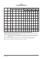
TABLE 2A
ELECTRICAL SPECIFICATIONS
(continued from Page 5)
tiucriCelgniS tiucriClauD
ledoM
detaR
stloV
esahPdna
dleiF.oN
rewoP
stiucriC
3 muminiM
tiucriC
yticapmA
1 mumixaM
esuFlanretxE
.rkrB.tkCro
2 dleiF
rewoP
eziSeriW
2 dnuorG
eriW
3 muminiM
tiucriC
yticapmA
1 mumixaM
esuFlanretxE
rekaerB.tkCro
2 dleiF
rewoP
eziSeriW
2 dnuorG
eziSeriW
A.tkC B.tkC A.tkC B.tkC A.tkC B.tkC A.tkC B.tkC
Z0AD1H24Q
50A
01A
4 51A
1-802/032
1
1
2ro1
2ro1
43
95
48
48
05
06
09
09
8
6
4
4
01
01
8
8
-
-
43
43
-
-
05
05
-
-
54
54
-
-
05
05
-
-
8
8
-
-
8
8
-
-
01
01
-
-
01
01
Z0BD1H24Q
60B
90B
5 51B
3-802/032
1
1
1
1
52
34
25
35
53
05
06
06
8
8
6
6
01
01
01
01
-
-
-
-
-
-
-
-
-
-
-
-
-
-
-
-
-
-
-
-
-
-
-
-
-
-
-
-
-
-
-
-
Z0CD1H24Q
60C
90C
5 51C
3-064
1
1
1
1
31
22
62
72
51
52
03
03
41
01
01
01
41
01
01
01
-
-
-
-
-
-
-
-
-
-
-
-
-
-
-
-
-
-
-
-
-
-
-
-
-
-
-
-
-
-
-
-
Z0AD1H84Q
50A
01A
4 51A
1-802/032
1
2ro1
2ro1
2ro1
83
36
88
88
05
07
09
09
8
6
3
3
01
8
8
8
-
83
83
83
-
52
05
05
-
05
05
05
-
52
05
05
-
8
8
8
-
01
8
8
-
01
01
01
-
01
01
01
Z0BD1H84Q
60B
90B
5 51B
3-802/032
1
1
1
1
92
74
65
65
04
05
06
06
8
8
6
6
01
01
01
01
-
-
-
-
-
-
-
-
-
-
-
-
-
-
-
-
-
-
-
-
-
-
-
-
-
-
-
-
-
-
-
-
Z0CD1H84Q
60C
90C
5 51C
3-064
1
1
1
1
51
42
82
82
02
52
03
03
21
01
01
01
21
01
01
01
-
-
-
-
-
-
-
-
-
-
-
-
-
-
-
-
-
-
-
-
-
-
-
-
-
-
-
-
-
-
-
-
Z0AD1H06Q 1 54 06 8 01 - - - - - - - -
50A
01A
5 51A
1-802/032
2ro1
2ro1
2ro1
07
59
59
09
001
001
4
3
3
8
8
8
54
54
54
52
05
05
06
06
06
52
05
05
8
8
8
01
8
8
01
01
01
01
01
01
Z0BD1H06Q 1 13 54 8 01 - - - - - - - -
90B
5 51B
3-802/032 1
1
85
85
06
06
6
6
01
01
-
-
-
-
-
-
-
-
-
-
-
-
-
-
-
-
Z0CD1H06Q 1 71 52 01 01 - - - - - - - -
90C
5 51C
3-064 1
1
13
13
53
53
8
8
01
01
-
-
-
-
-
-
-
-
-
-
-
-
-
-
-
-
1 Maximum size of the time delay fuse or HACR type circuit breaker for protection of field wiring conductors.
2 Based on 75°C copper wire. All wiring must conform to the National Electrical Code and all local codes.
3 These “Minimum Circuit Ampacity” values are to be used for sizing the field power conductors. Refer to the National Electric
Code (latest revision), article 310 for power conductor sizing.
CAUTION: When more than one field power conductor circuit is run through one conduit, the conductors must be derated. Pay
special attention to Note 8 of Table 310 regarding Ampacity Adjustment Factors when more than three conductors
are in a raceway.
4 Maximum KW that can operate with heat pump on is 10KW. Other 5KW energizes during emergency heating only.
5 Maximum KW that can operate with heat pump on is 9KW. Other 6KW energizes during emergency heating only.
NOTE: Reference Form 7960-582 for dehumidification model performance information.

Manual 2100-521B
Page 7 of 48
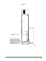
FIGURE 1
UNIT DIMENSIONS
Q24H1D
Q30H1D
Q36H1D
Q42H1D
Q48H1D
Q60H1D

Manual 2100-521B
Page 8 of 48
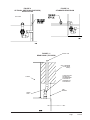
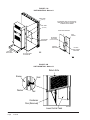
SHIPPING DAMAGE
Upon receipt of equipment, the carton should be
checked for external signs of shipping damage. The
skid must remain attached to the unit until the unit is
ready for installation. If damage is found, the receiving
party must contact the last carrier immediately,
preferably in writing, requesting inspection by the
carrier’s agent.
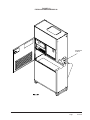
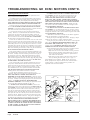
UNIT REMOVAL FROM SKID
FIGURE 3
REMOVAL OF UNIT FROM SKID
It is recommended that the unit not be removed from
the skid with a forklift since the air seal under the unit
could be damaged. See Figure 2.
The shipping brackets on each side of the unit must be
removed and discarded. See Figure 3-A. The return air
grille panel can be removed to provide a place to hold
the unit. The unit can be slid forward on the skid until
the front wheels hang over the edge of the skid. See
Figure 3-B. The unit can be tipped forward and slid
down the edge of the skid until the front wheels touch
the ground. See Figure 3-C. The wheels will not roll.
They are shipped from the factory locked so they will
not roll. The back of the skid will have to be held down
to keep it from tipping up. The skid can be slid out from
under the unit. The unit can then be set upright.
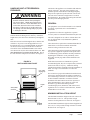
WARNING
This unit is heavy and requires more than one
person to handle and remove from the skid.
Check unit wheels to ensure that wheels are
locked before removing from skid. Extreme
caution must be taken to prevent injury to
personnel and damage to the unit.
FIGURE 2
AIR SEAL UNDER QT
EC
UNIT
Air Seal
A Shipping Brackets B Front Wheels Over Edge C Front Wheels On Floor
Hold
Skid
Down

Manual 2100-521B
Page 9 of 48
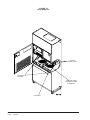
HANDLING UNIT AFTER REMOVAL
FROM SKID
FIGURE 4
UNIT ON APPLIANCE CART
The unit will have to be turned sideways and removed
from the skid to fit through a 36" doorway. If the door
height allows, the unit can be slid sideways through the
door.
If the unit can not be slid through the door, then the unit
will have to be put on a cart and tipped down to roll
through the door. It is recommended that an appliance
cart be used with a strap to hold the unit on the cart.
The wheels of the unit must be locked. If the wheels
were allowed to roll, the unit could roll off the cart. The
unit should always be carted from the left side. This is
the side where the compressor is located. See Figure 4.
The blade of the appliance cart should be slid under the
wheels of the unit. The strap of the appliance cart
should be placed around the unit and strapped tightly.
Help will be required to tip the unit back onto the cart.
The unit can be leaned far enough back to be rolled
through the door. Be careful when setting the unit back
up to keep from damaging the unit.
GENERAL
The equipment covered in this manual is to be installed
by trained, experienced service and installation
technicians.
A QWS-Series wall sleeve supplied as a separate
accessory must be ordered and installed with QTec unit.
The unit is designed for use with or without duct work.
For use without duct work, Plenum Box QPB42 is
recommended.
These instructions explain the recommended method to
install the air cooled self-contained unit and the
electrical wiring connections to the unit.
These instructions and any instructions packaged with
any separate equipment required to make up the entire
air conditioning system should be carefully read before
beginning the installation. Note particularly “Start
Procedure” and any tags and/or labels attached to the
equipment.
While these instructions are intended as a general
recommended guide, they do not supersede any national
and/or local codes in any way. Authorities having
jurisdiction should be consulted before the installation is
made. See Page 3 for information on codes and
standards.
Size of unit for a proposed installation should be based
on heat loss calculation made according to methods of
Air Conditioning Contractors of America (ACCA). The
air duct should be installed in accordance with the
Standards of the National Fire Protection Systems of
Other Than Residence Type, NFPA No. 90A, and
Residence Type Warm Air Heating and Air
Conditioning Systems, NFPA No. 90B. Where local
regulations are at a variance with instructions, installer
should adhere to local codes.
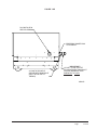
MINIMUM INSTALLATION HEIGHT
The minimum installation height of the unit with a Free
Blow Plenum is 8 ft. 6 in. This provides enough
clearance for the plenum to be removed. See Figure 5.
The minimum installation height for ducted applications
is 8 ft. 4½ in. This provides enough clearance to install
the duct work. See Figure 6.
WARNING
Exercise extreme caution when pushing the
unit on the rollers. Handle and push from the
lower 1/3 of the unit. Insure that debris is not
on the floor where the unit is to be moved on
the rollers. Failure to do so could result in the
unit tipping over and causing bodily injury and/
or damage to the unit.
QTEC UNIT
(Right Side)
APPLIANCE
CART
COMPRESSOR
STRAP

Manual 2100-521B
Page 10 of 48
FIGURE 6
DUCTED APPLICATION
FIGURE 5
INSTALLATION WITH FREE BLOW PLENUM

Manual 2100-521B
Page 11 of 48
DUCT WORK
Any heat pump is more critical of proper operating
charge and an adequate duct system than a straight air
conditioning unit. All duct work must be properly sized
for the design airflow requirement of the equipment.
Air Conditioning Contractors of America (ACCA) is an
excellent guide to proper sizing. All duct work or
portions thereof not in the conditioned space should be
properly insulated in order to both conserve energy and
prevent condensation or moisture damage. When duct
runs through unheated spaces, it should be insulated
with a minimum of one inch of insulation. Use
insulation with a vapor barrier on the outside of the
insulation. Flexible joints should be used to connect the
duct work to the equipment in order to keep the noise
transmission to a minimum.
The QT
EC
series heat pump has provision to attach a
supply air duct to the top of the unit. Duct connection
size is 12 inches x 20 inches. The duct work is field
supplied and must be attached in a manner to allow for
ease of removal when it becomes necessary to slide the
unit out from the wall for service. See Figure 7 for
suggested attachment method.
NOTE: Unit cabinet, supply air duct and free blow
plenum are approved for “0” clearance to
combustible material.
The QT
EC
series heat pumps are designed for use with
free return (non-ducted) and either free blow with the
use of QPB Plenum Box or a duct supply air system.
The QPB and QPBHW Plenum Box mounts on top of
the unit and has both vertically and horizontally
adjustable louvers on the front discharge grille.
For hot water coil option a QPBHWxx-F for free blow
or QPBHWxx-D for ducted airflow is used.
When used with a ducted supply, a QCX Cabinet
Extension can be used to conceal the duct work above
the unit to the ceiling. This extends 20" above the unit
for a total height above the floor of 10'-7/8". The unit is
equipped with a variable speed indoor blower motor
which increases in speed with an increase in duct static
pressure. The unit will therefore deliver proper rated
airflow up to the maximum ESP shown in Table 9.
However, for quiet operation of the air system, the duct
static should be kept as low as practical, within the
guidelines of good duct design.
FILTERS
Two 1-inch throw away filters [(1) 16x16 and (1)
16x20] are supplied with each unit. The filters slide into
filter brackets. Refer to Figure 8.
The filters are serviced from the inside of the building
by opening the hinged door. This door is attached by
1/4 turn fasteners and one locking latch.
The internal filter brackets are adjustable to
accommodate 2-inch filters. The tabs for the 1-inch
filters must be bent down to allow the 2-inch filters to
slide in place.
FIGURE 7
SUPPLY DUCT CONNECTIONS
SUPPLY DUCT
TO BE FIELD
SUPPLIED
ATTACHMENT
SCREWS TO
BE FIELD
SUPPLIED
ROOM SIDE OF
QT
EC UNIT
DUCT FLANGE
PROVIDED WITH
UNIT
FIGURE 8
FILTER LOCATION
FILTERS
RETURN AIR
GRILLE

Manual 2100-521B
Page 12 of 48
FRESH AIR INTAKE
This unit is equipped with a fresh air damper assembly.
The damper blade is locked in the closed position when
the unit is shipped from the factory. To allow the
damper to operate, remove the two plastic locking pins,
one on each end of the blade. This will allow for
maximum fresh airflow. The damper blade will now
open when the indoor blower is operating. If less than
maximum fresh airflow is required, reinsert the plastic
pins to limit damper blade opening to desired level.
Two extra pins are provided (taped to the inside of the
assembly) which may be used to hold the blade in some
position other than minimum or maximum position.
This fresh air assembly is located in the rear of the unit
and to gain access to make these adjustments remove
the air filter service door.
All capacity, efficiency and cost of operation
information as required for Department of Energy
“Energyguide” Fact Sheets are based upon the fresh air
blank-off plate in place and is recommended for
maximum energy efficiency.
The blank-off plate is available upon request from the
factory and is installed in place of the fresh air damper
shipped with each unit.
For details on energy recovery ventilation see Page 31
for details.
SERVICE LIGHT
The unit is equipped with a service light which signals
the user that service is required. The light is located in
the upper control panel and is visible only when the
hinged service/filter access door is open.
The Service Unit light indicates that the unit has been
shut off by a high or low pressure device. This indicates
that the unit needs to be serviced. See Page 29 for
details.
CONDENSATE DRAIN
There are two drain connections on the unit. The rear
drain is the primary drain, and is located on the right
lower rear panel of the unit. The optional side drain is
located on the bottom right side of the unit. The side
drain is shipped with a plug installed.
The side drain requires a water trap for proper drainage.
See Figure 9. The drain can be routed through the floor
or through the wall. If the drain is to be routed through
an unconditioned space, it must be protected from
freezing. The drain line must be able to be removed
from the unit if it is necessary to remove the unit from the
wall. When the side drain is used, the plug must be
removed and installed in the rear drain outlet.
The rear drain can be used with wall thickness of up to
10 inches where a water trap can be installed between
the unit and the interior wall. See Figure 10. The trap
cannot extend beyond the edge of the unit or it will
interfere with the wall mounting bracket. The drain can
be routed through the floor or through the wall. If the
drain is routed through the wall, the drain line must be
positioned such that it will not interfere with the sleeve
flange or the grille. See Figure 11. If the drain is to be
routed through an unconditioned space, it must be
protected from freezing.
OPTIONAL REAR DRAIN KITS
Optional Rear Drain Kit, Bard Model QCDS48A, is
also available for these products. The optional rear
drain kit offers multiple benefits that include the
following:
• Allows unit to be rolled away from the sleeve
without having to disconnect any hard plumbing
connections.
• Allows indoor coil condensate to be easily
connected to Rear Drain Box while bypassing the
outdoor coil drain pan. This aids in minimizing the
potential for biological growth to occur by
minimizing the standing water and exposing it to
warm temperatures.
See Figures 12A, 12B, 12C and 12D.
The drain box permanently mounts onto the wall sleeve
and is then either piped directly outdoors, or can be
piped vertically. The Q/Tec unit is then equipped with
fittings on the rear of the unit that slide into the drain
box as it is wheeled towards the wall sleeve.
NOTE: On models equipped with a refrigerant
subcooler in the lower drain pan may experience a 2-
3% decrease in cooling performance and efficiency
when the indoor condensate is routed around the
outdoor coil drain pan/subcooler assembly. Unit rated
performance and efficiency are with the indoor
condensate routed to the outdoor coil pan.
There is also a heated version of the rear drain box
available (Model #QCDS48H) for installation in
northern climates where freezing may occur.

Manual 2100-521B
Page 13 of 48
FIGURE 9
OPTIONAL SIDE DRAIN (SIDE VIEW)
INSTALLATION
QTEC UNIT
FIGURE 10
STANDARD REAR DRAIN
WATER
TRAP
FIGURE 11
REAR DRAIN (TOP VIEW)
WALL (MAXIMUM
10" FOR REAR
DRAIN)
COUPLINGS NOT
SHOWN BUT
RECOMMENDED
FOR EASE OF
REMOVABILITY
FOR SERVICE.
SLEEVE
DRAIN LINE
WALL
BRACKET
UNIT

Manual 2100-521B
Page 14 of 48
MIS-2469
DRAIN BOX
WALL SLEEVE
OVERFLOW TUBE
CAULK AROUND TUBE
FIGURE 12A

Manual 2100-521B
Page 15 of 48
SUPPLIED WITH DRAIN BOX KIT
3/4" PLASTIC PIPE NIPPLE
HORIZONTAL TO FLOOR)
(TIGHTEN THREADS SO TEE IS
THREADS)
(APPLY TEFLON TAPE TO
REAR DRAIN CONNECTION IN
Q/Tec PRODUCT
1/2" SLIP X 1/2" SLIP X 3/4" NPT
TEE SUPPLIED WITH DRAIN BOX KIT
PLUG INSTALLED IN
SIDE Q/Tec DRAIN
MIS-2470
FIGURE 12B
IMPORTANT !

Manual 2100-521B
Page 16 of 48
REMOVE KNOCK-OUT FOR
INDOOR DRAIN HOSE CONNECTOR
MIS-2471
FIGURE 12C
(If Used)

Manual 2100-521B
Page 17 of 48
MIS-2472
DRAIN HOSE FROM INDOOR
DRAIN PAN.
MOVE HOSE FROM ATTACHMENT IN
LOWER DRAIN PAN AND SLIDE ONTO
DRAIN BOX BARB FITTING, SECURING
WITH SUPPLIED CLAMP IF OUTDOOR
PAN IS BYPASSED. ( WILL REDUCE RISK
OF ALGAE GROWTH IN THE OUTDOOR
PAN BUT AT A SLIGHT COOLING
PERFORMANCE REDUCTION OF 2-3% )
FIGURE 12D

Manual 2100-521B
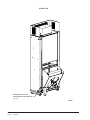
Page 18 of 48
Washer
Sleeve
Stud
MIS-2689
Nut
Lower Control Panel
Condenser
Door (Removed)
Return Grille
FIGURE 13A
UNIT MOUNTING - Method 1
BOTTOM
TRIM PIECE
BOTTOM TRIM
EXTENSION
MOUNTING
BRACKET
SIDE TRIM
(2 PCS.)
SIDE TRIM
(2 PCS.)
CABINET
SIDE PANEL
ENLARGED VIEW OF MOUNTING
BRACKET SHOWING SLEEVE TO
CABINET ATTACHMENT
MOUNTING BRACKET
#8 SCREW
PROVIDED
(LIGHT COLOR)
WALL
SLEEVE
#10 HEX
HEAD SCREW
PROVIDED
FIGURE 13B
UNIT MOUNTING - Method 2

Manual 2100-521B
Page 19 of 48
INSTALLATION INSTRUCTIONS
MOUNTING THE UNIT
When installing a QT
EC
unit near an interior wall on the
left side, a minimum of 8 inches is required; 12 inches is
preferred.
When installing a QT
EC
unit near an interior wall on the
right side, a minimum of 18 inches is required as
additional space is required to connect the side drain. If
the rear condensate drain kit QCDS48 is used the
minimum can be reduced to 8 inches.
This clearance is required to allow for the attachment of
the unit to the sleeve and side trim pieces to the wall.
This unit is to be secured to the wall sleeve with
mounting brackets provided. The unit itself, the supply
duct and the free blow plenum are suitable of “0”
clearance to combustible material.
Following are the steps for mounting the QT
EC
. For
reference see Figure 13A for external mounting bracket
or 13B for internal bolt secured bracket (recommended).
1. Attach mounting brackets to the wall sleeve with
screws provided. Either use external mounting
bracket (Fig. 13A) or internal bolt bracket (Fig. 13B).
2. Position the unit in front of the sleeve with the
condenser section toward the sleeve.
3. Remove the locking screws from the wheels.
Refer to Figure 14.
4. Roll the unit into the sleeve. Make sure to check
both sides of the unit as it is being rolled to keep
it centered in the sleeve. Also check the
alignment to the mounting brackets. This unit
must be level from side to side. If adjustments
are necessary, shim up under the rollers with
sheets of steel or any substance that is not
affected by moisture.
5. Make sure the gasket on the rear of the unit is
touching the sleeve across the top and down both
sides. This is a rain water seal.
6. Secure the mounting brackets to the unit with
screws provided, #10 hex head sheet metal
screws (Figure 13A) or use nut and washer to
secure sleeve (Figure 13B).
7. Bottom trim extensions are provided for use when
wall is less than 14 inches but greater than 10.5
inches. Secure to wall with screws (not provided).
8. Attach the bottom trim piece to the unit with the
screws provided (dark colored).
9. Position side trim pieces to wall and attach with
field supplied screws. There are two long pieces
and two short pieces supplied. The long pieces
are to enclose the gap behind the unit. The short
pieces are to fill the gap behind the cabinet
extension or the free blow plenum box. They
may be cut to suit your ceiling height or overlap
the unit side trim. There is sufficient length to
trim up to a 10'2" ceiling.
NOTE: If the exterior wall thickness is between 5
inches to 10.5 inches, a side trim extension
piece kit, model QSTX42, is available.
REMOVE SCREWS FROM
WHEELS BEFORE ROLLING
INTO PLACE
FIGURE 14
REMOVING LOCKING SCREWS FROM WHEELS

Manual 2100-521B
Page 20 of 48
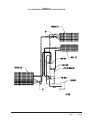
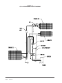
NOTE: The voltage should be measured at the field
power connection point in the unit and while the
unit is operating at full load (maximum
amperage operating condition).
The standard Climate Control Option X is a remote
thermostat connection terminal block. See Figure 17 for
wiring diagram. Compatible thermostats are listed in
Table 4.
The Climate Control Option E is an electronic,
programmable thermostat and a humidistat. The sub
base of the thermostat and the humidistat are factory
wired to the front panel of the unit. See Figure 19 for
wiring diagram. Compatible for use with Energy
Recovery Ventilator or Ventilator.
The Climate Control Option G is an electronic,
non-programmable thermostat and humidistat. The
subbase of the thermostat is factory wired to the front
panel of the unit. This option is compatible for use with
the optional CS2000A* Energy Control Monitor and a
terminal block is provided for connection to the
CS2000A*. See Figure 20 for wiring diagram.
Compatible for use with Energy Recovery Ventilator or
Ventilator.
The Climate Control Option I is an electronic,
programmable thermostat, humidistat and a CO
2
controller. The subbase of the thermostat and CO
2
controller are factory wired to the front panel of the unit.
See Figure 21 for wiring diagram.
NOTE: On options X and G the CS2000A* (or other
field provided means to control ventilation) must
be used if any of the mechanical (motorized)
ventilation options are installed.
WIRING – MAIN POWER
Refer to the unit rating plate and/or Table 2/2A for wire
sizing information and maximum fuse or “HACR Type”
circuit breaker size. Each unit is marked with a
“Minimum Circuit Ampacity”. This means that the
field wiring used must be sized to carry that amount of
current. Depending on the installed KW of electric
heat, there may be two field power circuits required. If
this is the case, the unit serial plate will so indicate. All
models are suitable only for connection with copper
wire. Each unit and/or wiring diagram will be marked
“Use Copper Conductors Only”. These instructions
MUST BE adhered to. Refer to the National Electrical
Code (NEC) for complete current carrying capacity data
on the various insulation grades of wiring material. All
wiring must conform to NEC and all local codes.
The electrical data lists fuse and wire sizes (75°C
copper) for all models, including the most commonly
used heater sizes. Also shown are the number of field
power circuits required for the various models with
heaters.
The unit rating plate lists a “Maximum Time Delay
Relay Fuse” or “HACR Type” circuit breaker that is to
be used with the equipment. The correct size must be
used for proper circuit protection, and also to assure that
there will be no nuisance tripping due to the momentary
high starting current of the compressor motor.
The disconnect access door on this unit may be locked
to prevent unauthorized access to the disconnect.
See Start Up section for information on three phase
scroll compressor start-ups.
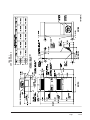
The field wiring connections are located behind the top
and hinged panel in the circuit breaker panel. See
Figure 15.
WIRING – LOW VOLTAGE WIRING
230/208V, 1 PHASE AND 3 PHASE EQUIPMENT
DUAL PRIMARY VOLTAGE TRANSFORMERS.
All Equipment leaves the factory wired on 240V tap.
For 208V operation, reconnect from 240V to 208V tap.
The acceptable operating voltage range for the 240 and
208V taps are as noted in Table 3.
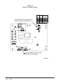
TABLE 3
OPERATING VOLTAGE RANGE
PATEGNAR
V042612–352
V802781–022
DEHUMIDIFICATION
CONTROL
THERMOSTAT
& HUMIDISTAT
CONTROLS
ELECTRIC
HEATERS
CIRCUIT BREAKER
PANEL &
CONTROLS
INDOOR
BLOWER
REMOTE
THERMOSTAT
TERMINAL
BLOCK
SIDE FIELD WIRE
ENTRANCE
LOWER
CONTROL
PANEL
FIGURE 15
COMPONENT LOCATION
Page is loading ...
Page is loading ...
Page is loading ...
Page is loading ...
Page is loading ...
Page is loading ...
Page is loading ...
Page is loading ...
Page is loading ...
Page is loading ...
Page is loading ...
Page is loading ...
Page is loading ...
Page is loading ...
Page is loading ...
Page is loading ...
Page is loading ...
Page is loading ...
Page is loading ...
Page is loading ...
Page is loading ...
Page is loading ...
Page is loading ...
Page is loading ...
Page is loading ...
Page is loading ...
Page is loading ...
Page is loading ...
-
 1
1
-
 2
2
-
 3
3
-
 4
4
-
 5
5
-
 6
6
-
 7
7
-
 8
8
-
 9
9
-
 10
10
-
 11
11
-
 12
12
-
 13
13
-
 14
14
-
 15
15
-
 16
16
-
 17
17
-
 18
18
-
 19
19
-
 20
20
-
 21
21
-
 22
22
-
 23
23
-
 24
24
-
 25
25
-
 26
26
-
 27
27
-
 28
28
-
 29
29
-
 30
30
-
 31
31
-
 32
32
-
 33
33
-
 34
34
-
 35
35
-
 36
36
-
 37
37
-
 38
38
-
 39
39
-
 40
40
-
 41
41
-
 42
42
-
 43
43
-
 44
44
-
 45
45
-
 46
46
-
 47
47
-
 48
48


Bard Q48H1D Installation Instructions Manual
- Category
- Heat pumps
- Type
- Installation Instructions Manual
Ask a question and I''ll find the answer in the document
Finding information in a document is now easier with AI
Related papers
-
Bard MULTI-TEC W24ABP Series Literature Assembly
-
Bard QW Series Literature Assembly
-
Bard W36AB-C Series Installation Instructions Manual
-
Bard QA601D Installation Instructions Manual
-
Bard QTEC QH482 Installation Instructions Manual
-
-
-
Bard 2100-778 User guide
-
Bard Q-TEC Q24H1 User manual
-
Other documents
-
Unbranded H5HK009S-01, 9KW, 1-Stage, 480 VAC, 3-Phase Product information
-
-
-
Broan VQ6SE, Single Phase Product information
-
-
-
-
Broan Q4SE Installation guide
-
-