Page is loading ...

Page 1
MODEL QTRE100S
WARNING
TO REDUCE THE RISK OF FIRE, ELECTRIC SHOCK, OR IN-
JURY TO PERSONS, OBSERVE THE FOLLOWING:
1. Use this unit only in the manner intended by the manufacturer.
If you have questions, contact the manufacturer at the address
or telephone number listed in the warranty.
2. Before servicing or cleaning unit, switch power off at service
panel and lock the service disconnecting means to prevent
power from being switched on accidentally. When the service
disconnecting means cannot be locked, securely fasten a
prominent warning device, such as a tag, to the service panel.
3. Installation work and electrical wiring must be done by a qualified
person(s) in accordance with all applicable codes and standards,
including fire-rated construction codes and standards.
4. Sufficient air is needed for proper combustion and exhausting
of gases through the flue (chimney) of fuel burning equipment
to prevent backdrafting. Follow the heating equipment manufac-
turer’s guideline and safety standards such as those published
by the National Fire Protection Association (NFPA), and the
American Society for Heating, Refrigeration and Air Condition-
ing Engineers (ASHRAE), and the local code authorities.
5. When cutting or drilling into wall or ceiling, do not damage
electrical wiring and other hidden utilities.
6. Ducted fans must always be vented to the outdoors.
7. Acceptable for use over a tub or shower when connected to a
GFCI (Ground Fault Circuit Interrupter) - protected branch circuit.
8. This unit must be grounded.
CAUTION
1. For general ventilating use only. Do not use to exhaust hazard-
ous or explosive materials and vapors.
2. This product is designed for installation in flat ceilings only. DO
NOT MOUNT THIS PRODUCT IN A WALL.
3. To avoid motor bearing damage and noisy and/or unbalanced
impellers, keep drywall spray, construction dust, etc. off power
unit.
4. Please read specification label on product for further information
and requirements.
HUMIDITY SENSING FAN
READ AND SAVE THESE INSTRUCTIONS
CLEANING & MAINTENANCE
Installer: Leave this manual with the homeowner.
For quiet and efficient operation, long life, and attractive appear-
ance - lower or remove grille and vacuum interior of unit with the
dusting brush attachment.
The motor is permanently lubricated and never needs oiling. If the
motor bearings are making excessive or unusual noises, replace
the motor / blower wheel assembly.
SENSOR CLEANING
The humidity sensor is mounted in the control housing. The sensor
will operate most reliably when cleaned occasionally as follows:
1. Disconnect power at service entrance.
2. Remove the grille. Use a dry dustcloth, clean toothbrush,
or lightly vacuum to clean sensor and grille. DO NOT USE
ABRASIVE CLOTH, STEEL WOOL PADS, OR SCOURING
POWDERS.
3. DO NOT USE cleaning sprays, solvents, or water on or near
the sensor!
OPERATION
The humidity control and fan can be operated separately. Use a
1- or 2-function wall control. Do not use a dimmer switch to operate
the humidity control. See “Connect Wiring” for details.
SENSOR OPERATION
The humidity-sensing
fan uses a sophisticated humidity sensor
that responds to: (a) rapid to moderate increases in humidity or (b)
humidity above a set-point. The humidity sensor may occasionally
turn the fan ON when environmental conditions change.
MANUAL ON WITH TIMED OFF
The humidity sensing fan has an additional operation feature. For
odor or vapor control, the fan can be energized by cycling the
power switch. Once the fan has been energized in this manner, it
will remain on for 20 minutes.
To manually energize the fan:
1. If fan power switch is already ON, proceed to Step 2; otherwise,
turn power switch ON for more than 1 second.
2. Turn fan power switch OFF for less than 1 second.
3. Turn fan power switch back ON and fan will turn ON.
To register this product visit: www.broan.com

Page 2
MODEL QTRE100S
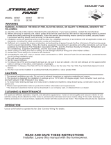
TYPICAL INSTALLATIONS
Housing mounted to
I-joists.
Housing mounted anywhere be-
tween trusses using hanger bars.
PLAN THE INSTALLATION
1. Choose the
installation
location.
The location of
your humidity
sensing fan is
very important.
Use the follow-
ing guidelines
for best opera-
tion:
Housing mounted anywhere between
I-joists using hanger bars.
Housing mounted to joists.
Housing mounted anywhere between
joists using hanger bars.
Housing mounted anywhere be-
tween trusses using hanger bars.
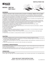
INSTALL HOUSING &
DUCT
1a. Mount
housing
to joist
or I-joist.
Use a pliers to
bend housing
TABS out to
90
0
. Hold hous-
ing in place so
that the hous-
ing tabs con-
tact the bottom
of the joist.
The housing
mounts with
four (4) screws
or nails. Screw
or nail housing
to joist through
lowest holes in
each mount-
ing flange,
then through
highest holes.
SPACER
(use for mounting to I-Joist)
TABS
I-JOIST
NOTE: Mounting to I-JOIST (shown) requires use of
SPACERS (included) between the highest hole of each
mounting flange and the I-joist.
OR
• Locate unit above (GFCI protected circuit required) or
within 5 feet of shower head.
• Locate unit away from heating or cooling sources
which can affect humidity levels.
• Do not locate near window. Unit may respond to the
outdoor humidity level.
• Unit must be installed in ceiling to properly sense
moisture.
• Locate unit only on flat ceilings up to 12 feet high for
proper sensing.
• The ducting from this fan to the outside of the building
has a strong effect on the air flow, noise and energy
use of the fan. Use the shortest, straightest duct rout-
ing possible for best performance, and avoid installing
the fan with smaller ducts than recommended. Insula-
tion around the ducts can reduce energy loss and
inhibit mold growth. Fans installed with existing ducts
may not achieve their rated airflow.
• Use a roof cap or wall cap that has a built-in damper
to reduce backdrafts.
2. Plan the wiring.
• Plan to supply the unit with proper line voltage and
appropriate power cable. Power cable should be
routed to the switch box first and then to the unit
(See “CONNECT WIRING” on page 3).
• Do not operate this unit with a speed control.
Damage to the sensor unit will result.
*Purchase
separately.
INSULATION*
(Place around and
over Fan Housing.)
ROOF CAP*
(with built-in
damper)
FAN
HOUSING
POWER
CABLE*
4-IN. ROUND
DUCT*
4-IN.
ROUND
ELBOWS*
Seal gaps
around
Housing.
Seal duct
joints with
tape.
OR
Keep duct
runs short.
WALL CAP*
(with built-in
damper)

Page 3
MODEL QTRE100S
1b. Mount housing anywhere between
trusses, joists, or I-joists using hanger
bars.
Sliding hanger bars are provided to allow for accurate posi-
tioning of housing anywhere between framing. They can be
used on all types of framing (I-joist, standard joist, and truss
construction) and span up to 24”.
Attach the MOUNTING CHANNELS to the housing using
the SCREWS supplied. Make sure TABS face “up” as shown.
Use the set of channel mounting holes (marked “STD”) to
mount the housing flush with the bottom of the drywall. Use
the other set of holes (not marked) to mount the housing
flush with the top of the drywall.
HANGER
BAR (4)
SCREWS (4)
Extend HANGER BARS to the width of the framing.
Hold ventilator in place with the hanger bar tabs wrapping
around the BOTTOM EDGE OF THE FRAMING.
NAIL ventilator to framing or fasten with screws (not provided)
through HOLES near nails.
*
To ensure a noise-free mount: Secure hanger bars together
with SCREWS or use a pliers to crimp mounting channels
tightly around hanger bars.
*
SCREW (2)
HOLE FOR OPTIONAL
SCREW MOUNTING (4)
MOUNTING
CHANNEL (2)
NAIL (4)
BOTTOM EDGE
OF FRAMING
4. Connect electrical wiring.
Run 120 VAC house wiring to installation location. Use
proper UL approved connector to secure house wiring to
wiring plate. Connect wires as shown in wiring diagrams.
CONNECT WIRING
ON / OFF SWITCH
(PURCHASE SEPARATELY)
ON / OFF
SWITCH
120
VAC
LINE
IN
SWITCH BOX
WHT
GRD
BLK
WHT
UNIT
ORG
BLK
WHT
GRD
WHT
BLK
WHT
BRN
HUMIDITY
CONTROL
FAN
2. Attach damper/
duct connector.
Snap damper / duct con-
nector onto housing. Make
sure connector is flush
with top of housing and
damper flap falls closed.
3. Install
4-inch round duc-
twork.
Connect 4-inch round
ductwork to damper / duct
connector. Run ductwork
to a roof cap or wall cap.
Tape all ductwork con-
nections to make them
secure and air tight.
120
VAC
LINE
IN
SWITCH BOX
WHT
GRD
WHT
UNIT
BLK
WHT
GRD
WHT
BLK
WHT
HUMIDITY
CONTROL
FAN
RED
BLK
ORG
BRN
MODEL 68W, 2-FUNCTION CONTROL
(PURCHASE SEPARATELY)
COM
HUMIDITY
CONTROL
(AUTO/OFF)
FAN
(ON/OFF)
WIRING OPTION #1 - Allows fan to operate in automatic mode or manual
mode (for odor control) by cycling ON/OFF switch.
WIRING OPTION #2 - Fan can be turned ON, OFF, or set to operate automati-
cally.
TAB

Page 4
MODEL QTRE100S
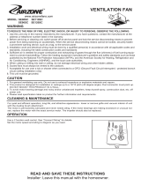
SERVICE PARTS
99045486A
Key No. Part No. Description
1 97016466 Housing
2 97016449 Duct Connector - 4”
3 98010102 Wiring Plate
4 99170245 Screw, #8-18 X .375
5 97017085 Wire Panel/Harness Assembly
6 97020044 Blower Assembly
(includes key no. 12)
7 97017674 Control Assembly
8 97017420 Grille Assembly
(includes key nos. 8 & 9)
9 99140199 Grille Spring (2 req’d)
10 97018014 Spacer (2 supplied)
11 QTHB1 Hanger Bar Kit
12 99420665 Thumbscrew, #8-18 x .375
Order service parts by “Part No.” - not by “Key No.”
INSTALL GRILLE
6. Finish ceiling.
Install ceiling material. Cut out around housing.
7. Attach grille to
housing.
Squeeze grille springs
and insert them into slots
on each side of housing.
8. Push grille against
ceiling.
WARRANTY
Replacement parts
can be ordered on
our website. Please
visit us at www.
broan.com
SERVICE NOTE
To remove Blower Assembly:
Unplug motor. Remove
thumbscrew (12) from motor
plate flange. Find the single
TAB on the motor plate
(located next to the receptacle).
Push up near motor plate tab
while pushing out on side of
housing. Or insert a straight-
blade screwdriver into slot in
housing (next to tab) and twist
screwdriver.
BROAN THREE YEAR LIMITED WARRANTY
Broan warrants to the original consumer purchaser of its products that such
products will be free from defects in materials or workmanship for a period of three
years from the date of original purchase. THERE ARE NO OTHER WARRANTIES,
EXPRESS OR IMPLIED, INCLUDING, BUT NOT LIMITED TO, IMPLIED WAR-
RANTIES OF MERCHANTABILITY OR FITNESS FOR A PARTICULAR PURPOSE.
During this three-year period, Broan will, at its option, repair or replace, without
charge, any product or part which is found to be defective under normal use
and service.
THIS WARRANTY DOES NOT EXTEND TO FLUORESCENT LAMP STARTERS AND
TUBES. This warranty does not cover (a) normal maintenance and service or (b)
any products or parts which have been subject to misuse, negligence, accident,
improper maintenance or repair (other than by Broan), faulty installation or instal-
lation contrary to recommended installation instructions.
The duration of an implied warranty is limited to the three-year period as specified
for the express warranty. Some states do not allow limitation on how long an
implied warranty lasts, so the above limitation may not apply to you.
BROAN’S OBLIGATION TO REPAIR OR REPLACE, AT BROAN’S OPTION, SHALL
BE THE PURCHASER’S SOLE AND EXCLUSIVE REMEDY UNDER THIS WAR-
RANTY. BROAN SHALL NOT BE LIABLE FOR INCIDENTAL, CONSEQUENTIAL
OR SPECIAL DAMAGES ARISING OUT OF OR IN CONNECTION WITH PRODUCT
USE OR PERFORMANCE. Some states do not allow the exclusion or limitation of
incidental or consequential damages, so the above limitation may not apply to you.
This warranty gives you specific legal rights, and you may also have other rights,
which vary from state to state. This warranty supersedes all prior warranties.
To qualify for warranty service, you must (a) notify Broan at the address or tele-
phone number stated below, (b) give the model number and part identification and
(c) describe the nature of any defect in the product or part. At the time of request-
ing warranty service, you must present evidence of the original purchase date.
Broan-NuTone LLC Hartford, Wisconsin www.broan.com 800-558-1711

Página 8
MODELO QTRE100S
PIEZAS DE REPUESTO
99045486A
Clave n.º Pieza n.º Descripción
1 97016466 Cubierta
2 97016449 Conector de conductor, 10,2 cm (4 pulg.)
3 98010102 Placa de cableado
4 99170245 Tornillo n.º 8-18 x 0.375
5 97017085 Conjunto del panel de cableado/arnés
6 97020044 Conjunto del ventilador
(incluye clave n.º 12)
7 97017674 Conjunto de control
8 97017420 Conjunto de la rejilla
(incluye las claves n.º 8 y 9)
9 99140199 Resorte de la rejilla (se requieren 2)
10 97018014 Separador (se suministran 2)
11 QTHB1 Juego de barra de suspensión
12 99420665 Tornillo de mariposa n.º 8-18 x 0.375
Al hacer el pedido de una pieza de servicio se debe especificar
el número de la pieza (no el número de la clave).
INSTALE LA REJILLA
6. Termine el cielo raso.
Instale el material del cielo raso. Recorte alrededor de la
cubierta.
7. Acople la rejilla a
la cubierta.
Apriete los resortes de la
rejilla e insértelos en las
ranuras que se encuen-
tran a cada lado de la
cubierta.
8. Empuje la rejilla
contra el cielo
raso.
GARANTÍA
Se pueden hacer
los pedidos de las
piezas de repuesto
en nuestro sitio web.
Le rogamos visitar-
nos a
www.broan.com
NOTA DE SERVICIO
Para desmontar el conjunto del
ventilador: Desenchufe el motor.
Saque el tornillo de mariposa (12)
de la brida de la placa del motor.
Localice la LENGÜETA única de
la placa del motor (se encuentra
junto al receptáculo). Empuje hacia
arriba cerca de la lengüeta de la
placa del motor al mismo tiempo
que empuja hacia afuera el costado
de la cubierta. O bien, introduzca
un destornillador de punta recta en
la ranura de la cubierta (junto a la
lengüeta) y gire el destornillador.
GARANTÍA LIMITADA DE TRES AÑOS DE BROAN
Broan garantiza al consumidor comprador original de sus productos que tales
productos estarán libres de defectos en materiales o mano de obra durante un
período de tres años a partir de la fecha de la compra original. NO EXISTEN OTRAS
GARANTÍAS, EXPRESAS NI IMPLÍCITAS, INCLUIDAS (PERO SIN LIMITARSE
A) GARANTÍAS IMPLÍCITAS DE COMERCIALIZACIÓN O IDONEIDAD PARA UN
PROPÓSITO PARTICULAR.
Durante este período de tres años, Broan, a su criterio, reparará o reemplazará,
sin cargo alguno, cualquier pieza o producto que se encuentre defectuoso bajo
condiciones normales de uso y servicio.
ESTA GARANTÍA NO SE EXTIENDE A ARRANCADORES NI A TUBOS DE LAS
LÁMPARAS FLUORESCENTES. Esta garantía no cubre (a) mantenimiento y
servicio normales ni (b) ningún producto o piezas que se hayan sometido a uso
inadecuado, negligencia, accidente, mantenimiento o reparación inadecuada (no
hecha por Broan), instalación incorrecta o instalación que vaya en contravención
de las instrucciones de instalación recomendadas.
La duración de una garantía implícita se limita al período de tres años como se
especifica para la garantía explícita. Algunos estados no permiten la limitación de
la duración de una garantía implícita, de manera que las limitaciones antedichas
pueden no aplicar a usted.
LA OBLIGACIÓN DE BROAN DE REPARAR O REEMPLAZAR, A OPCIÓN DE
BROAN, SERÁ EL ÚNICO Y EXCLUSIVO RECURSO DEL COMPRADOR BAJO
ESTA GARANTÍA. BROAN NO SERÁ RESPONSABLE POR DAÑOS INCIDENTALES,
RESULTANTES O ESPECIALES QUE SURJAN DE, O EN RELACIÓN CON, EL USO
O RENDIMIENTO DEL PRODUCTO. Algunos estados no permiten la exclusión o
la limitación de daños incidentales o resultantes, de manera que es posible que
la limitación antedicha no se aplique en su caso.
Esta garantía le da derechos legales específicos, y usted puede tener otros
derechos que podrían variar entre los estados. Esta garantía sustituye a todas
las garantías anteriores.
Para tener derecho al servicio de la garantía, usted debe (a) notificar a Broan a la
dirección y número de teléfono que aparecen abajo, (b) proporcionar el número
de modelo y la identificación de la pieza y (c) describir la naturaleza de cualquier
defecto en el producto o pieza. En el momento de solicitar el servicio de la garantía,
debe presentar comprobante de la fecha de la compra original.
Broan-NuTone LLC Hartford, Wisconsin www.broan.com 800-558-1711
/