HP Color LaserJet 4650 Printer series Reference guide
- Type
- Reference guide

Hardware Reference Guide
HP EliteDesk 800 G1 Desktop Mini
HP EliteDesk 705 G1 Desktop Mini
HP ProDesk 600 G1 Desktop Mini
HP ProDesk 400 G1 Desktop Mini

© Copyright 2014 Hewlett-Packard
Development Company, L.P.
Microsoft and Windows are U.S. registered
trademarks of the Microsoft group of
companies.
The information contained herein is subject to
change without notice. The only warranties for
HP products and services are set forth in the
express warranty statements accompanying
such products and services. Nothing herein
should be construed as constituting an
additional warranty. HP shall not be liable for
technical or editorial errors or omissions
contained herein.
Fourth Edition: December 2014
Third Edition: November 2014
Second Edition: May 2014
First Edition: March 2014
Document part number: 756961-004
Product Notice
This guide describes features that are common
to most models. Some features may not be
available on your computer.
Not all features are available in all editions of
Windows 8. This computer may require
upgraded and/or separately purchased
hardware, drivers and/or software to take full
advantage of Windows 8 functionality. See
http://www.microsoft.com for details.
This computer may require upgraded and/or
separately purchased hardware and/or a DVD
drive to install the Windows 7 software and
take full advantage of Windows 7 functionality.
See http://windows.microsoft.com/en-us/
windows7/get-know-windows-7 for details.
Software terms
By installing, copying, downloading, or
otherwise using any software product
preinstalled on this computer, you agree to be
bound by the terms of the HP End User License
Agreement (EULA). If you do not accept these
license terms, your sole remedy is to return the
entire unused product (hardware and
software) within 14 days for a refund subject
to the refund policy of your place of purchase.
For any further information or to request a full
refund of the computer, please contact your
local point of sale (the seller).

About This Book
This guide provides basic information for upgrading the HP Desktop Mini Business PC.
WARNING! Text set off in this manner indicates that failure to follow directions could result in bodily harm
or loss of life.
CAUTION: Text set off in this manner indicates that failure to follow directions could result in damage to
equipment or loss of information.
NOTE: Text set off in this manner provides important supplemental information.
iii

iv About This Book

Table of contents
1 Product features ........................................................................................................................................... 1
Standard configuration features ........................................................................................................................... 1
Front panel components (EliteDesk 800, EliteDesk 705, ProDesk 600) .............................................................. 2
Front panel components (ProDesk 400) ............................................................................................................... 3
Rear panel components (EliteDesk 800) ............................................................................................................... 4
Rear panel components (EliteDesk 705) ............................................................................................................... 5
Rear panel components (ProDesk 600) ................................................................................................................ 6
Rear panel components (ProDesk 400) ................................................................................................................ 7
Serial number location .......................................................................................................................................... 8
2 Hardware upgrades ....................................................................................................................................... 9
Serviceability features ........................................................................................................................................... 9
Warnings and cautions .......................................................................................................................................... 9
Connecting the power cord ................................................................................................................................. 10
Removing the computer access panel ................................................................................................................ 11
Replacing the computer access panel ................................................................................................................. 12
Changing from desktop to tower configuration ................................................................................................. 13
Removing and replacing a hard drive .................................................................................................................. 14
Installing additional memory .............................................................................................................................. 17
SODIMMs ............................................................................................................................................ 17
DDR3-SDRAM SODIMMs .................................................................................................................... 17
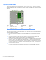
Populating SODIMM sockets ............................................................................................................. 18
Installing SODIMMs ........................................................................................................................... 19
Replacing the battery .......................................................................................................................................... 22
Installing a security lock ...................................................................................................................................... 25
Cable lock .......................................................................................................................................... 25
Padlock .............................................................................................................................................. 25
Appendix A Electrostatic discharge ................................................................................................................. 26
Preventing electrostatic damage ........................................................................................................................ 26
Grounding methods ............................................................................................................................................. 26
v

Appendix B Computer operating guidelines, routine care and shipping preparation ............................................ 27
Computer operating guidelines and routine care ............................................................................................... 27
Shipping preparation ........................................................................................................................................... 28
Index ............................................................................................................................................................. 29
vi

1 Product features
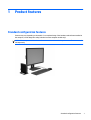
Standard configuration features
Features may vary depending on the model. For a complete listing of the hardware and software installed in
the computer, run the diagnostic utility (included on some computer models only).
NOTE: This computer model can be used in a tower orientation or a desktop orientation. The tower stand is
sold separately.
Standard configuration features 1

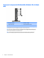
Front panel components (EliteDesk 800, EliteDesk 705, ProDesk
600)
1 Dual-State Power Button 4 USB 3.0 Port - Charging
2 Hard Drive Activity Light 5 Microphone/Headphone Connector
3 USB 3.0 Port 6 Headphone Connector
NOTE: The USB 3.0 Port - Charging also provides current to charge a device such as a Smart Phone. The charging current
is available whenever the power cord is plugged into the system, even when the system is off.
NOTE: When a device is plugged into the Microphone/Headphone Connector, a dialog box will pop up asking if you want
to use the connector for a microphone Line-In device or a headphone. You can reconfigure the connector at any time by
double-clicking the Audio Manager icon in the Windows taskbar.
NOTE: The Power On Light is normally white when the power is on. If it is flashing red, there is a problem with the
computer and it is displaying a diagnostic code. Refer to the Maintenance and Service Guide to interpret the code.
2 Chapter 1 Product features

Front panel components (ProDesk 400)
1 Dual-State Power Button 4 Microphone Connector
2 Hard Drive Activity Light 5 Headphone Connector
3 USB 3.0 Ports
NOTE: The Power On Light is normally white when the power is on. If it is flashing red, there is a problem with the
computer and it is displaying a diagnostic code. Refer to the Maintenance and Service Guide to interpret the code.
Front panel components (ProDesk 400) 3

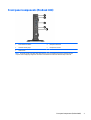
Rear panel components (EliteDesk 800)
1 DisplayPort Monitor Connectors 4 USB 3.0 Ports (blue)
2
VGA Monitor Connector 5 RJ-45 Network Connector
3
Line-Out Connector for powered audio devices
(green)
6 Power Cord Connector
4 Chapter 1 Product features

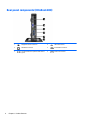
Rear panel components (EliteDesk 705)
1 DisplayPort Monitor Connectors 5 USB 2.0 Ports (black)
2
VGA Monitor Connector 6 RJ-45 Network Connector
3
Line-Out Connector for powered audio devices
(green)
7 Power Cord Connector
4
USB 3.0 Ports (blue)
Rear panel components (EliteDesk 705) 5

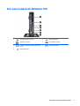
Rear panel components (ProDesk 600)
1 DisplayPort Monitor Connectors 5 USB 3.0 Ports (blue)
2
VGA Monitor Connector 6 RJ-45 Network Connector
3
Line-Out Connector for powered audio devices
(green)
7 Power Cord Connector
4
USB 2.0 Ports (black)
6 Chapter 1 Product features

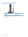
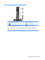
Rear panel components (ProDesk 400)
1 DisplayPort Monitor Connector 4 USB 2.0 Ports (black)
2
VGA Monitor Connector 5 RJ-45 Network Connector
3
USB 2.0 Ports with enhanced power (black) 6 Power Cord Connector
NOTE: The two upper USB ports have additional power capacity to support the Desktop Mini External Expansion Sleeves.
NOTE: The two lower USB ports support wake-from-sleep states if that option is enabled in the Computer Setup (F10)
utility.
Rear panel components (ProDesk 400) 7

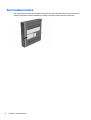
Serial number location
Each computer has a unique serial number and a product ID number that are located on the exterior of the
computer. Keep these numbers available for use when contacting customer service for assistance.
8 Chapter 1 Product features

2 Hardware upgrades
Serviceability features
The computer includes features that make it easy to upgrade and service. No tools are needed for most of
the installation procedures described in this chapter.
Warnings and cautions
Before performing upgrades be sure to carefully read all of the applicable instructions, cautions, and
warnings in this guide.
WARNING! To reduce the risk of personal injury from electrical shock, hot surfaces, or fire:
Disconnect the power cord from the wall outlet and allow the internal system components to cool before
touching.
Do not plug telecommunications or telephone connectors into the network interface controller (NIC)
receptacles.
Do not disable the power cord grounding plug. The grounding plug is an important safety feature.
Plug the power cord in a grounded (earthed) outlet that is easily accessible at all times.
To reduce the risk of serious injury, read the Safety & Comfort Guide. It describes proper workstation, setup,
posture, and health and work habits for computer users, and provides important electrical and mechanical
safety information. This guide is located on the Web at
http://www.hp.com/ergo.
WARNING! Energized and moving parts inside.
Disconnect power to the equipment before removing the enclosure.
Replace and secure the enclosure before re-energizing the equipment.
CAUTION: Static electricity can damage the electrical components of the computer or optional equipment.
Before beginning these procedures, ensure that you are discharged of static electricity by briefly touching a
grounded metal object. See
Electrostatic discharge on page 26 for more information.
When the computer is plugged into an AC power source, voltage is always applied to the system board. You
must disconnect the power cord from the power source before opening the computer to prevent damage to
internal components.
Serviceability features 9

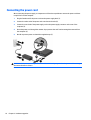
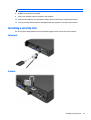
Connecting the power cord
When connecting the power supply, it is important to follow the steps below to ensure the power cord does
not pull free from the computer.
1. Plug the female end of the power cord into the power supply brick (1).
2. Connect the other end of the power cord to an electrical outlet (2).
3. Connect the round end of the power supply cord to the power supply connector on the rear of the
computer (3).
4. Route the power cord through the retainer clip to prevent the cord from becoming disconnected from
the computer (4).
5. Bundle any excess power cord with the supplied strap (5).
CAUTION: Failure to secure the power cable with the retainer clip may result in the power cord becoming
disconnected and loss of data.
10 Chapter 2 Hardware upgrades

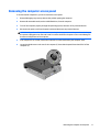
Removing the computer access panel
To access internal components, you must remove the access panel:
1. Remove/disengage any security devices that prohibit opening the computer.
2. Remove all removable media, such as a USB flash drive, from the computer.
3. Turn off the computer properly through the operating system, then turn off any external devices.
4. Disconnect the power cord from the power outlet and disconnect any external devices.
CAUTION: Regardless of the power-on state, voltage is always present on the system board as long as
the system is plugged into an active AC outlet. You must disconnect the power cord to avoid damage to
the internal components of the computer.
5. If the computer is on a stand, remove the computer from the stand and lay the computer down.
6. Loosen the thumbscrew on the rear of the computer (1) then slide the panel forward and lift if off the
computer (2).
Removing the computer access panel 11

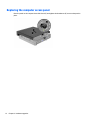
Replacing the computer access panel
Place the panel on the computer then slide it back (1) and tighten the thumbscrew (2) to secure the panel in
place.
12 Chapter 2 Hardware upgrades

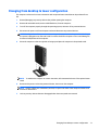
Changing from desktop to tower configuration
The computer can be used in a tower orientation with an optional tower stand that can be purchased from
HP.
1. Remove/disengage any security devices that prohibit opening the computer.
2. Remove all removable media, such as a USB flash drive, from the computer.
3. Turn off the computer properly through the operating system, then turn off any external devices.
4. Disconnect the power cord from the power outlet and disconnect any external devices.
CAUTION: Regardless of the power-on state, voltage is always present on the system board as long as
the system is plugged into an active AC outlet. You must disconnect the power cord to avoid damage to
the internal components of the computer.
5. Orient the computer so that its right side is facing up and place the computer in the optional stand.
NOTE: To stabilize the computer in a tower orientation, HP recommends the use of the optional tower
stand.
6. Reconnect the power cord and any external devices, then turn on the computer.
NOTE: Ensure at least 10.2 centimeters (4 inches) of space on all sides of the computer remains clear
and free of obstructions.
7. Lock any security devices that were disengaged when the access panel was removed.
Changing from desktop to tower configuration 13

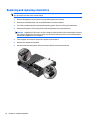
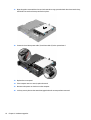
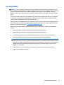
Removing and replacing a hard drive
NOTE: Before you remove the old hard drive, be sure to back up the data from the old hard drive so that
you can transfer the data to the new hard drive.
1. Remove/disengage any security devices that prohibit opening the computer.
2. Remove all removable media, such as a USB flash drive, from the computer.
3. Turn off the computer properly through the operating system, then turn off any external devices.
4. Disconnect the power cord from the power outlet and disconnect any external devices.
CAUTION: Regardless of the power-on state, voltage is always present on the system board as long as
the system is plugged into an active AC outlet. You must disconnect the power cord to avoid damage to
the internal components of the computer.
5. If the computer is on a stand, remove the computer from the stand.
6. Remove the computer access panel.
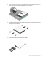
7. Disconnect the hard drive power cable (1) and data cable (2) from the system board.
14 Chapter 2 Hardware upgrades
Page is loading ...
Page is loading ...
Page is loading ...
Page is loading ...
Page is loading ...
Page is loading ...
Page is loading ...
Page is loading ...
Page is loading ...
Page is loading ...
Page is loading ...
Page is loading ...
Page is loading ...
Page is loading ...
Page is loading ...
-
 1
1
-
 2
2
-
 3
3
-
 4
4
-
 5
5
-
 6
6
-
 7
7
-
 8
8
-
 9
9
-
 10
10
-
 11
11
-
 12
12
-
 13
13
-
 14
14
-
 15
15
-
 16
16
-
 17
17
-
 18
18
-
 19
19
-
 20
20
-
 21
21
-
 22
22
-
 23
23
-
 24
24
-
 25
25
-
 26
26
-
 27
27
-
 28
28
-
 29
29
-
 30
30
-
 31
31
-
 32
32
-
 33
33
-
 34
34
-
 35
35


HP Color LaserJet 4650 Printer series Reference guide
- Type
- Reference guide
Ask a question and I''ll find the answer in the document
Finding information in a document is now easier with AI
Related papers
-
HP EliteDesk 800 G2 Small Form Factor PC Reference guide
-
HP EliteDesk 800 35W G3 Desktop Mini PC (ENERGY STAR) Reference guide
-
HP t820 Flexible Thin Client Reference guide
-
HP ProDesk 600 G1 Desktop Mini PC (ENERGY STAR) Maintenance & Service Guide
-
-
HP ProDesk 600 Reference guide
-
HP ProDesk 600 G3 Base Model Desktop Mini PC User guide
-
HP EliteDesk 800 G1 Base Model Ultra-slim PC Reference guide
-
HP ProDesk 400 G1 Desktop Mini PC (ENERGY STAR) User guide
-
HP t620 Flexible Thin Client User guide