Page is loading ...

3
2
1
8
6
7
4
5
DS 14DSL
•
DS 18DSL
Batteridriven borrskruvdragare
Batteridrevet boremaskine
Batteridrevet skrutrekker/boremaskin
Akkutoiminen ruuvainpora
Cordless Driver Drill
Läs igenom bruksanvisningen noga före verktygets användning.
Læs instruktionerne nøje igennem, før maskinen tages i brug.
Les grundig og forstå anvisningene før bruk.
Lue ohjeet huolellisesti ennen käyttöä.
Read through carefully and understand these instructions before use.
804
Code No. C99160484
Printed in China
Bruksanvisning
Brugsanvisning
Bruksanvisning
Käyttöohjeet
Handling Instructions
Hitachi Koki Co., Ltd.
1
J
H
1
6
7
2
8
0
1
9
B
G
D
H
I
C
E
F
D
B
3
1
2
4
5
Representative office in Europe
Hitachi Power Tools Europe GmbH
Siemensring 34, 47877 Willich1, F. R. Germany
Head office in Japan
Hitachi Koki Co., Ltd.
Shinagawa Intercity Tower A, 15-1, Konan 2-chome,
Minato-ku, Tokyo, Japan
30. 4. 2008
K. Kato
Board Director
Svenska
EF-DEKLARATION BETRÄFFANDE LIKFORMIGHET
Vi tillkännagiver med eget ansvar att denna produkt
överensstämmer med standard eller standardiserat
dokument EN60745, EN60335, EN55014 och EN61000 i
enlighet med råddirektiven 2004/108/EF, 2006/95/EF och
98/37/EF.
Denna deklaration gäller för CE-märkningen pà
produkten.
Suomi
EY-ILMOITUS YHDENMUKAISUUDESTA
Yksinomaisella vastuudella vakuutamme, että tämä
tuote vastaa normeja tai normitettuja dokumentteja
EN60745, EN60335, EN55014 ja EN61000 yhteisön
ohjeiden 2004/108/EY, 2006/95/EY ja 98/37/EY
mukaisesti.
Tämä ilmoitus sovelletaan tuotekohtaiseen CE-
merkintään.
English
EC DECLARATION OF CONFORMITY
We declare under our sole responsibility that this
product is in conformity with standards or standardized
documents EN60745, EN60335, EN55014 and EN61000
in accordance with Council Directives 2004/108/EC,
2006/95/EC and 98/37/EC.
This declaration is applicable to the product affixed CE
marking.
Dansk
EF-OVERENSS TEMMELSESERKLÆRING
Vi erlkærer os fuldstændige ansvarlige for, at dette
produkt modsvarer gældende standard eller de
standardiserede dokumenter EN60745, EN60335,
EN55014 og EN61000 i overensstemmelse med EF-
direktiver 2004/108/EF, 2006/95/EF og 98/37/EF.
Denne erklæring qælder produkter, der er mærket med
CE.
Norsk
EF’S ERKLÆRING OM OVERENSSTEMMELSE
Vi erklærer herved at vi påtar oss eneansvaret for at
dette produktet er i overensstermmelse med normer
eller standardiserte dokumenter EN60745, EN60335,
EN55014 og EN61000 i samsvar med Rådsdirektiver
2004/108/EF, 2006/95/EF og 98/37/EF.
Denne erklæringen gjelder produktets påklistrede CE-
merking.
A
A
<BSL1430, BSL1415> <BSL1830>
DS14DSL
3
2
1
8
6
7
4
5
DS 14DSL
•
DS 18DSL
Batteridriven borrskruvdragare
Batteridrevet boremaskine
Batteridrevet skrutrekker/boremaskin
Akkutoiminen ruuvainpora
Cordless Driver Drill
Läs igenom bruksanvisningen noga före verktygets användning.
Læs instruktionerne nøje igennem, før maskinen tages i brug.
Les grundig og forstå anvisningene før bruk.
Lue ohjeet huolellisesti ennen käyttöä.
Read through carefully and understand these instructions before use.
804
Code No. C99160484
Printed in China
Bruksanvisning
Brugsanvisning
Bruksanvisning
Käyttöohjeet
Handling Instructions
Hitachi Koki Co., Ltd.
1
J
H
1
6
7
2
8
0
1
9
B
G
D
H
I
C
E
F
D
B
3
1
2
4
5
Representative office in Europe
Hitachi Power Tools Europe GmbH
Siemensring 34, 47877 Willich1, F. R. Germany
Head office in Japan
Hitachi Koki Co., Ltd.
Shinagawa Intercity Tower A, 15-1, Konan 2-chome,
Minato-ku, Tokyo, Japan
30. 4. 2008
K. Kato
Board Director
Svenska
EF-DEKLARATION BETRÄFFANDE LIKFORMIGHET
Vi tillkännagiver med eget ansvar att denna produkt
överensstämmer med standard eller standardiserat
dokument EN60745, EN60335, EN55014 och EN61000 i
enlighet med råddirektiven 2004/108/EF, 2006/95/EF och
98/37/EF.
Denna deklaration gäller för CE-märkningen pà
produkten.
Suomi
EY-ILMOITUS YHDENMUKAISUUDESTA
Yksinomaisella vastuudella vakuutamme, että tämä
tuote vastaa normeja tai normitettuja dokumentteja
EN60745, EN60335, EN55014 ja EN61000 yhteisön
ohjeiden 2004/108/EY, 2006/95/EY ja 98/37/EY
mukaisesti.
Tämä ilmoitus sovelletaan tuotekohtaiseen CE-
merkintään.
English
EC DECLARATION OF CONFORMITY
We declare under our sole responsibility that this
product is in conformity with standards or standardized
documents EN60745, EN60335, EN55014 and EN61000
in accordance with Council Directives 2004/108/EC,
2006/95/EC and 98/37/EC.
This declaration is applicable to the product affixed CE
marking.
Dansk
EF-OVERENSS TEMMELSESERKLÆRING
Vi erlkærer os fuldstændige ansvarlige for, at dette
produkt modsvarer gældende standard eller de
standardiserede dokumenter EN60745, EN60335,
EN55014 og EN61000 i overensstemmelse med EF-
direktiver 2004/108/EF, 2006/95/EF og 98/37/EF.
Denne erklæring qælder produkter, der er mærket med
CE.
Norsk
EF’S ERKLÆRING OM OVERENSSTEMMELSE
Vi erklærer herved at vi påtar oss eneansvaret for at
dette produktet er i overensstermmelse med normer
eller standardiserte dokumenter EN60745, EN60335,
EN55014 og EN61000 i samsvar med Rådsdirektiver
2004/108/EF, 2006/95/EF og 98/37/EF.
Denne erklæringen gjelder produktets påklistrede CE-
merking.
A
A
<BSL1430, BSL1415> <BSL1830>
DS14DSL
17
18
15
11
12
14
16
13
9 10
48
2 3
K
L
L
M
K
O
N
R
Q
S
T
U
V
V
Y
X
W
3mm
11.5mm
Z
P
Hitachi Power Tools Norway AS
Kjeller Vest 7
Postboks 124, 2007 Kjeller, Norway
Tel: (+47) 6692 6600
Fax: (+47) 6692 6650
URL: http://www.markt.no
Hitachi Power Tools Sweden AB
Rotebergsvagen 2B
SE-192 78 Sollentuna, Sweden
Tel: (+46) 8 598 999 00
Fax: (+46) 8 598 999 40
URL: http://www.markt.se
Hitachi Power Tools Denmark AS
Lillebaeltsvej 90
DK-6715 Esbjerg N, Denmark
Tel: (+45) 75 14 32 00
Fax: (+45) 75 14 36 66
URL: http://www.markt.dk
Hitachi Power Tools Finland OY
Tupalankatu 9
FIN-15680 Lahti, Finland
Tel: (+358) 20 7431 530
Fax: (+358) 20 7431 531
URL: http://www.markt.fi

4
Svenska Dansk Norsk Suomi English
Uppladdningsbart Genopladeligt Oppladbart Ladattava Rechargeable
batteri batteri batteri paristo battery
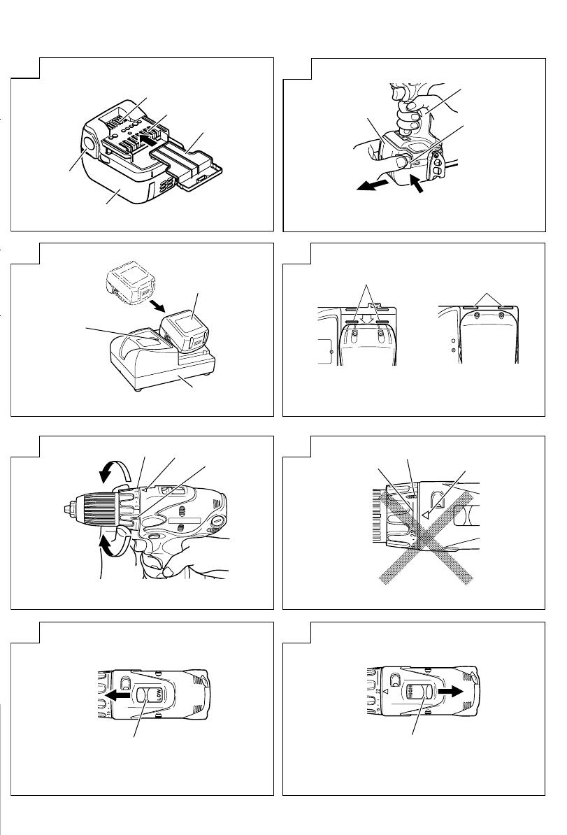
Lås Smæklås Sperrehake Salpa Latch
Batteriskydd Batteridæksel Batterideksel Akun kansi Battery cover
Anslutning Stik Terminal Jakorasia Terminal
Ventilator Blæser Ventilator Tuuletin Ventilator
Tryck Skub Trykk Paina Push
Dra ut Træk ud Dra ut Ota ulos Pull out
Handtag Håndtag Håndtak Kahva Handle
Laddare Opladeapparat Lader Laturi Charger
Indikeringslampa Indikatorlampe for Indikatorlampe for Latausajan Charging time
för laddningstid opladningstid ladetid merkkivalo indicator lamp
Ledning Linje Linje Viiva Line
Borrläge Boremærkning Bormerke Porausmerkki Drill mark
Kopplingsskiva Koblingsskalaen Clutchskive Kytkimen säätöpyörä Clutch dial
Triangelmärke Trekantmærke Trekantmerke Kolmikulmiomerkki Triangle mark
Svag
Svag Svak Kevyt Weak
åtdragningskraft
Stark
Stærk Sterk Vahva Strong
åtdragningskraft
Streck Linje Linje Viiva Line
Hastighetsomkopplare
Omskifterknap Omskifterbryter Liukunäppäin Shift knob
Låg hastighet Lav hastighed Lav hastighet Hidas Low speed
Hög hastighet Høj hastighed Høy hastighet Nopea High speed
Skruv Skrue Skrue Ruuvi Screw
Krok Krog Krok Koukku Hook
Spår Rille Spor Ura Groove
Knapp för Indikatorkontakt for
Indikatorbryter for
Jäljellä olevan
Remaining battery
kvarvarande batteri resterende batteri
gjenværende batterinivå
latauksen merkkikytkin
indicator switch
Indikeringslampa för Indikatorlampe for
Indikatorlampe for
Jäljellä olevan
Remaining battery
kvarvarande batteri resterende batteri
gjenværende batterinivå
latauksen merkkivalo
indicator lamp
Lampknapp Lyskontakt Lysbryter Merkkivalon kytkin Light switch
Chuckhylsa Muffe Muffe Holkki Sleeve
Dra åt Fastgøre Stramme Kiristää Tighten
Lossa Løsne Løsne Irrottaa Loosen
Startomkopplare Aftrækkerkontakt Starbryter Käynnistysliipaisin Trigger switch
Väljarknapp Vælgerknap Velgerknapp Valintapainike Selector button
Lägena
R
(höger)
R
og
L
R
og
L
merker
R
ja
L
merkit
R
and
L
marks
och
L
(väster) afmærknin
Avnötningsgräns Slidgrænse Slitasjegrense Kulutusraja Wear limit
Nagel på kolborste Kulbørstes søm Stift på kullbørste Hiiliharjan kynsi Nail of carbon brush
Utbuktning på Fremspring på Utstikkende del
Hiiliharjan ulkonema
Protrusion of carbon
kolborste kulbørste på kullbørsten brush
Kontaktdel på
Kontaktdel på Kontaktpunkt Harjaputken Contact portion
borstmunstyckets
udvendigt børsterør utfenfor børsterøret ulkokontaktiosa outside brush tube
utsida
1
2
3
4
5
6
7
8
9
0
A
B
C
D
E
F
G
H
I
J
K
L
M
N
O
P
Q
R
S
T
U
V
W
X
Y
Z
5
Symboler
Nedan visas de
symboler som används
för maskinen. Se till att
du förstår vad de
betyder innan verktyget
används.
Symboler
Det følgende viser
symboler, som anvendes
for maskinen. Vær sikker
på, at du forstår deres
betydning, inden du
begynder at bruge
maskinen.
Symboler
Følgende symboler
brukes for maskinen.
Sørg for å forstå
betydningen av disse
symbolene før
maskinen tas i bruk.
Symbolit
Seuraavassa on näytetty
koneessa käytetyt
symbolit. Varmista, että
ymmärrät niiden
merkityksen ennen kuin
aloitat koneen käytön.
Symbols
The following show
symbols used for the
machine. Be sure that
you understand their
meaning before use.
Gäller endast EU-länder
Elektriska verktyg får inte
kastas i hushållssoporna!
Enligt direktivet 2002/96/EG
som avser äldre elektrisk
och elektronisk utrustning
och dess tillämpning enligt
nationell lagstiftning ska
uttjänta elektriska verktyg
sorteras separat och lämnas
till miljövänlig återvinning.
Kun for EU-lande
Elværktøj må ikke
bortskaffes som almindeligt
affald!
I henhold til det europæiske
direktiv 2002/96/EF om
bortskaffelse af elektriske og
elektroniske produkter og
gældende national
lovgivning skal brugt
elværktøj indsamles separat
og bortskaffes på en måde,
der skåner miljøet mest
muligt.
Kun for EU-land
Kast aldri elektroverktøy i
husholdningsavfallet!
I henhold til EU-direktiv
2002/96/EF om kasserte
elektriske og elektroniske
produkter og direktivets
iverksetting i nasjonal rett,
må elektroverktøy som ikke
lenger skal brukes, samles
separat og returneres til et
miljøvennlig
gjenvinningsanlegg.
Koskee vain EU-maita
Älä hävitä sähkötyökalua
tavallisen kotitalousjätteen
mukana!
Vanhoja sähkö- ja
elektroniikkalaitteita
koskevan EU-direktiivin
2002/96/ETY ja sen
maakohtaisten sovellusten
mukaisesti käytetyt
sähkötyökalut on
toimitettava ongelmajätteen
keräyspisteeseen ja
ohjattava
ympäristöystävälliseen
kierrätykseen.
Only for EU countries
Do not dispose of electric
tools together with
household waste material!
In observance of European
Directive 2002/96/EC on
waste electrical and
electronic equipment and its
implementation in
accordance with national
law, electric tools that have
reached the end of their life
must be collected
separately and returned to
an environmentally
compatible recycling
facility.
Läs bruksanvisningen
Læs brugsanvisningen Les instruksjonshåndboken.
Lue käyttöohje. Read instruction manual

English
38
GENERAL POWER TOOL SAFETY WARNINGS
WARNING
Read all safety warnings and all instructions.
Failure to follow the warnings and instructions may result
in electric shock, fire and/or serious injury.
Save all warnings and instructions for future reference.
The term “power tool” in the warnings refers to your
mains-operated (corded) power tool or battery-operated
(cordless) power tool.
1) Work area safety
a) Keep work area clean and well lit.
Cluttered or dark areas invite accidents.
b) Do not operate power tools in explosive
atmospheres, such as in the presence of
flammable liquids, gases or dust.
Power tools create sparks which may ignite the
dust or fumes.
c) Keep children and bystanders away while
operating a power tool.
Distractions can cause you to lose control.
2) Electrical safety
a) Power tool plugs must match the outlet.
Never modify the plug in any way.
Do not use any adapter plugs with earthed
(grounded) power tools.
Unmodified plugs and matching outlets will
reduce risk of electric shock.
b) Avoid body contact with earthed or grounded
surfaces, such as pipes, radiators, ranges and
refrigerators.
There is an increased risk of electric shock if
your body is earthed or grounded.
c) Do not expose power tools to rain or wet
conditions.
Water entering a power tool will increase the
risk of electric shock.
d) Do not abuse the cord. Never use the cord for
carrying, pulling or unplugging the power tool.
Keep cord away from heat, oil, sharp edges or
moving parts.
Damaged or entangled cords increase the risk
of electric shock.
e) When operating a power tool outdoors, use an
extension cord suitable for outdoor use.
Use of a cord suitable for outdoor use reduces
the risk of electric shock.
f) If operating a power tool in a damp location
is unavoidable, use a residual current device
(RCD) protected supply.
Use of an RCD reduces the risk of electric shock.
3) Personal safety
a) Stay alert, watch what you are doing and use
common sense when operating a power tool.
Do not use a power tool while you are tired or
under the influence of drugs, alcohol or medication.
A moment of inattention while operating power
tools may result in serious personal injury.
b) Use personal protective equipment. Always wear
eye protection.
Protective equipment such as dust mask, non-
skid safety shoes, hard hat, or hearing protection
used for appropriate conditions will reduce
personal injuries.
c) Prevent unintentional starting. Ensure the switch
is in the off-position before connecting to power
source and/or battery pack, picking up or
carrying the tool.
Carrying power tools with your finger on the
switch or energising power tools that have the
switch on invites accidents.
d) Remove any adjusting key or wrench before
turning the power tool on.
A wrench or a key left attached to a rotating part
of the power tool may result in personal injury.
e) Do not overreach. Keep proper footing and
balance at all times.
This enables better control of the power tool in
unexpected situations.
f) Dress properly. Do not wear loose clothing or
jewellery. Keep your hair, clothing and gloves
away from moving parts.
Loose clothes, jewellery or long hair can be
caught in moving parts.
g) If devices are provided for the connection of
dust extraction and collection facilities, ensure
these are connected and properly used.
Use of dust collection can reduce dust related hazards.
4) Power tool use and care
a) Do not force the power tool. Use the correct
power tool for your application.
The correct power tool will do the job better and
safer at the rate for which it was designed.
b) Do not use the power tool if the switch does
not turn it on and off.
Any power tool that cannot be controlled with
the switch is dangerous and must be repaired.
c) Disconnect the plug from the power source
and/or the battery pack from the power tool
before making any adjustments, changing
accessories, or storing power tools.
Such preventive safety measures reduce the risk
of starting the power tool accidentally.
d) Store idle power tools out of the reach of children
and do not allow persons unfamiliar with the
power tool or these instructions to operate the
power tool.
Power tools are dangerous in the hands of
untrained users.
e) Maintain power tools. Check for misalignment
or binding of moving parts, breakage of parts
and any other condition that may affect the
power tools operation.
If damaged, have the power tool repaired before
use.
Many accidents are caused by poorly maintained
power tools.
f) Keep cutting tools sharp and clean.
Properly maintained cutting tools with sharp
cutting edges are less likely to bind and are
easier to control.
g) Use the power tool, accessories and tool bits
etc. in accordance with these instructions, taking
into account the working conditions and the
work to be performed.
Use of the power tool for operations different from
those intended could result in a hazardous situation.
English
39
5) Battery tool use and care
a) Recharge only with the charger specified by the
manufacturer.
A charger that is suitable for one type of battery
pack may create a risk of fire when used with
another battery pack.
b) Use power tools only with specifically designated
battery packs.
Use of any other battery packs may create a risk
of injury and fire.
c) When battery pack is not in use, keep it away
from other metal objects like paper clips, coins,
keys, nails, screws, or other small metal objects
that can make a connection from one terminal
to another.
Shorting the battery terminals together may
cause burns or a fire.
d) Under abusive conditions, liquid may be ejected
from the battery; avoid contact. If contact
accidentally occurs, flush with water. If liquid
contacts eyes, additionally seek medical help.
Liquid ejected from the battery may cause
irritation or burns.
6) Service
a) Have your power tool serviced by a qualified repair
person using only identical replacement parts.
This will ensure that the safety of the power tool
is maintained.
PRECAUTION
Keep children and infirm persons away.
When not in use, tools should be stored out of reach of
children and infirm persons.
PRECAUTIONS FOR CORDLESS DRIVER DRILL
1. Always charge the battery at a temperature of 0 –
40°C. A temperature of less than 0°C will result in
over charging which is dangerous. The battery
cannot be charged at a temperature higher than
40°C.
The most suitable temperature for charging is that
of 20 – 25°C.
2. When one charging is completed, leave the charger
for about 15 minutes before the next charging of
battery.
Do not charge more than two batteries
consecutively.
3. Do not allow foreign matter to enter the hole for
connecting the rechargeable battery.
4. Never disassemble the rechargeable battery and
charger.
5. Never short-circuit the rechargeable battery. Short-
circuiting the battery will cause a great electric
current and overheat. It results in burn or damage
to the battery.
6. Do not dispose of the battery in fire.
If the battery is burnt, it may explode.
7. When drilling in wall, floor or ceiling, check for
buried electric power cord, etc.
8. Bring the battery to the shop from which it was
purchased as soon as the post-charging battery life
becomes too short for practical use. Do not dispose
of the exhausted battery.
9. Using an exhausted battery will damage the charger.
10. Do not insert object into the air ventilation slots of
the charger.
Inserting metal objects or inflammables into the
charger air ventilation slots will result in electrical
shock hazard or damaged charger.
11. When mounting a bit into the keyless chuck, tighten
the sleeve adequately. If the sleeve is not tight, the
bit may slip or fall out, causing injury.
12. This product contains a strong permanent magnet
in the motor.
Observe the following precautions regarding
adhering of chips to the tool and the effect of the
permanent magnet on electronic devices.
CAUTION:
Do not place the tool on a workbench or work
area where metal chips are present.
The chips may adhere to the tool, resulting in
injury or malfunction.
If chips have adhered to the tool, do not touch it.
Remove the chips with a brush.
Failure to do so may result in injury.
If you use a pacemaker or other electronic medical
device, do not operate or approach the tool.
Operation of the electronic device may be affected.
Do not use the tool in the vicinity of precision
devices such as cell phones, magnetic cards or
electronic memory media.
Doing so may lead to misoperation, malfunction
or loss of data.
CAUTION ON LITHIUM-ION BATTERY
To extend the lifetime, the lithium-ion battery equips
with the protection function to stop the output.
In the cases of 1 to 3 described below, when using this
product, even if you are pulling the switch, the motor
may stop. This is not the trouble but the result of
protection function.
1. When the battery power remaining runs out, the
motor stops.
In such case, charge it up immediately.
2. If the tool is overloaded, the motor may stop. In
this case, release the switch of tool and eliminate
causes of overloading. After that, you can use it
again.
3. If the battery is overheated under overload work,
the battery power may stop.
In this case, stop using the battery and let the
battery cool. After that, you can use it again.
(BSL1415, BSL1830)
Furthermore, please heed the following warning and
caution.
WARNING
In order to prevent any battery leakage, heat generation,
smoke emission, explosion and ignition beforehand,
please be sure to heed the following precautions.
1. Make sure that swarf and dust do not collect on
the battery.
During work make sure that swarf and dust do not
fall on the battery.

English
40
Make sure that any swarf and dust falling on the
power tool during work do not collect on the battery.
Do not store an unused battery in a location exposed
to swarf and dust.
Before storing a battery, remove any swarf and
dust that may adhere to it and do not store it together
with metal parts (screws, nails, etc.).
2. Do not pierce battery with a sharp object such as a
nail, strike with a hammer, step on, throw or subject
the battery to severe physical shock.
3. Do not use an apparently damaged or deformed
battery.
4. Do not use the battery in reverse polarity.
5. Do not connect directly to an electrical outlets or
car cigarette lighter sockets.
6. Do not use the battery for a purpose other than
those specified.
7. If the battery charging fails to complete even when
a specified recharging time has elapsed,
immediately stop further recharging.
8. Do not put or subject the battery to high
temperatures or high pressure such as into a
microwave oven, dryer, or high pressure container.
9. Keep away from fire immediately when leakage or
foul odor are detected.
10. Do not use in a location where strong static
electricity generates.
11. If there is battery leakage, foul odor, heat generated,
discolored or deformed, or in any way appears
abnormal during use, recharging or storage,
immediately remove it from the equipment or
battery charger, and stop use.
CAUTION
1. If liquid leaking from the battery gets into your
eyes, do not rub your eyes and wash them well
with fresh clean water such as tap water and contact
a doctor immediately.
If left untreated, the liquid may cause eye-problems.
2. If liquid leaks onto your skin or clothes, wash well
with clean water such as tap water immediately.
There is a possibility that this can cause skin irritation.
3. If you find rust, foul odor, overheating, discolor,
deformation, and/or other irregularities when using
the battery for the first time, do not use and return it
to your supplier or vendor.
WARNING
If a conductive foreign matter enters in the terminal of
lithium ion battery, the battery may be shorted, causing
fire. . When storing the lithium ion battery, obey surely
the rules of following contents.
Do not place conductive debris, nail and wires such
as iron wire and copper wire in the storage case.
To prevent shorting from occurring, load the battery
in the tool or insert securely the battery cover for
storing until the ventilator is not seen.
*1 When using the battery BSL1430 and BSL1830.
Weight 1.7 kg 1.5 kg 1.8 kg
SPECIFICATIONS
POWER TOOL
Model DS14DSL DS18DSL
No-load speed (Low/High) 0–400/0–1400 min
–1
Wood
Drilling
(Thickness 18 mm)
36 mm
Metal Steel: 13 mm,
(Thickness 1.6 mm) Aluminum: 13 mm
Machine screw 6 mm
Driving
Wood screw
6.8 mm (diameter) × 50 mm (length) 8 mm (diameter) × 75 mm (length)
(Requires a pilot hole) (Requires a pilot hole)
Rechargeable battery BSL1430: Li-ion 14.4 V BSL1415: Li-ion 14.4 V BSL1830: Li-ion 18 V
(3.0 Ah 8 cells) (1.5 Ah 4 cells) (3.0 Ah 10 cells)
Capacity*
1
CHARGER
Model UC18YRSL
Charging voltage 14.4 V 18 V
Weight 0.6 kg
English
41
STANDARD ACCESSORIES
Standard accessories are subject to change without
notice.
OPTIONAL ACCESSORIES (sold separately)
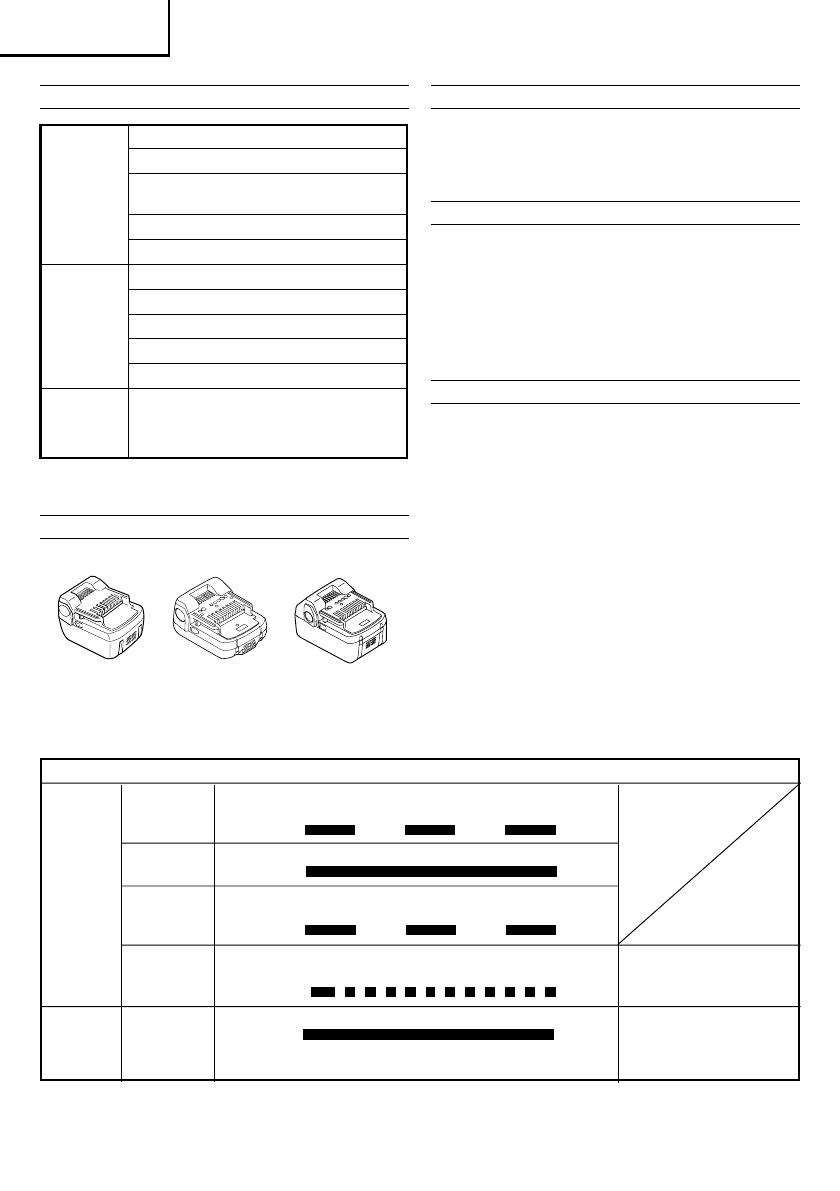
Battery
Optional accessories are subject to change without notice.
APPLICATIONS
Driving and removing of machine screws, wood
screws, tapping screws, etc.
Drilling of various metals
Drilling of various woods
BATTERY REMOVAL/INSTALLATION
1. Battery removal
Hold the handle tightly and push the battery latch to
remove the battery (see Figs. 1 and 2).
CAUTION:
Never short-circuit the battery.
2. Battery installation
Insert the battery while observing its polarities (see
Fig. 2).
CHARGING
Before using the driver drill, charge the battery as follows.
1. Connect the charger’s power cord to a receptacle.
When the power cord is connected, the charger’s
pilot lamp will blink in red. (At 1-second intervals)
2. Insert the battery into the charger.
Firmly insert the battery into the charger until the line
is visible, as shown in Fig. 3, 4.
3. Charging
When inserting a battery in the charger, charging will
commence and the pilot lamp will light continuously
in red.
When the battery becomes fully recharged, the pilot
lamp will blink in red. (At 1-second intervals) (See
Table 1)
(1) Pilot lamp indication
The indications of the pilot lamp will be as shown in
Table 1, according to the condition of the charger or
the rechargeable battery.
Table 1
Indications of the pilot lamp
Lights for 0.5 seconds. Does not light for 0.5
seconds. (off for 0.5 seconds)
Lights continuously
Lights for 0.5 seconds. Does not light for 0.5
seconds. (off for 0.5 seconds)
Lights for 0.1 seconds. Does not light for 0.1
seconds. (off for 0.1 seconds)
Lights continuously
Before
charging
While
charging
Charging
complete
Charging
impossible
Blinks
Lights
Blinks
Flickers
Lights
Malfunction in the
battery or the charger
Battery overheated.
Unable to charge.
(Charging will commence
when battery cools)
The pilot
lamp
lights or
blinks in
red.
The pilot
lamp
lights in
green.
Overheat
standby
DS14DSL
1 Plus driver bit (No.2) .................... 1
(2LSCK)
2 Charger (UC18YRSL) ....................... 1
DS18DSL
3 Battery .............................................. 2
(DS14DSL: BSL1430, DS18DSL: BSL1830)
(2LSCK)
4 Plastic case ....................................... 1
5 Battery cover .................................... 1
DS14DSL
1 Plus driver bit (No.2) .................... 1
2 Charger (UC18YRSL) ....................... 1
3 Battery (BSL1415) ............................ 2
(2LECK)
4 Plastic case ....................................... 1
5 Battery cover .................................... 1
DS14DSL Charger, Battery, Plastic case
(NN)
and Battery cover are not contained.
DS18DSL
(NN)
(BSL1430) (BSL1415)
(BSL1830)
English
42
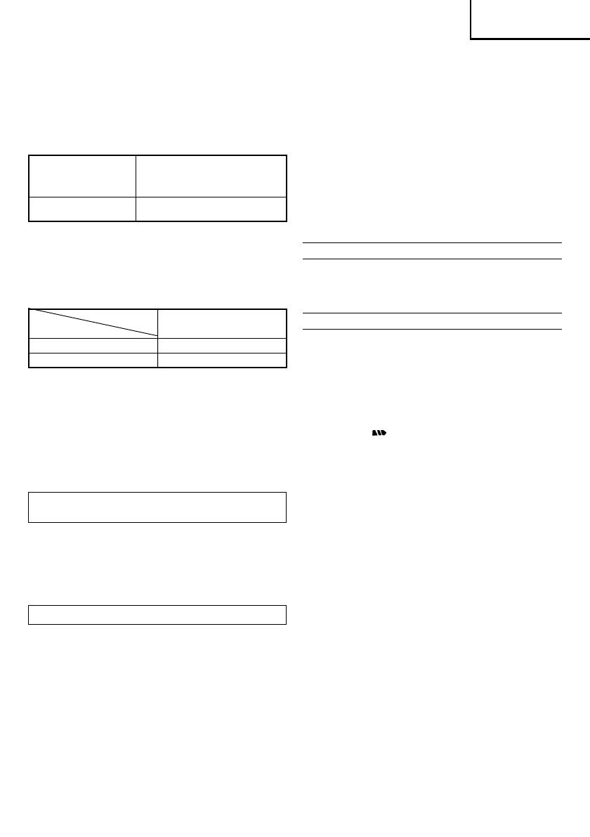
(2) Regarding the temperatures of the rechargeable
battery
The temperatures for rechargeable batteries are as
shown in Table 2, and batteries that have become
hot should be cooled for a while before being
recharged.
Table 2 Recharging ranges of batteries
(3) Regarding recharging time
Depending on the combination of the charger and
batteries, the charging time will become as shown in
Table 3.
Table 3 Charging time (At 20°C)
NOTE:
The charging time may vary according to temperature
and power source voltage.
4. Disconnect the charger’s power cord from the
receptacle.
5. Hold the charger firmly and pull out the battery.
NOTE:
After operation, pull out batteries from the charger
first, and then keep the batteries properly.
Regarding electric discharge in case of new
batteries, etc.
As the internal chemical substance of new batteries
and batteries that have not been used for an extended
period is not activated, the electric discharge might
be low when using them the first and second time.
This is a temporary phenomenon, and normal time
required for recharging will be restored by recharging
the batteries 2 – 3 times.
How to make the batteries perform longer
(1) Recharge the batteries before they become completely
exhausted.
When you feel that the power of the tool becomes
weaker, stop using the tool and recharge its battery.
If you continue to use the tool and exhaust the electric
current, the battery may be damaged and its life will
become shorter.
(2) Avoid recharging at high temperatures.
A rechargeable battery will be hot immediately after
use. If such a battery is recharged immediately after
use, its internal chemical substance will deteriorate,
and the battery life will be shortened. Leave the battery
and recharge it after it has cooled for a while.
CAUTION:
When the battery charger has been continuosly used,
the battery charger will be heated, thus constituting
the cause of the failures. Once the charging has been
completed, give 15 minutes rest until the next charging.
If the battery is recharged when it is warm due to
battery use or exposure to sunlight, the pilot lamp
map light in green.
The battery will not be recharged. In such a case, let
the battery cool before charging.
When the pilot lamp flickers in red (at 0.2-second
intervals), check for and take out any foreign objects
in the charger’s battery installation hole. If there are
no foreign objects, it is probable that the battery or
charger is malfunctioning. Take it to your authorized
Service Center.
PRIOR TO OPERATION
1. Setting up and checking the work environment
Check if the work environment is suitable by following
the precautions.
HOW TO USE
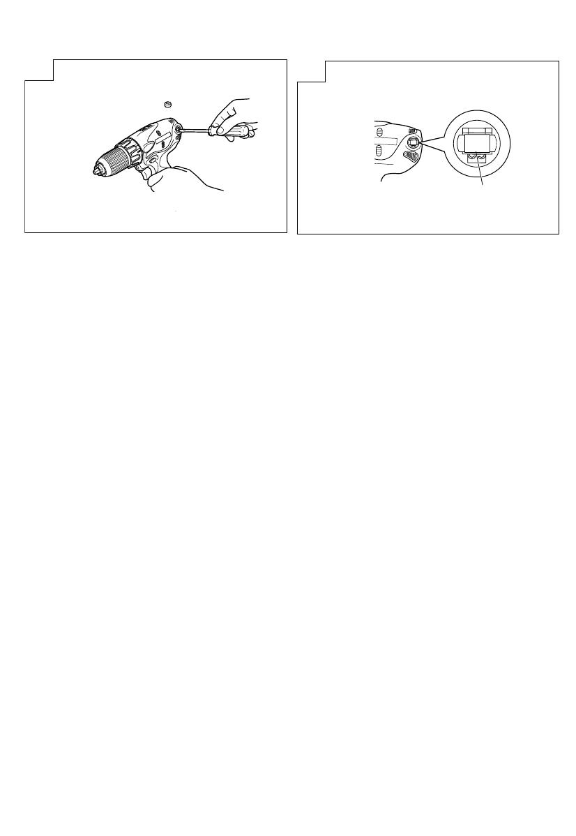
1. Confirm the clutch dial position (see Fig. 5)
The tightening torque of this unit can be adjusted
according to the clutch dial position, at which the
clutch dial is set.
(1) When using this unit as a screwdriver, line up the one
of the numbers “1, 3, 5 ... 22” on the clutch dial, or
the dots, with the triangle mark on the outer body.
(2) When using this unit as a drill, align the clutch dial
drill mark “
” with the triangle mark on the outer
body.
CAUTION:
The clutch dial cannot be set between the numerals
“1, 3, 5 ... 22” or the dots.
Do not use with the clutch dial numeral between
“22” and the line at the middle of the drill mark.
Doing so may cause damage. (See Fig. 6)
2. Tightening torque adjustment
(1) Tightening torque
Tightening torque should correspond in its intensity
to the screw diameter. When too strong torque is
used, the screw head may be broken or be injured.
Be sure to adjust the clutch dial position according to
the screw diameter.
(2) Tightening torque indication
The tightening torque differs depending on the type
of screw and the material being tightened.
The unit indicates the tightening torque with the
numbers “1, 3, 5 ... 22” on the clutch dial , and the
dots. The tightening toque at position “1” is the
weakest and the torque is strongest at the highest
number. (See Fig. 5)
(3) Adjusting the tightening torque
Rotate the clutch dial and line up the numbers “1, 3,
5, ... 22” on the clutch dial, or the dots, with the
triangle mark on the outer body. Adjust the clutch
dial in the weak or the strong torque direction
according to the torque you need.
CAUTION:
The motor rotation may be locked to cease while the
unit is used as drill. While operating the driver drill,
take care not to lock the motor.
Temperatures at
Rechargeable batteries
which the battery
can be recharged
BSL1430, BSL1415,
0°C – 40°C
BSL1830
Charger
UC18YRSL
Battery
BSL1430, BSL1830
Approx.45 min.
BSL1415
Approx.20 min.
English
43
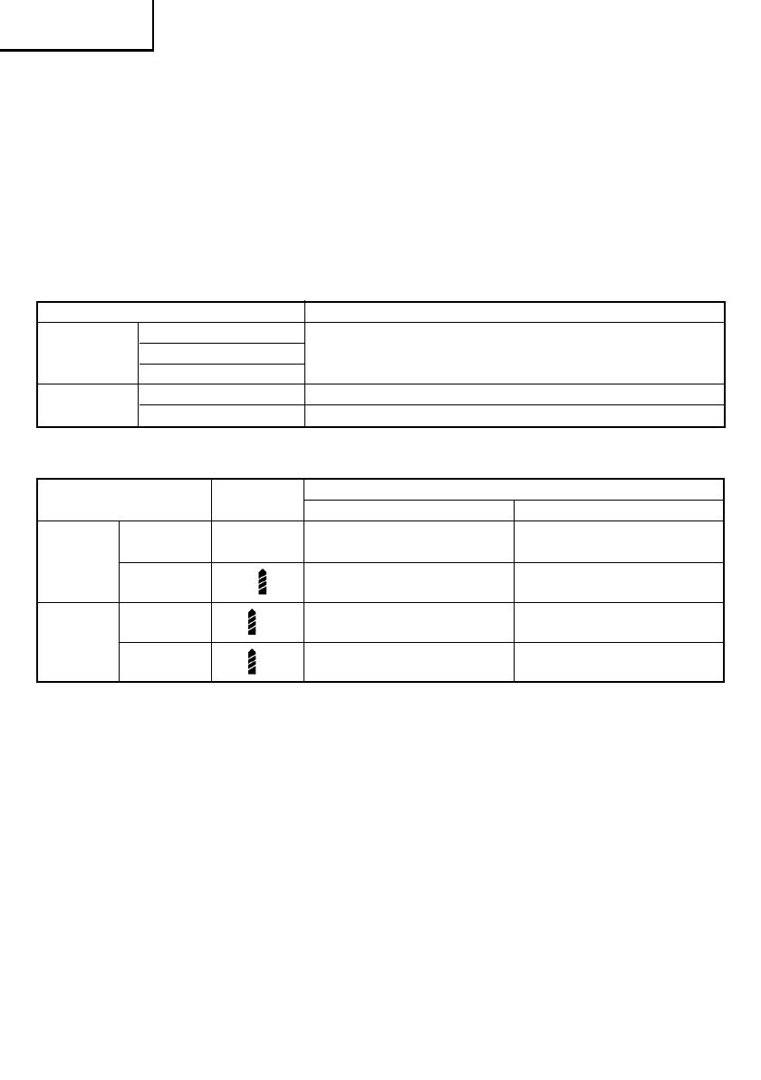
Work Suggestions
Wood
Drilling Steel Use for drilling purpose.
Aluminum
Machine screw Use the bit or socket matching the screw diameter.
Driving
Wood screw Use after drilling a pilot hole.
Table 4
Too long hammering may cause the screw broken
due to excessive tightening.
3. Change rotation speed
Operate the shift knob to change the rotational speed.
Move the shift knob in the direction of the arrow (see
Figs. 7 and 8).
When the shift knob is set to “LOW”, the drill
rotates at a low speed.!»en set to “HIGH”, the drill
rotates at a high speed.
CAUTION:
When changing the rotational speed with the shift
knob, confirm that the switch is off.
Changing the speed while the motor is rotating will
damage the gears.
When setting the shift knob to “HIGH” (high speed)
and the position of the clutch dial is “17” or “22”, it
may happen that the clutch is not engaged and that
the motor is locked. In such a case, please set the
shift knob to “LOW” (low speed).
If the motor is locked, immediately turn the power
off. If the motor is locked for a while, the motor or
battery may be burnt.
Be sure to turn the shift knob.
4. The scope and suggestions for uses
The usable scope for various types of work based on
the mechanical structure of this unit is shown in
Table 4.
Use
Clutch Position
Rotating speed selection (Position of the shift knob)
LOW (Low speed) HIGH (High speed)
Machine
1 – 22
For 4 mm or smaller diameter For 6 mm or smaller
Driving
screw screws. diameter screws.
Wood screw 1 –
For 6.8 mm or smaller nominal For 3.8 mm or smaller
diameter screws. nominal diameter screws.
Wood
For 36 mm or smaller For 18 mm or smaller
Drilling
diameters. diameters.
Metal
For drilling with a metal
–––––––––––––––
working drill bit.
5. How to select tightening torque and rotational speed
Table 5
CAUTION:
The selection examples shown in Table 5 should be
considered as general standard. As different types of
tightening screws and different materials to be
tightened are used in actual works proper adjustments
are naturally necessary.
When using the driver drill with a machine screw at
HIGH (high speed), a screw may damage or a bit may
loose due to the tightning torque is too strong. Use
the driver drill at LOW (low speed) when using a
machine screw.
NOTE:
The use of the battery BSL1430/BSL1415 in a cold
condition (below 0 degree Centigrade) can sometimes
result in the weakened tightening torque and reduced
amount of work. This, however, is a temporary
phenomenon, and returns to normal when the battery
warms up.
The use of the battery BSL1415 is recommended for
light work.
6. Using the hook
The hook is used to hang up the power tool to your
waist belt while working.
CAUTION:
When using the hook, hang up the power tool firmly
not to drop accidentally.
If the power tool is dropped, it may lead to an accident.
When carrying the power tool with hooked to your
waist belt, do not fit any bit to the tip of power tool. If
the sharp bit such as drill is fitted to the power tool
when carrying it with hooked to your waist belt, you
will be injured.
Install securely the hook. Unless the hook is securely
installed, it may cause an injury while using.
(1) Removing the hook.
Remove the screws fixing the hook with Philips screw
driver. (Fig. 9)
(2) Replacing the hook and tightening the screws.
Install securely the hook in the groove of power tool
and tighten the screws to fix the hook firmly. (Fig. 10)
7. About Remaining Battery Indicator
When pressing the remaining battery indicator switch,
the remaining battery indicator lamp lights and the
battery remaining power can be checked. (Fig. 11)

English
44
When releasing your finger from the remaining
battery indicator switch, the remaining battery
indicator lamp goes off. The table 6 shows the state
of remaining battery indicator lamp and the battery
remaining power.
As the remaining battery indicator shows somewhat
differently depending on ambient temperature and
battery characteristics, read it as a reference.
NOTE:
Do not give a strong shock to the switch panel or
break it.
It may lead to a trouble.
To save the battery power consumption, the
remaining battery indicator lamp lights while pressing
the remaining battery indicator switch.
8. How to use the LED light
Every time you press the light switch on the switch
panel, the LED light lights or goes off. (Fig. 12)
To prevent the battery power consumption, turn off
the LED light frequently.
CAUTION:
Do not expose directly your eye to the light by looking
into the light.
If your eye is continuously exposed to the light, your
eye will be hurt.
NOTE:
To prevent the battery power consumption caused
by forgetting to turn off the LED light, the light goes
off automatically in about 15 minutes.
9. Mounting and dismounting of the bit
(1) Mounting the bit
Loosen the sleeve by turning it toward the left (in the
counterclockwise direction as viewed from the front)
to open the clip on the keyless chuck. After inserting
a driver bit, etc., into the keyless drill chuck, and
tighten the sleeve by turning it toward the right (in
the clockwise direction as viewed from the front).
(See Fig. 13)
If the sleeve becomes loose during operation, tighten
it further.
The tightening force becomes stronger when the
sleeve is tightened additionally.
(2) Dismounting the bit
Loosen the sleeve by turning it toward the left (in the
counterclockwise direction as viewed from the front),
and then take out the bit ect. (See Fig. 13)
NOTE:
If the sleeve is tightened in a state where the clip of
the keyless chuck is opened to a maximum limit, a
click noise may occur. This is the noise that occurs
when the loosening of the keyless chuck is prevented
and is not a malfunction.
CAUTION:
When it is no longer possible to loosen the sleeve,
use a vise or similar instrument to secure the bit. Set
the clutch mode between 1 and 11 and then turn the
sleeve to the loose side (left side) while operating the
clutch. It should be easy now to loosen the sleeve.
10. Automatic spindle-lock mechanism
This unit has automatic spindle-lock mechanism for
quick bit changes.
11. Confirm that the battery is mounted correctly
12. Check the rotational direction
The bit rotates clockwise (viewed from the rear side)
by pushing the R-side of the selector button.
The L-side of the selector button is pushed to turn the
bit counterclockwise. (See Fig. 14) (The
L
and
R
marks are provided on the selector button.)
13. Switch operation
When the trigger switch is depressed, the tool rotates.
When the trigger is released, the tool stops.
The rotational speed of the drill can be controlled by
varying the amount that the trigger switch is pulled.
Speed is low when the trigger switch is pulled slightly
and increases as the trigger switch is pulled more.
NOTE:
A buzzing noise is produced when the motor is about
to rotate; This is only a noise, not a machine failure.
MAINTENANCE AND INSPECTION
1. Inspecting the tool
Since use of as dull tool will degrade efficiency and
cause possible motor malfunction, sharpen or replace
the tool as soon as abrasion is noted.
2. Inspecting the mounting screws
Regularly inspect all mounting screws and ensure
that they are properly tightened. Should any of the
screws be loose, retighten them immediately. Failure
to do so could result in serious hazard.
3. Maintenance of the motor
The motor unit winding is the very “heart” of the
power tool.
Exercise due care to ensure the winding does not
become damaged and/or wet with oil or water.
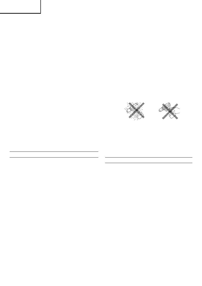
4. Inspecting the carbon brushes (Fig. 15)
The motor employs carbon brushes which are
consumable parts. Since and excessively worn carbon
brush can result in motor trouble, replace the carbon
brush with new ones when it becomes worn to or
near the “wear limit”. In addition, always keep carbon
brushes clean and ensure that they slide freely whthin
the brush holders.
NOTE:
When replacing the carbon brush with a new one, be
sure to use the Hitachi Carbon Brush Code No. 999054.
5. Replacing carbon brushes
Take out the carbon brush by first removing the
brush cap and then hooking the protrusion of the
carbon brush with a flat head screw driver, etc., as
shown in Fig. 17.
When installing the carbon brush, choose the direction
so that the nail of the carbon brush agrees with the
contact portion outside the brush tube. Then push it
in with a finger as illustrated in Fig. 18. Lastly, install
the brush cap.
State
of
Battery Remaining Power
lamp
The battery remaining power is enough.
The battery remaining power is a half.
The battery remaining power is nearly
empty.
Re-charge the battery soonest possible.
Table 6

English
45
CAUTION:
Be absolutely sure to insert the nail of the carbon
brush into the contact portion outside the brush tube.
(You can insert whichever one of the two nails
provided).
Caution must be exercised since any error in this
operation can result in the deformed nail of the carbon
brush and may cause motor trouble at an early stage.
6. Cleaning on the outside
When the driver drill is stained, wipe with a soft dry
cloth or a cloth moistened with soapy water. Do not
use chloric solvents, gasoline or paint thinner, for
they melt plastics.
7. Storage
Store the driver drill in a place in which the tempera
ture is less than 40°C and out of reach of children.
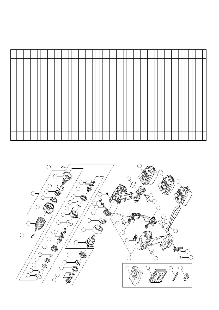
8. Service parts list
CAUTION:
Repair, modification and inspection of Hitachi Power
Tools must be carried out by a Hitachi Authorized
Service Center.
This Parts List will be helpful if presented with the
tool to the Hitachi Authorized Service Center when
requesting repair or other maintenance.
In the operation and maintenance of power tools, the
safety regulations and standards prescribed in each
country must be observed.
MODIFICATIONS:
Hitachi Power Tools are constantly being improved
and modified to incorporate the latest technological
advancements.
Accordingly, some parts may be changed without
prior notice.
NOTE:
Due to HITACHI’s continuing program of research and
development, the specifications herein are subject to
change without prior notice.
Information concerning airborne noise and vibration
The measured values were determined according to
EN60745 and declared in accordance with ISO 4871.
Measured A-weighted sound power level: 98 dB (A)
Measured A-weighted sound pressure level: 87 dB (A)
Uncertainty Kp
A: 3 dB (A).
Wear ear protection.
Vibration total values (triax vector sum) determined
according to EN60745.
Drilling:
Vibration emission value
ah, D = 4.5 m/s
2
Uncertainty K = 1.5 m/s
2
WARNING
The vibration emission value during actual use of the
power tool can differ from the declared value
depending on the ways in which the tool is used.
To identify the safety measures to protect the operator
that are based on an estimation of exposure in the
actual conditions of use (taking account of all parts of
the operating cycle such as the times when the tool is
switched off and when it is running idle in addition to
the trigger time).
46
ITEM
PART NAME Q’TY
NO.
1 SPECIAL SCREW (LEFT HAND) M6X23 1
2 DRILL CHUCK 13VLRG-N (W/O CHUCK WRENCH) 1
3 GEAR BOX ASS’Y 1
4 CLUTCH DIAL 1
5 NUT 1
6 SPRING 1
7 THRUST PLATE 1
8 FRONT CASE 1
9 CLICK SPRING 1
10 ROLLER 6
11 STEEL BALL D5 6
12 WASHER (B) 1
13 LOCK RING 1
14 ROLLER 4
15 RING GEAR 1
16 CARRIER 1
17 PLANET GEAR (C) SET 3
18 PLATE (B) 1
19 REAR ÅCASE 1
20 SCREW SET D3X12 4
21 SHIFT ARM 1
22 SLIDE RING GEAR 1
23 PINION (C) 1
24 PLANET GEAR (B) SET 4
25 PINION (B) 1
26 PLANET GEAR (A) SET 4
27 FIRST RING GEAR 1
28 PLATE (A) 1
29 MOTOR SPACER 1
30 ARMATURE AND PINION SET 1
31 MAGNET 1
32 DUST GUARD 1
33 BRUSH BLOCK 1
34 CARBON BRUSH 5X6X11.5 2
35 BRUSH CAP 2
36 TAPPING SCREW (W/FLANGE) D3X16 8
37 NAME PLATE 1
38 HOUSING SET 1
39 SHIFT KNOB 1
40 DC-SPEED CONTROL SWITCH 1
41 PUSHING BUTTON 1
42 HITACHI LABEL 1
43 M4 TRUSS HD. SCREW(BLACK) 1
44 HOOK (A) 1
45 STRAP (BLACK) 1
46 LOCK NUT M4 (BLACK) 2
47 PACKING 2
48 CONTROLLER TERMINAL 1
49-1 BATTERY (BSL1430) 2
49-2 BATTERY (BSL1415) 1
49-3 BATTERY (BSL1830) 1
501 CHARGER (MODEL UC18YRSL) 1
502 CASE 1
503 + DRIVER BIT NO.2 65L 1
504 BATTERY COVER 1
14
47
46
502
1
2
4
5
6
7
8
9
10
11
13
15
16
17
18
19
20
21
22
23
24
25
26
27
28
29
30
31
32
33
34
35
36
37
42
38
39
40
41
45
501
503
48
46
47
44
43
3
12
504
49
-3
49
-2
49
-1

17
18
15
11
12
14
16
13
9 10
48
2 3
K
L
L
M
K
O
N
R
Q
S
T
U
V
V
Y
X
W
3mm
11.5mm
Z
P
Hitachi Power Tools Norway AS
Kjeller Vest 7
Postboks 124, 2007 Kjeller, Norway
Tel: (+47) 6692 6600
Fax: (+47) 6692 6650
URL: http://www.markt.no
Hitachi Power Tools Sweden AB
Rotebergsvagen 2B
SE-192 78 Sollentuna, Sweden
Tel: (+46) 8 598 999 00
Fax: (+46) 8 598 999 40
URL: http://www.markt.se
Hitachi Power Tools Denmark AS
Lillebaeltsvej 90
DK-6715 Esbjerg N, Denmark
Tel: (+45) 75 14 32 00
Fax: (+45) 75 14 36 66
URL: http://www.markt.dk
Hitachi Power Tools Finland OY
Tupalankatu 9
FIN-15680 Lahti, Finland
Tel: (+358) 20 7431 530
Fax: (+358) 20 7431 531
URL: http://www.markt.fi

3
2
1
8
6
7
4
5
DS 14DSL
•
DS 18DSL
Batteridriven borrskruvdragare
Batteridrevet boremaskine
Batteridrevet skrutrekker/boremaskin
Akkutoiminen ruuvainpora
Cordless Driver Drill
Läs igenom bruksanvisningen noga före verktygets användning.
Læs instruktionerne nøje igennem, før maskinen tages i brug.
Les grundig og forstå anvisningene før bruk.
Lue ohjeet huolellisesti ennen käyttöä.
Read through carefully and understand these instructions before use.
804
Code No. C99160484
Printed in China
Bruksanvisning
Brugsanvisning
Bruksanvisning
Käyttöohjeet
Handling Instructions
Hitachi Koki Co., Ltd.
1
J
H
1
6
7
2
8
0
1
9
B
G
D
H
I
C
E
F
D
B
3
1
2
4
5
Representative office in Europe
Hitachi Power Tools Europe GmbH
Siemensring 34, 47877 Willich1, F. R. Germany
Head office in Japan
Hitachi Koki Co., Ltd.
Shinagawa Intercity Tower A, 15-1, Konan 2-chome,
Minato-ku, Tokyo, Japan
30. 4. 2008
K. Kato
Board Director
Svenska
EF-DEKLARATION BETRÄFFANDE LIKFORMIGHET
Vi tillkännagiver med eget ansvar att denna produkt
överensstämmer med standard eller standardiserat
dokument EN60745, EN60335, EN55014 och EN61000 i
enlighet med råddirektiven 2004/108/EF, 2006/95/EF och
98/37/EF.
Denna deklaration gäller för CE-märkningen pà
produkten.
Suomi
EY-ILMOITUS YHDENMUKAISUUDESTA
Yksinomaisella vastuudella vakuutamme, että tämä
tuote vastaa normeja tai normitettuja dokumentteja
EN60745, EN60335, EN55014 ja EN61000 yhteisön
ohjeiden 2004/108/EY, 2006/95/EY ja 98/37/EY
mukaisesti.
Tämä ilmoitus sovelletaan tuotekohtaiseen CE-
merkintään.
English
EC DECLARATION OF CONFORMITY
We declare under our sole responsibility that this
product is in conformity with standards or standardized
documents EN60745, EN60335, EN55014 and EN61000
in accordance with Council Directives 2004/108/EC,
2006/95/EC and 98/37/EC.
This declaration is applicable to the product affixed CE
marking.
Dansk
EF-OVERENSS TEMMELSESERKLÆRING
Vi erlkærer os fuldstændige ansvarlige for, at dette
produkt modsvarer gældende standard eller de
standardiserede dokumenter EN60745, EN60335,
EN55014 og EN61000 i overensstemmelse med EF-
direktiver 2004/108/EF, 2006/95/EF og 98/37/EF.
Denne erklæring qælder produkter, der er mærket med
CE.
Norsk
EF’S ERKLÆRING OM OVERENSSTEMMELSE
Vi erklærer herved at vi påtar oss eneansvaret for at
dette produktet er i overensstermmelse med normer
eller standardiserte dokumenter EN60745, EN60335,
EN55014 og EN61000 i samsvar med Rådsdirektiver
2004/108/EF, 2006/95/EF og 98/37/EF.
Denne erklæringen gjelder produktets påklistrede CE-
merking.
A
A
<BSL1430, BSL1415> <BSL1830>
DS14DSL
/