Page is loading ...
omega.com
e-mail: [email protected]
For latest product manuals:
omegamanual.info
Shop online at
User’s Guide
OMB-DAQ-3000 Series
1-MHz, 16-Bit USB Data Acquisition Modules
OMB-1136-0901 rev 1.1

Servicing North America:
U.S.A.: One Omega Drive, P.O. Box 4047
ISO 9001 Certified Stamford, CT 06907-0047
TEL: (203) 359-1660 FAX: (203) 359-7700
e-mail: [email protected]
Canada: 976 Bergar
Laval (Quebec) H7L 5A1, Canada
TEL: (514) 856-6928 FAX: (514) 856-6886
e-mail: [email protected]
For immediate technical or application assistance:
U.S.A. and Canada: Sales Service: 1-800-826-6342 / 1-800-TC-OMEGA
®
Customer Service: 1-800-622-2378 / 1-800-622-BEST
®
Engineering Service: 1-800-872-9436 / 1-800-USA-WHEN
®
Mexico: En Espan˜ol: (001) 203-359-7803 e-mail: [email protected]
FAX: (001) 203-359-7807 [email protected]
Servicing Europe:
Benelux: Postbus 8034, 1180 LA Amstelveen, The Netherlands
TEL: +31 (0)20 3472121 FAX: +31 (0)20 6434643
Toll Free in Benelux: 0800 0993344
e-mail: [email protected]
Czech Republic: Frystatska 184, 733 01 Karviná, Czech Republic
TEL: +420 (0)59 6311899 FAX: +420 (0)59 6311114
Toll Free: 0800-1-66342 e-mail: [email protected]
France: 11, rue Jacques Cartier, 78280 Guyancourt, France
TEL: +33 (0)1 61 37 2900 FAX: +33 (0)1 30 57 5427
Toll Free in France: 0800 466 342
e-mail: [email protected]
Germany/Austria: Daimlerstrasse 26, D-75392 Deckenpfronn, Germany
TEL: +49 (0)7056 9398-0 FAX: +49 (0)7056 9398-29
Toll Free in Germany: 0800 639 7678
e-mail: [email protected]
United Kingdom: One Omega Drive, River Bend Technology Centre
ISO 9002 Certified Northbank, Irlam, Manchester
M44 5BD United Kingdom
TEL: +44 (0)161 777 6611 FAX: +44 (0)161 777 6622
Toll Free in United Kingdom: 0800-488-488
e-mail: [email protected]
OMEGAnet
®
Online Service Internet e-mail
omega.com [email protected]
It is the policy of OMEGA Engineering, Inc. to comply with all worldwide safety and EMC/EMI
regulations that apply. OMEGA is constantly pursuing certification of its products to the European New
Approach Directives. OMEGA will add the CE mark to every appropriate device upon certification.
The information contained in this document is believed to be correct, but OMEGA accepts no liability for any
errors it contains, and reserves the right to alter specifications without notice.
WARNING: These products are not designed for use in, and should not be used for, human applications.

Warnings, Cautions, Notes, and Tips
Refer all service to qualified personnel. This symbol warns of possible personal injury or equipment damage under
noted conditions. Follow all safety standards of professional practice and the recommendations in this manual. Using
this equipment in ways other than described in this manual can present serious safety hazards or cause equipment
damage.
This warning symbol is used in this manual or on the equipment to warn of possible injury or death from electrical
shock under noted conditions.
This ESD caution symbol urges proper handling of equipment or components sensitive to damage from electrostatic
discharge. Proper handling guidelines include the use of grounded anti-static mats and wrist straps, ESD-protective
bags and cartons, and related procedures.
This symbol indicates the message is important, but is not of a Warning or Caution category. These notes can be of
great benefit to the user, and should be read.
In this manual, the book symbol always precedes the words “Reference Note.” This type of note identifies the location
of additional information that may prove helpful. References may be made to other chapters or other documentation.
Tips provide advice that may save time during a procedure, or help to clarify an issue. Tips may include additional
reference.
Specifications and Calibration
Specifications are subject to change without notice. Significant changes will be addressed in an addendum or revision to
the manual. As applicable, we calibrate our hardware to published specifications. Periodic hardware calibration is not
covered under the warranty and must be performed by qualified personnel as specified in this manual. Improper
calibration procedures may void the warranty.
iii

iv
Your order was carefully inspected prior to shipment. When you receive your order, carefully
unpack all items from the shipping carton and check for physical signs of damage that may have
occurred during shipment. Promptly report any damage to the shipping agent and your sales
representative. Retain all shipping materials in case the unit needs returned to the factory.
CAUTION
Using this equipment in ways other than described in this manual can cause
personal injury or equipment damage. Before setting up and using your
equipment, you should read all documentation that covers your system.
Pay special attention to Warnings and Cautions.
Note:
During software installation, Adobe
®
PDF versions of user manuals will automatically
install onto your hard drive as a part of product support. The default location is in the
Programs group, which can be accessed from the Windows Desktop. Initial
navigation is as follows:
Start [Desktop “Start” pull-down menu]
⇒ Programs
⇒ Omega DaqX Software
You can also access the PDF documents directly from the data acquisition CD by using
the <View PDFs> button located on the opening screen.
Refer to the PDF documentation for details regarding both hardware and software.
A copy of the Adobe Acrobat Reader
®
is included on your CD. The Reader provides
a means of reading and printing the PDF documents. Note that hardcopy versions of
the manuals can be ordered from the factory.

OMB-DAQ-3000 Series User’s Manual 888494 v
Table of Contents
OMB-DAQ-3000 Series, Installation Guide (p/n OMB-1136-0940; M4260/1205)
1 – Device Overviews
Block Diagrams ….. 1-1
Connections …… 1-2
Theory of Operation…… 1-3
Software …… 1-15
2 – Connections and Pinouts
Overview …… 2-1
Pinout for OMB-DAQ-3000 Series Modules …… 2-2
OMB-PDQ30 Analog Expansion Option …… 2-3
Connecting for Single-Ended or Differential …… 2-5
3 – CE-Compliance
Overview …… 3-1
CE Standards and Directives …… 3-1
Safety Conditions …… 3-2
Emissions/Immunity Conditions …… 3-2
4 – Calibration
5 – Counter Input Modes
Tips for Making High-Speed Counter Measurements ( > 1 MHz ) …… 5-1
Debounce Module …… 5-1
Terms Applicable to Counter Modes…….5-5
Counter Options …… 5-5
Counter/Totalize Mode …… 5-6
Period Mode …… 5-8
Pulsewidth Mode …… 5-11
Timing Mode …… 5-13
Encoder Mode …… 5-15

vi 888494 OMB-DAQ-3000 Series User’s Manual
6 – Setpoint Configuration for Output Control
Overview …… 6-1
Detecting Input Values …… 6-3
Controlling Analog, Digital, and Timer Outputs …… 6-4
P2C, DAC, or Timer Update Latency …… 6-6
More Examples of Control Outputs …… 6-7
Detection on an Analog Input, DAC and P2C Updates …… 6-7
Detection on an Analog Input, Timer Output Updates …… 6-8
Using the Hysteresis Function …… 6-8
Using Multiple Inputs to Control One DAC Output …… 6-10
The Setpoint Status Register …… 6-11
7 – Specifications – OMB-DAQ-3000 Series and OMB-PDQ30
Appendix A: Signal Modes and System Noise
Signal Modes …… A-1
Connecting Thermocouples to Screw-Terminal Blocks …… A-2
Shielding …… A-3
TC Common Mode …… A-3
Cold Junction Compensation Techniques …… A-4
System Noise …… A-5
Averaging …… A-5
Analog Filtering …… A-5
Input and Source Impedance …… A-5
Crosstalk …… A-6
Oversampling and Line Cycle Rejection …… A-6
Glossary

OMB-DAQ-3000 Series Installation Guide
988293 IG-3
OMB-DAQ-3000 Series Installation Guide
Contents
(1) Install Software …… page IG-2
(2) Connect Signal Lines and Hardware ….. page IG-2
(3) Start DaqView ….. page IG-6
(4) Configure the System ….. page IG-6
(5) Collect Data ….. page IG-7
Customer Assistance ….. page IG-8
Reference Note:
After you have completed the installation you should refer to the electronic documents that
were automatically installed onto your hard drive as a part of product support. The default
location is in the Programs group, which can be accessed from the Windows Desktop.
You should keep your OMB-DAQ-3000 Series device model and serial number, as well as any
authorization codes (if applicable) with this document. Space is provided below for recording up to 4
model numbers. Serial numbers and module model (e.g., /3000, /3005) are clearly visible on the units.
Model
3000, 3001,
3005
Serial Number User Notes
Module 1
Module 2
Module 3
Module 4
CAUTION
Take ESD precautions (packaging, proper handling, grounded wrist strap, etc.)
Use care to avoid touching onboard components. Keep the modules clear of foreign
elements such as oils, water, and industrial particulate.
Reference Note: Adobe PDF versions of user manuals will
automatically install onto your hard drive as a part of
product support.** The default location is in the Programs
group, which can be accessed from the Windows Desktop.
Refer to the PDF documentation for details regarding both
hardware and software. Note that hardcopy versions of the
manuals can be ordered from the factory.
** Manuals can also be read directly from the data
acquisition CD via the View PDFs option on the
splash screen or from our web site.
Minimum System
Requirements
Pentium
®
P3 Processor, 500 MHz
Windows Operating System
RAM: 128 Mbytes
Available USB Port*
*USB2.0 recommended

IG-4
988293 OMB-DAQ-3000 Series Installation Guide
(1) Install Software
IMPORTANT: Software must be installed before installing hardware.
(a) Place the Data Acquisition CD into the CD-ROM drive. Wait for PC to auto-run the CD. This may
take a few moments, depending on your PC. If the CD does not auto-run, use the Desktop’s
Start/Run/Browse feature and run the Setup.exe file.
fter the intro-screen appears, follow the screen prompt(b) A
(c) After successful installation turn off the computer and proce
s.
ed with the following section,
onnect Signal Lines and Hardware.
(2) Connect Sig
C
nal Lines and Hardware
CAUTION
The discharge of static electric some electronic components.
Semiconductor devices are especially susceptible to ESD damage. You should always
circuit
ity can damage
handle components carefully, and you should never touch connector pins or
components unless you are following ESD guidelines in an appropriate ESD controlled
area. Such guidelines include the use of properly grounded mats and wrist straps,
ESD bags and cartons, and related procedures.
(a) Connect signal lines to the removable screw-terminal blocks.
ethod. In the following figure
voltage source V1 is connected to Channel 0 and to analog common; and voltage source V2 is
Single-Ended (V1 and V2) and Differential (V3) Connections to Analog Input Channels
he figure shows vol
ine from the thermocouple is shown connected to Channel 1 HI; and the LO (negative) side is
Voltage signals can be connected using the Single-Ended m
connected to Channel 8 and the same analog common connection.
tage V3 resulting from a thermocouple. In this case Differential mode is being used. T
The HI (+) l
connected to Channel 1 LO. Notice that Channel 1 LO is the same screw terminal connection that would
be used for CH 9 Single-Ended.
In OMB-DAQ-3000 Series and OMB-PDQ30 applications, thermocouples should only be
connected in differential mode. Connectin
g thermocouples in single-ended mode can
cause noise and false readings. Appendix A of the user’s manual includes additional
information.
OMB-DAQ-3000 Series Installation Guide
988293 IG-5
Differential connection is made as follows:
1. The red thermocouple wire connects to the channel’s Low (L) connector.
2. The other color wire connects to the channel’s High (H) connector.
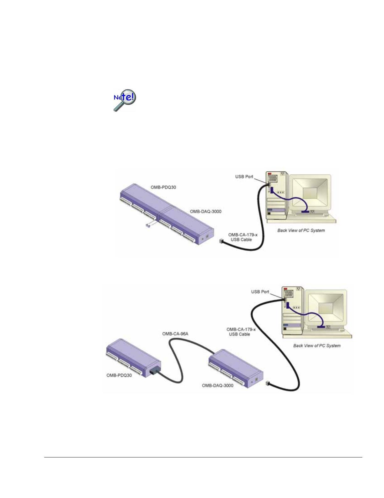
(b) Add the O
MB-PDQ30 Expansion Option, if applicable.
OMB-PDQ30 is not to be connected to a live device. Unplug the USB cable from
-PDQ30.
OMB-PDQ used to add an additional 48 SE
(or 24 DE) analog inputs.
re. When connected directly, i.e., DB25 to DB25, two small clips
the host PC prior to connecting the OMB
30 is an optional analog expansion module that can be
OMB-DAQ-3000 Series modules can connect to an OMB-PDQ30, directly via mating DB25
connectors as indicated in the following figure; or indirectly via an OMB-CA-96 cable, as
indicated in the second figu
(included) are used to hold the modules together.
Direct Connection of OMB-DAQ-3000 and OMB-PDQ30
* Do not connect the OMB-CA-179-x USB cable until step 2d.
Connection of OMB-DAQ-3000 and OMB-PDQ30 via an OMB-CA-96 Expansion Cable
* Do not connect the OMB-CA-179-x USB cable until step 2d.
Note: In the (1, 3, or 5 meters).
figures, the “x” after “OMB-CA-179-” indicates the cable length
IG-6
988293 OMB-DAQ-3000 Series Installation Guide
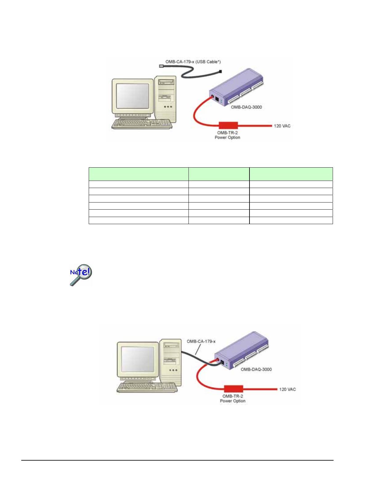
(c) If using an optional OMB-TR-2 power option, connect the OMB-TR-2 to the OMB-DAQ-3000
external power connector; then plug the OMB-TR-2 into a standard 120 VAC outlet.
*Do not connect the OMB-CA-179-x USB cable until step 2d.
Power Cons
1
umption
Model Power Consumption
(Typical)
2
OMB-TR-2 Power Adapter
2
OMB-DAQ-3000 2500 mW Recommended
OMB-DAQ-3001 3000 mW Required
OMB-DAQ-3005 2000 mW Optional
OMB-DAQ-3000 & OMB-PDQ30 2900 mW Required
OMB-DAQ-3001 & OMB-PDQ30 3400 mW Required
OMB-DAQ-3005 & OMB-PDQ30 2400 mW Recommended
1
is for a single OM 000 Ser , or for a single device
expansion modu
2
.
The power consumption listed B-DAQ-3 ies device
connected to an OMB-PDQ30 le.
A power adapter (OMB-TR-2) will be required if the USB port cannot supply adequate power
USB2 ports are, by USB2 standards, required to supply 2500 mW (nominal at 5V, 500 mA).
If using an OMB-TR-2, be sure to supply power from it to the OMB-DAQ-3000 before
connecting the USB cable to the computer. This allows OMB-DAQ-3000 to inform t
he
(d) Use a O -DAQ-3000 Series device to a USB port
on the computer. Note that use of a PC with a USB2.0 port is recommended. A USB1.1 port will
host computer (upon connection of the USB cable) that the unit requires minimal power from
the computer’s USB port.
MB-CA-179-x USB cable to connect the OMBn
work, but will result in lower performance.
Follow the screen prompts as directed. (e)
LEDs: OMB-DAQ-3000 Series modules have 2 LEDs located just right of their USB2 connector.
The LEDs function as follows:
OMB-DAQ-3000 Series Installation Guide
988293 IG-7
D:
. If there is insufficient power the LED will go off and an
Active LED: T AQ-
that the Active LED will be on solid during a
Power LE The “Power” LED blinks during device detection and initialization; then remains on solid as
long as the module has power
OMB-TR-2 power adapter will be needed.
his LED is on whenever active USB communication is taking place between the OMB-D
3000 Series module and the host PC. Note
data acquisition.
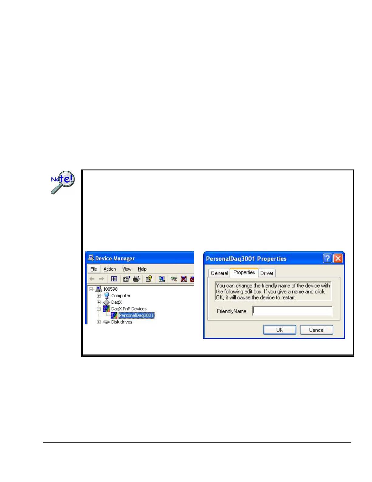
If you need to find the name of your device, for example, if you are writing a custom program for multiple
devices, navigate from the Windows Desktop to the Device Manager. The navigation path is:
P Devices
You can change the name of the device by doing a right-click on the device name to open its properties
he
StartÖSettingsÖControl PanelÖSystemÖHardware(Tab) ÖDevice ManagerÖDaqx Pn
You will see the device listed in the format of PersonalDaq3000 (see first figure, below).
dialog box, then clicking on the Properties tab (see second figure). You can then change t
“FriendlyName” of the device.
Locating DaqXPnP Devices Properties Dialog Box
IG-8
988293 OMB-DAQ-3000 Series Installation Guide
(3) Start DaqView
From Windows, open DaqView by double clicking on its icon, or use the Windows Desktop Start menu to
access the program. You will find DaqView listed in the Program group (Use the desktop Start Menu /
Programs to access the group).
Once the program is executed, software automatically identifies your OMB-DAQ-3000 Series device
Daqand brings up DaqView’s Main Window. This window is discussed briefly in the
following text, and in more detail in the DaqView Manual PDF included on the installation CD.
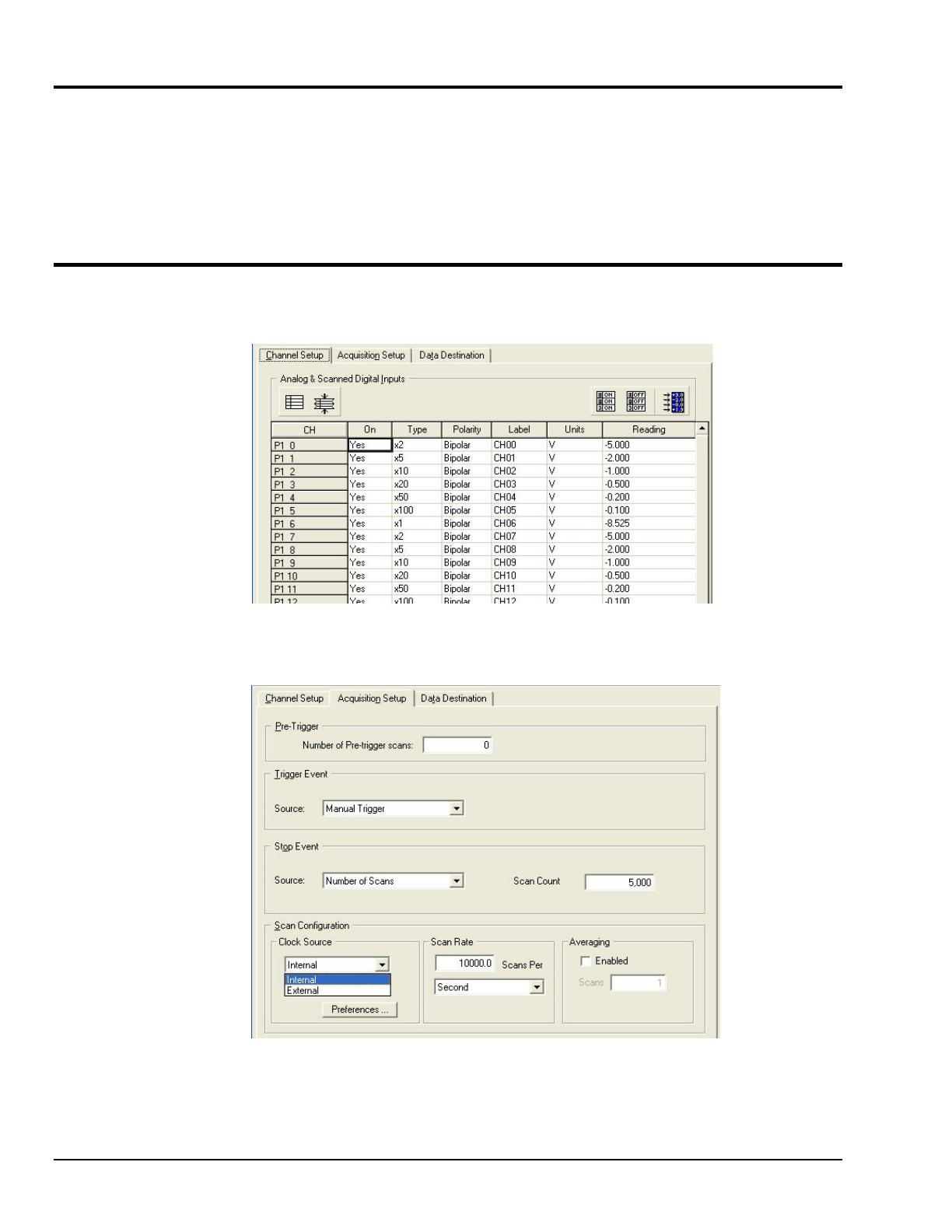
(4) Configure the System
The Channel Setup window (first tab on lower portion of main window) displays the analog and scanned
digital input channels and allows you to configure them.
Channel Setup Tab Selected
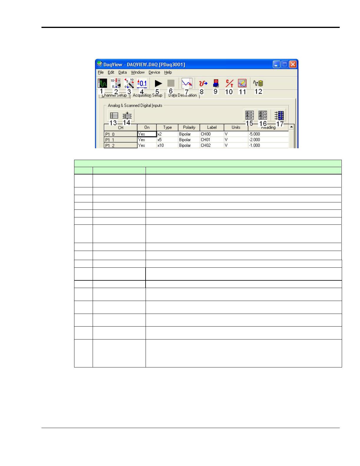
Selecting the second tab of the main window displays the Acquisition Setup window, used to set triggering
and configure the scan. These settings will be used when an acquisition to disk is started.
Acquisition Tab Selected
Note: The Data Destination window (not shown) lets you designate the directory for acquired
data and the desired file formats.
OMB-DAQ-3000 Series Installation Guide
988293 IG-9
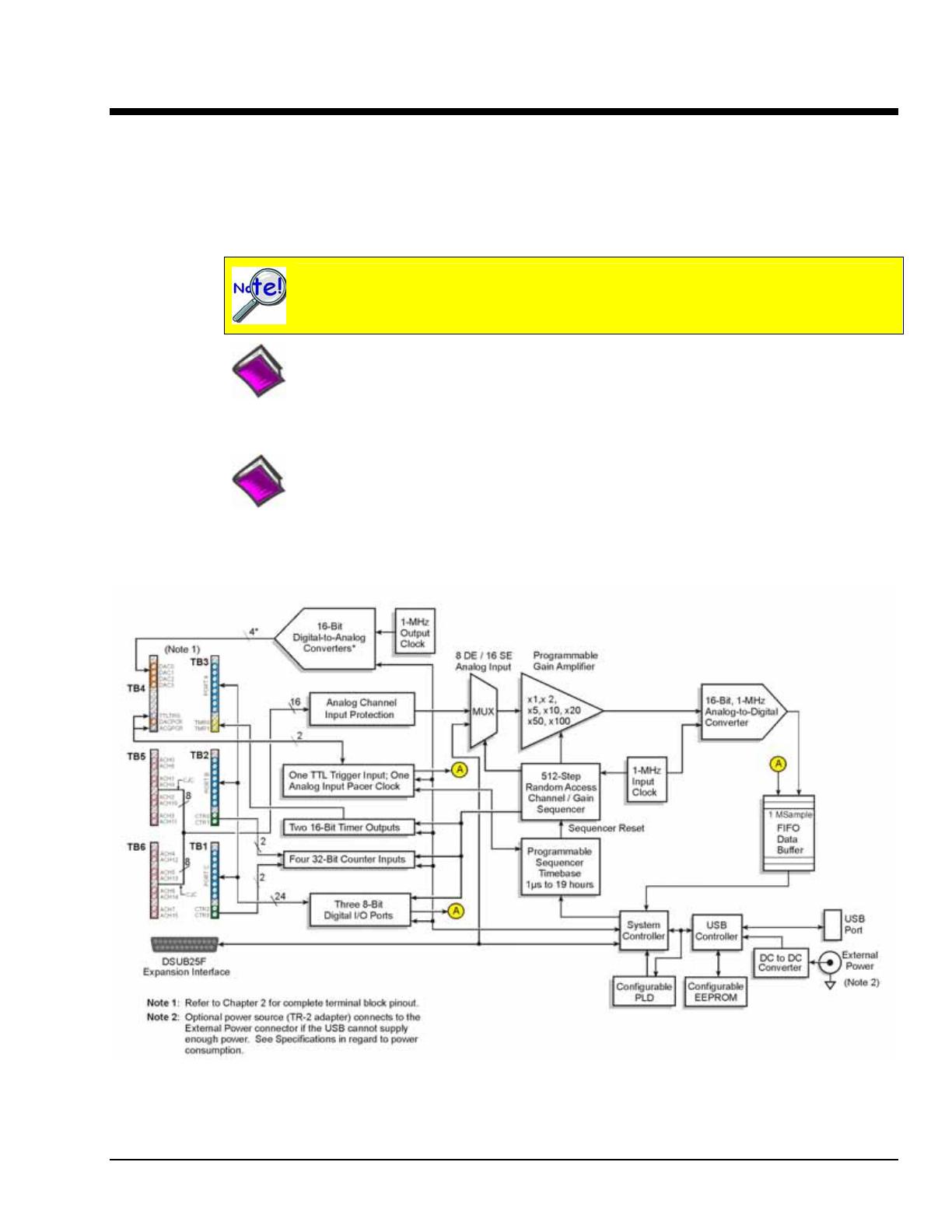
(5) Collect Data
Click the Enable Readings Column button (17), or the Start All Indicators button (5); the data acquisition
begins and the readings column becomes active. Click the Acquire button (12) to send the data to disk.
DaqView Main Window,
Channel Setup Tab Selected
Main Window, a Brief Description of Button Control Functions
#
Item Description
1 Scope Brings up a window from which Scope and/or Chart displays can be configured and used
for analyzing data in relation to x and y axes.
2 Bar Graph Meters Displays a bar graph meter.
3 Analog Meters Displays an analog dial meter.
4 Digital Meters Displays a digital meter.
5 Start All Indicators Starts displaying data in the Reading column and any open Chart or Meters window.
6 Stop All Indicators Stops displaying data in the Reading column and any open Chart or Meters window.
7 View File Data Launches an independent post-data acquisition program, such as
eZ-PostView, if installed. The data acquisition CD includes a PDF version of the post data
acquisition document.
8 Analog Output Displays the Analog Output window of the available DAC channels.
9 Digital I/O Displays the Digital I/O window.
10 Counter/Timer Displays the Counter/Timer window.
11 Waveform & Pattern
Output
Displays the Arbitrary Waveform and Streamed Output windows.
12 Acquire Activates an acquisition of data to a file.
13 Show ALL Channels Expands Analog & Scanned Digital Inputs spreadsheet to show all channels, whether
active or not.
14 Hide INACTIVE
Channels
Condenses the Analog & Scanned Digital Inputs spreadsheet, to hide channels that are
inactive.
15 Turn All Visible
Channels ON
Turns all visible channels ON. Hidden channels will remain off.
16 Turn All Channels
OFF
Turns all the channels OFF.
17 Channel Reading A toggle button that enables [or disables] the Channel Reading column of the Analog and
Scanned Digital Input spreadsheet. Some windows require the Channel Reading column
to be disabled when changing channels or other parameters. This command is also
available from the Data pull-down menu.
Click one of the toolbar’s display icon buttons to see your data in the form of a scope or meter display.
Button (1) brings up the scope window, which allows you to set up a scope and chart displays; buttons 2, 3,
and 4 are for: bar graph meters, analog meters, and digital meters, respectively. Note that you can
simultaneously view combinations of display types.

IG-10
988293 OMB-DAQ-3000 Series Installation Guide
Reference Notes:
o Refer to the DaqView PDF for information regarding that application.
o Refer to the OMB-DAQ-3000 Series User’s Guide PDF for hardware related
information, including pinouts and block diagrams.
o The default location for PDF documentation is in the Programs group, which can be
accessed from the Windows Desktop.
o The PDFs can also be accessed directly from the Data Acquisition CD via the
<View PDFs> button on the opening splash screen.
o The PDFs can also be accessed from our web site.
Customer Assistance
To report problems and receive support, call your service representative. Before calling for assistance,
please refer to the portions of the OMB-DAQ-3000 Series User’s Guide that are relevant to your situation.
The manual exists in Adobe Acrobat PDF format and can be accessed by clicking the <View PDFs>
button that appears on the data acquisition CD’s install screen. It is also installed in the Programs group on
your PC, during software installation.
When you call, please have the following information available:
• Hardware model numbers
• Hardware serial numbers
• Software version numbers for DaqView
• Windows Operating System
• Type of computer and features
When returning equipment use original shipping containers or equivalent to prevent shipping damage. In
addition to the above information, please be sure to include:
• The return authorization number (we provide you with this number after you contact us)
• The name and phone number of an individual who can discuss the problems encountered
• Any special instructions regarding return shipping
• A copy of troubleshooting notes and comments on tests performed and all problem-related conditions.
Device Overviews 1
Block Diagrams …… 1-1
Connections …… 1-2
Product Features …… 1-3
Software ……1-15
DaqView can only be used with one OMB-DAQ at a time. DASYLab and LabView can
be used with multiple modules. For multiple module use (via custom programming) refer
to the Using Multiple Devices section of the Programmer’s Manual.
Reference Note:
Programming topics are covered in the OMB-Programmer’s Manual (p/n OMB-1008-0901;
M3827). As a part of product support, this manual is automatically loaded onto your hard drive
during software installation. The default location is the Programs group, which can be accessed
through the Windows Desktop.
Reference Note:
For module details refer to Chapter 7, Specifications.
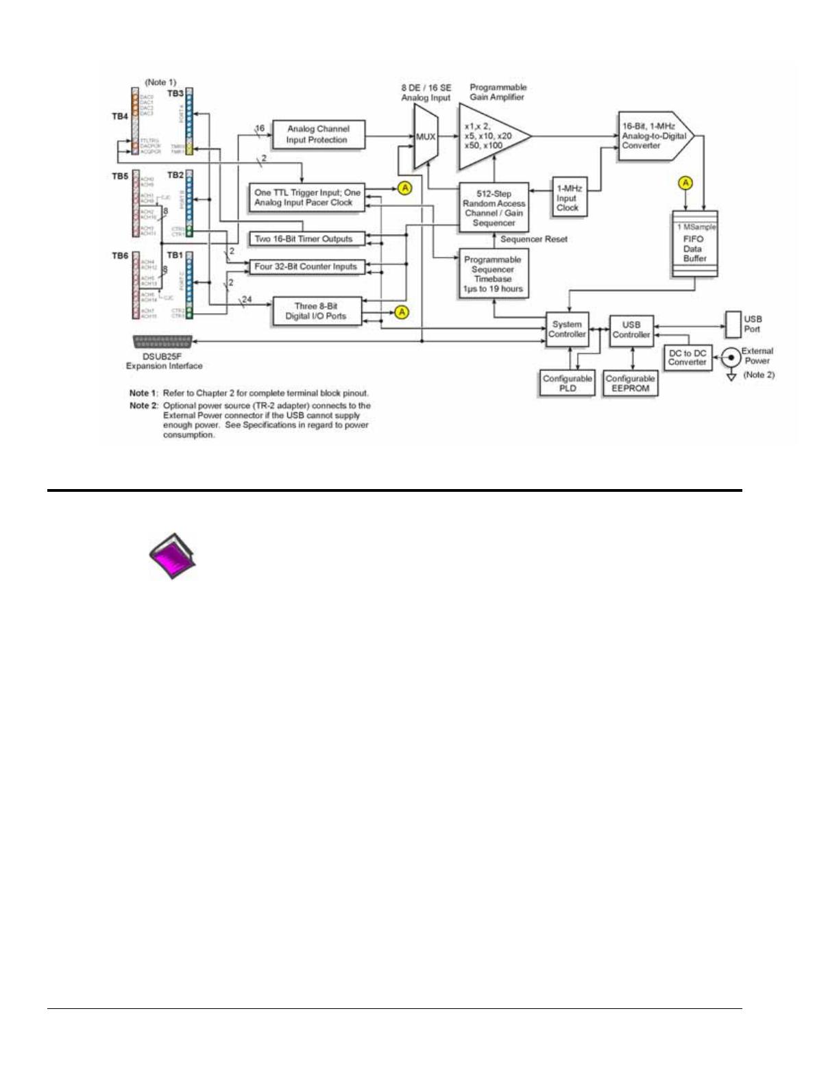
Block Diagrams
Block Diagram for OMB-DAQ-3000 and /3001
*
OMB-DAQ-3000 has two 16-Bit Digital-to-Analog Converters. OMB-DAQ-3001 has four 16-Bit Digital-to-Analog Converters.
OMB-DAQ-3000 Series User’s Manual 887894 Daq Systems and Device Overviews 1-1
1-2 Device Overviews
988793 OMB-DAQ-3000 Series User’s Manual
Block Diagram for OMB-DAQ-3005
Connections
Reference Note:
For the OMB-DAQ-3000 Series installation procedure, refer to the OMB-DAQ Installation
Guide (OMB-1136-0940; M4260). A copy of the guide is included at the beginning of this
manual.
USB2.0*
Used to connect the OMB-DAQ-3000 Series device to a host PC [or USB hub] via one of
the following cables: OMB-CA-179-1, OMB-CA-179-3, OMB-CA-179-5 (1 m, 3m, and 5m
lengths, respectively)
External
Power
Used to connect the device to an optional OMB-TR-2 external power supply when the host
PC’s USB connector cannot supply enough power or when an independent source of power
is desired.
DSUB25F
The 25-pin (female) connector can connect directly to an OMB-PDQ30, or can connect to
an OMB-PDQ30 indirectly via an OMB-CA-96A cable.
Screw
Terminal
Blocks
Six removable screw-terminal blocks provide connection for signal I/O. Each device in the
series supports 16SE/8DE Analog Inputs, 24 Digital I/O, 4 Counters, and 2 Timers. In
addition, the /3000 model supports 2 Analog Outputs; and the /3001 model supports 4
Analog Outputs. Connections are labeled on the devices. Pinouts are included in Chapter 2.
*
Use with USB1.1 will result in lower transfer speed which may not support continuous data collection at
high scan rates.

Product Features
I/O Comparison Matrix
Product or System Analog Input
Channels
Input
Ranges
Analog Output
Channels
Digital I/O
Channels
Counter
Inputs
Timer
Outputs
OMB-DAQ-3000 16SE / 8DE 7 2 24 4 2
OMB-DAQ-3001 16SE / 8DE 7 4 24 4 2
OMB-DAQ-3005 16SE / 8DE 7 0 24 4 2
OMB-DAQ-3000
with OMB-PDQ30
64SE / 32DE 7 2 24 4 2
OMB-DAQ-3001
with OMB-PDQ30
64SE / 32DE 7 4 24 4 2
OMB-DAQ-3005
with OMB-PDQ30
64SE / 32DE 7 0 24 4 2
The OMB-DAQ-3000 Series modules feature a 16-bit/1-MHz A/D converter, 16 analog input channels
[user expandable up to 64], up to four 16-bit/1-MHz analog outputs, 24 high-speed digital I/O channels,
2 timer outputs, and four 32-bit counters.
All analog I/O, digital I/O, and counter/timer I/O can operate synchronously and simultaneously,
guaranteeing deterministic I/O timing amongst all signal types. The OMB-DAQ-3000 Series modules
include a high-speed, low-latency, highly deterministic control output mode that operates independent of
the PC. In this mode both digital and analog outputs can respond to analog, digital and counter inputs as
fast as 2µsec.
Other Hardware Features Include:
o Encoder measurements up to 20 MHz, including Z-channel zeroing
o Frequency and Pulse-width measurements with 20.83 nsec resolution
o Timing mode: can measure the time between two counter inputs to 20.83 nsec resolution
o Self-calibration
The OMB-DAQ-3000 series offers up to 4-MHz scanning of all digital input lines. Digital inputs and
counter inputs can be synchronously scanned [along with analog inputs] but do not affect the overall A/D
rate because they use no time slot in the scanning sequencer. For example, one analog input can be scanned
at the full 1-MHz A/D rate along with digital and counter input channels. The 1-MHz A/D rate is
unaffected by additional digital and counter channels.
Adding analog input channels to an OMB-DAQ-3000 Series module is easy. An additional 48 single-
ended
[or 24 differential] analog input channels can be added to each module with the optional OMB-PDQ30
expansion module. The OMB-PDQ30 connects to the OMB-DAQ-3000 series card via an external cable.
With the OMB-DAQ-3000’s 1-MHz aggregate sample rate, users can easily add multiple analog expansion
channels and still have enough bandwidth to have a per-channel sample rate in the multiple kHz range.
Although the OMB-DAQ-3000 Series modules are powered via a USB port on a host PC, an external
power connector is available for cases in which the host PC’s USB port cannot supply adequate power, or
for when the user prefers a separate power source. The OMB-TR-2 is an optional power supply available
for this purpose. The OMB-TR-2 plugs into a standard 120VAC outlet and will supply 9VDC, 1 amp
power to the module via its external power connector.
OMB-DAQ-3000 Series User’s Manual 988793 Device Overviews 1-3

1-4 Device Overviews
988793 OMB-DAQ-3000 Series User’s Manual
Signal I/O
Six banks of removable screw-terminal blocks provide connectivity to the 16SE/8DE analog input
channels, 24 digital I/O lines, counter/timer channels, and analog outputs (when applicable).
Analog Input
The OMB-DAQ-3000 series has a 16-bit, 1-MHz A/D coupled with 16 single-ended, or 8 differential
analog inputs. Seven software programmable ranges provide inputs from ±10V to ±100 mV full scale.
Each channel can be software-configured for a different range, as well as for single-ended or differential
bipolar input. Each differential channel can accept any type of thermocouple input.
Synchronous I/O
The OMB-DAQ-3000 series has the ability to make analog measurements and scan digital and counter
inputs, while synchronously generating up to four analog outputs.
Additionally, while digital inputs and counter inputs can be synchronously scanned along with analog
inputs, they do not affect the overall A/D rate because they use no time slot in the scanning sequencer. For
example, one analog input can be scanned at the full 1-MHz A/D rate along with digital and counter input
channels. The 1-MHz A/D rate is unaffected by the additional digital and counter channels.
Input Scanning
OMB-DAQ-3000 Series devices have several scanning modes to address a wide variety of applications. A
512-location scan buffer can be loaded by the user with any combination of analog input channels. All
analog input channels in the scan buffer are measured sequentially at 1 µsec per channel. The user can also
specify that the sequence repeat immediately, or repeat after a programmable delay from 0 to 19 hours,
with 20.83 nsec resolution. For example, in the fastest mode, with a 0 delay, a single analog channel can
be scanned continuously at 1 Msamples/s; two analog channels can be scanned at 500K samples/seach;
16 analog input channels can be scanned at 62.5 Ksamples/s.
The digital and counter inputs can be read in several modes. First, via software the digital inputs or
counter inputs can be read asynchronously at anytime before, during, or after an analog input scan
sequence. This software mode is not deterministic as to exactly when a digital or counter input is read
relative to an analog input channel.
In either of the two synchronous modes, the digital inputs and/or counter inputs are read with deterministic
time correlation to the analog inputs. In the once-per-scan mode, all of the enabled digital inputs and
counter inputs are read during the first analog measurement of an analog input scan sequence. The
advantage of this mode is that the digital and counter inputs do not consume an analog input time slot, and
therefore do not reduce the available bandwidth for making analog input measurements. For example,
presume all 24 bits of digital input are enabled, and all four 32-bit counters are enabled, and eight channels
of analog inputs are in the scan sequence at full 1µsec/channel rate. At the beginning of each analog input
scan sequence, which would be 8 µsec in total duration, all digital inputs and counter inputs will be
measured and sent to the PC during the first µsec of the analog scan sequence.
Another synchronous mode allows digital inputs to be scanned every time an analog input channel is
scanned. For example, if eight analog inputs are scanned at 1 µsec per channel continuously, and 24 bits of
digital inputs are enabled, then the 24 bits of digital inputs will be scanned at 24 bits per 1 µsec. If counters
are enabled in this mode, they will be scanned at once per scan, in the same manner as in the first example
above.
Note: It is not necessary to read counters as often as it is to read digital inputs. This is because counters
continue to count pulses regardless of whether or not they are being read by the PC.

Example 1: Analog channel scanning of voltage inputs
The figure below shows a simple acquisition. The scan is programmed pre-acquisition and is made up of 6
analog channels (Ch0, Ch2, Ch5, Ch11, Ch22, Ch25.) Each of these analog channels can have a different
gain. The acquisition is triggered and the samples stream to the PC via USB2. Each analog channel
requires one microsecond of scan time therefore the scan period can be no shorter than 6 us for this
example. The scan period can be made much longer than 6 us, up to 19 hours. The maximum scan
frequency is one divided by 6us or 166,666 Hz.
Notice that some of the analog channels in the scan group are from an OMB-PDQ30 expansion module.
All analog channels are sampled at the same rate of 1us. Analog channels on the OMB-PDQ30 can also
have any of the gain ranges applied.
OMB-DAQ-3000 Series User’s Manual 988793 Device Overviews 1-5
1-6 Device Overviews
988793 OMB-DAQ-3000 Series User’s Manual
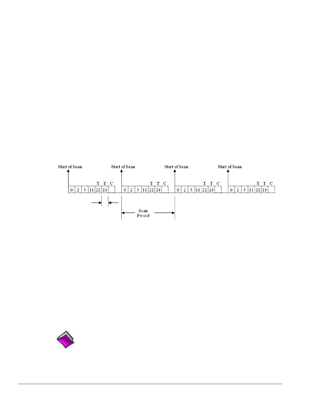
Example 2: Analog channel scanning of voltage and temperature inputs
The figure below shows a more complicated acquisition. The scan is programmed pre-acquisition and is
made up of 6 analog channels (Ch0, Ch2, Ch5, Ch11, Ch22, Ch23.) Each of these analog channels can
have a different gain. Two of the channels (22 and 23) are from an OMB-PDQ30 expansion module.
These two channels can be programmed to directly measure thermocouples. In this mode, oversampling is
programmable up to 16384 oversamples per channel in the scan group. When oversampling is applied, it is
applied to all analog channels in the scan group, including temperature and voltage channels. (Digital
channels are not oversampled.) If the desired number of oversamples is 256 then each analog channel in
the scan group will take 256 microseconds, the returned 16-bit value represents an average of 256
consecutive 1us samples of that channel. The acquisition is triggered and 16-bit values (each representing
an average of 256) stream to the PC via USB2.
Since two of the channels in the scan group are temperature channels, the acquisition engine will be
required to read a cold-junction-compensation (CJC) temperature every scan. In fact, depending upon
which OMB-PDQ30 channels are being used for temperature, there may be a CJC temperature required for
each temperature channel in the scan. Each 4 channel terminal block of the OMB-PDQ30 shares one CJC
so if all temperature channels are grouped on one (of the six) terminal blocks, then only one CJC
temperature measurement will need to be made per scan. For every OMB-PDQ30 terminal block that is
measuring at least one temperature channel, one additional CJC temperature measurement will be
automatically added to the scan group. This increases the scan period and reduces the maximum scanning
frequency.
Programmable
Averaging
up to 16384
In this example, the desired number of oversamples is 256, therefore each analog channel in the scan group
requires 256 microseconds to return one 16-bit value. The oversampling is also done for CJC temperature
measurement channels. The minimum scan period for this example is therefore 7 X 256 µs, or 1792
microseconds. The maximum scan frequency is the inverse of this number, 558 Hz.
Channels 0 through 7 of the OMB-DAQ-3000 can be used to measure temperature in place of voltage.
There are three CJC channels per analog input terminal block. When all 8 differential analog inputs are
used for temperature 6 CJC channels must be included as part of the scan group. This means when the
device is measuring all 8 temperature inputs and using oversampling of 256, the minimum scan period is
14 x 256 µs, or 3584 µs.
Autozero may also be employed. This adds more channels to the scan group and further reduces the
maximum scan frequency. Auto zero channels read a shorted analog input that is internal to the
OMB-PDQ30 or OMB-DAQ-3000 Series module. Auto zeroing reduces drift due to fluctuating ambient
temperatures or ambient temperatures outside the DC specifications.
Reference Note:
Appendix A includes detailed information regarding signal modes, methods of noise
reduction, and averaging techniques.
/