Davey 48501 Operating instructions
- Category
- Water pumps
- Type
- Operating instructions
This manual is also suitable for

Read All Instructions Before Installing Your New Prime Jet
These instructions have been prepared to acquaint you with the correct method of installing and
operating your Prime Jet Pressure System. We urge you to study this publication carefully and
follow its recommendations. If you have any installation difculties or need further advice you
should contact the Davey dealer from whom you purchased the system or the Davey Customer
Service Centre.
INSTALLATION AND OPERATING INSTRUCTIONS
PRIME JET 240
PUMPS AND PRESSURE SYSTEMS
Please pass these instructions on to the operator of this equipment.
Davey
®
Repair or Replacement Guarantee
In the unlikely event in Australia or New Zealand that this Davey product develops any malfunction
within two years of the date of original purchase due to faulty materials or manufacture, Davey will at
our option repair or replace it for you free of charge, subject to the conditions below.
Should you experience any difculties with your Davey product, we suggest in the rst instance that
you contact the Davey Dealer from which you purchased the Davey product. Alternatively you can
phone our Customer Service line on 1300 367 866 in Australia, or 0800 654 333 in New Zealand, or
send a written letter to Davey at the address listed below. On receipt of your claim, Davey will seek to
resolve your difculties or, if the product is faulty or defective, advise you on how to have your Davey
product repaired, obtain a replacement or a refund.
Your Davey Two Year Guarantee naturally does not cover normal wear or tear, replacement of product
consumables (i.e. mechanical seals, bearings or capacitors), loss or damage resulting from misuse
or negligent handling, improper use for which the product was not designed or advertised, failure to
properly follow the provided installation and operating instructions, failure to carry out maintenance,
corrosive or abrasive water or other liquid, lightning or high voltage spikes, or unauthorized persons
attempting repairs. Where applicable, your Davey product must only be connected to the voltage
shown on the nameplate.
Your Davey Two Year Guarantee does not cover freight or any other costs incurred in making a claim.
Please retain your receipt as proof of purchase; you MUST provide evidence of the date of original
purchase when claiming under the Davey Two Year Guarantee.
Davey shall not be liable for any loss of prots or any consequential, indirect or special loss, damage
or injury of any kind whatsoever arising directly or indirectly from Davey products. This limitation
does not apply to any liability of Davey for failure to comply with a consumer guarantee applicable to
your Davey product under the Australian or New Zealand legislation and does not affect any rights or
remedies that may be available to you under the Australian or New Zealand Consumer Legislation.
In Australia, you are entitled to a replacement or refund for a major failure and for compensation for
any other reasonably foreseeable loss or damage. You are also entitled to have the goods repaired
or replaced if the goods fail to be of acceptable quality and the failure does not amount to a major
failure.
Should your Davey product require repair or service after the guarantee period; contact your nearest
Davey Dealer or phone the Davey Customer Service Centre on the number listed below.
For a complete list of Davey Dealers visit our website (davey.com.au) or call:
* Installation and operating instructions are included with the product when purchased new.
They may also be found on our website.
P/N 48122-9 supersedes P/N 48122-8
AUSTRALIA
Customer Service Centre
6 Lakeview Drive,
Scoresby, Australia 3179
Ph: 1300 367 866
Fax: 1300 369 119
Website: davey.com.au
Davey Water Products Pty Ltd
Member of the GUD Group
ABN 18 066 327 517
NEW ZEALAND
Customer Service Centre
7 Rockridge Avenue,
Penrose, Auckland 1061
Ph: 0800 654 333
Fax: 09 527 7654
Website: daveynz.co.nz
® Davey is a registered trade mark of Davey Water Products Pty Ltd.
© Davey Water Products Pty Ltd 2011.

Prior to using this pump you must ensure that:
• The pump is installed in a safe and dry environment
• The pump enclosure has adequate drainage in the event of leakage
• Any transport plugs are removed
• The pipe-work is correctly sealed and supported
• The pump is primed correctly
• The power supply is correctly connected
• All steps have been taken for safe operation
Appropriate details for all of these items are contained in the following Installation and Operating
Instructions. Read these in their entirety before switching on this pump. If you are uncertain as
to any of these Installation and Operating Instructions please contact your Davey dealer or the
appropriate Davey ofce as listed on the back of this document.
INTRODUCTION
Davey Prime Jet Pumps and Water Pressure Systems have been designed to operate with one of
two alternative suction arrangements, these are:–
Shallow Well Injector for surface water Deep Well Injector for bore holes and/or deep
or shallow wells up to 7.5m (25ft) deep OR wells up to 50m (164ft) deep.
HOUSING YOUR PRIME JET
To avoid damage to your Prime Jet pump or system which may not be covered by the
guarantee, ensure adequate protection from external atmospheric conditions. The
housing of the product should protect against freezing, rain, extreme heat or other
adverse weather conditions. Adequate ventilation must be provided for the motor,
however, do not enclose the pump in such a manner that a “hot box” condition is created.
Ventilation should be provided near the top of any enclosure to prevent a “buildup” of
condensation.
Your Prime Jet should be mounted on a rm base high enough to prevent any surface water that
may accumulate from coming into contact with the unit. Positioning of the unit should allow the
nameplate to be easily read and adequate access for service purposes. Install so that any water
which, over time, leaks from pipe connections or pump seals can drain away without damaging
surrounds.
The power outlet may need to be provided by an electrician in a safe, dry place (possibly within the
weather proof enclosure). Prime Jet 240 1 phase, 220/250 units require a special 15 amp power
outlet.
INSTALLING A PRIME JET FOR SHALLOW WELL APPLICATIONS
(Where Total Suction Head is Less Than 7.5 Metres (25 ft.)
The Shallow Well Jet Kit is supplied separate from the pump or pressure system and includes a
rubber gasket. Place this rubber gasket over the 4 studs on the pump. Fit the jet assembly over
the studs on the pump and secure with the nuts and washers provided. Tighten nuts sufciently to
prevent air leaks around the gasket but do not over tighten.
TROUBLE SHOOTING
1. PUMP NOT DELIVERING WATER OR NOT BUILDING UP PRESSURE:
May be caused by one or more of the following:
a. Pump not properly primed;
b. Footvalve or checkvalve not installed or leaking;
c. Footvalve not installed below water level;
d. Suction lift too high;
e. Suction piping not correctly sealed or holed allowing air to enter pump suction;
f. Check valve installed in wrong direction;
g Blocked jet or venturi;
h. Piping connected in reverse on deep well, i.e. suction and pressure pipes transposed;
i. Motor thermal overload tripping - refer paragraph 3;
j. Insufcient water supply source;
k. Pressure system not switching on due to static delivery head causing higher pressure on
the pump than pressure switch cut-in.
2. PUMP NOT OPERATING AT MINIMUM OPERATING PRESSURE FOR DEEP WELL
INJECTOR:
a. Usually caused by air leaks in suction pipe.
3. MOTOR NOT RUNNING:
May be caused by one or more of the following :
a. Power failure;
b. Blown fuse;
c. Motor overload tripping;
d. Motor windings faulty.
4. MOTOR THERMAL OVERLOAD TRIPPING:
May be caused by one or more of the following :
a. Low voltage supply;
b. Motor or pump seized;
c. Motor windings faulty.
5. PUMP (AUTOMATIC SYSTEM WITH TANK) SWITCHING ON AND OFF FREQUENTLY OR
WHEN NO TAPS TURNED ON:
May be caused by one or more of the following :
a. Footvalve or checkvalve not retaining pressure or water;
b. Water leaking from suction or delivery piping;
c. Ball valve in toilet cistern, hot water system, or stock troughs incorrectly set or faulty;
d. Pressure tank not retaining air pressure or air charge too high;
e. Motor thermal overload tripping - refer preceding paragraph.
6. PUMP (AUTOMATIC SYSTEM WITH TANK) NOT SWITCHING OFF OR TAKING TOO
LONG TO SWITCH OFF:
May be caused by one or more of the following :
a. Voltage supply too low;
b. Blocked jet or venturi;
c. Leak in discharge pipe or ttings, taps etc.;
d. Worn or blocked pump components impeller, casing etc.;
e. Drop in water level in water supply source.
SPARE PARTS
When ordering spare parts it is essential to give both pump model and motor type numbers from
nameplate, and the full description of part required.
- 2 - - 11 -
The use of this product to pump
ammable, corrosive and other
materials of a hazardous nature is
specically excluded.
NOTE: For protection, the Davey pump motor is tted with an automatic “over
temperature” motor protection cut-out. Constant tripping of this overload device
indicates a problem eg. low voltage at pump, excessive temperature (above 45
o
C)
in pump housing / enclosure.
NOTE: Pipes should be sealed correctly so that they do not leak. Seals should
not visibly leak - visible leaks may indicate seal failure. Contact your Davey
Dealer.

To Check Correct Operation Of A Pressure System With Pressure Tank Fitted
Close gate valve at pump outlet. Allow pump to run and build up pressure until it switches off
automatically at the cut-out pressure setting on the pressure switch.
Open gate valve on pump outlet then turn on a tap in the outlet pipework. Pump should
automatically switch on at cut-in pressure switch setting. Refer to the “Pressure Switch Settings”
section earlier in these instructions.
MINIMUM OPERATING PRESSURE FOR DEEP WELL INSTALLATIONS
INJECTOR KIT NO. 427 428 468 566 567 568 569
Minimum Operating
Pressure kPa 280 280 280 270 270 290 240
Automatic Demand Response (ADR) - Setting up instructions
Deep Well installations require a certain minimum pump pressure to operate satisfactorily
(See Table above). With the adjustment screw on the ADR valve adjusted fully out run the pump.
Open gate valve (situated near pump) to discharge water freely until pressure on gauge drops
to minimum operating pressure as table above or until pump nears cavitation point. Screw ADR
valve adjustment in until pressure starts to rise. Open gate valve a little further, then readjust ADR
valve to maintain required minimum pressure on gauge. When gate valve is fully open and ADR
valve is maintaining operating pressure, adjustment is complete.
Once set, there should be no need to alter the setting of the ADR valve. ADR valve should be set
by discharging water adjacent to pump before connecting outlet pipework or pressure tank.
MINIMUM OPERATING PRESSURE FOR SHALLOW WELL INSTALLATIONS
Set the minimum operating pressures for Shallow Well pumps to the pressure indicated in the table
below.
INJECTOR KIT NO. 680 681 682 683
Minimum Operating
Pressure kPa 240 300 400 500
- 10 -
NOTE: The use of an engine powered pump to prime OFFSET deep well suction
pipes from the water source may simplify the priming process.
NOTE: Deep Well installation require a certain minimum reading on the
pressure gauge for the pump to operate satisfactory. If pump is allowed to
operate below this minimum operating pressure, cavitation may occur which
causes excessive pump wear, alternatively, prime may be lost.
NOTE: Shallow Well installations require a certain minimum reading on the
pressure gauge for the pump to operate satisfactorily. If pump is allowed to
operate below this minimum operating pressure, cavitation may occur which
causes excessive pump wear, alternatively, prime may be lost.
- 3 -
A foot valve must be used on the end of the suction pipe for below ground
installations or a check valve in the suction line for above ground water
sources (ie. tanks). For optimum pump operation and priming ensure that the
suction line is level or rises evenly from the water source to the pump.
Suction Piping
Polythene pipe is recommended for the pump suction as it provides exibility, reduces the
transmission of pump noises and provides a convenient method of disconnecting the pump without
unions or the need to cut into the piping. For best performance situate the pump as close to the
water source as practical. To reduce pipe friction and maximise ow we recommend the following
Suction Pipe Sizes for the lengths indicated.
Suction Port size 1
1
/
2
” BSP
Suction Length up to 10m 10m to 30m
Pipe size 40mm (1
1
/
2
”) 50mm (2”)
Use thread seal tape or pipe compound on all threaded pipe ttings or connections and ensure
they are leak free.
Suction piping should be laid so there is a constant rise from the water source to the pump.
Any high spots will cause air pockets to form and reduce the efciency of the system as well as
creating priming difculties.
Plumbing Details for ‘Shallow Well’ Installations
For Automatic Pressure System Installation.
NOTE: Suction leaks are the biggest cause of operating difculties and are hard
to detect because the problem is air leaking into the pipe and there may be no
external sign of the leak.

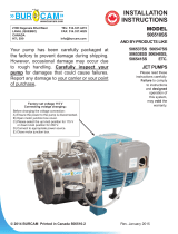
INSTALLING A PRIME JET FOR ‘DEEP WELL’ APPLICATIONS
(Total Suction Head over 7.5m or 25 ft) with Deep Well
Injector Kit.
The Deep Well Injector Kit comprises a bronze injector and foot
valve assembly which is to be attached to the end of polythene
piping and lowered into the water. An adaptor ange (or bend) to
connect the suction pipes to the pump is also included in the kit,
together with a rubber gasket and 2 polythene connectors and 8
stainless steel hose clips.
(A) Piping for use on Deep Well Injectors
All Deep Well Injectors require two pipes to be connected. Pipe
sizes are according to Table below (except where special sizes
may be specied for a particular installation).
DEEP WELL SUCTION PIPES DEEP WELL SUCTION PIPES
INJECTOR KIT I.D. INJECTOR KIT I.D.
100mm (4”) 125mm (5”)
427 & 428 1
1
/
2
” (38mm) & 565, 567, 568 2” (50mm) &
1
1
/
4
” (32mm) 569 1
1
/
2
” (38mm)
NOTE: Injector ttings are sized for imperial pipe.
Polythene piping which complies with the relevant Australian Standard should be used. Select the
grade of pipe which has a pressure rating of 90m head (300 ft.) for use on depths over 12 metres
(40 ft.). For depths up to 12 metres (40 ft.) polythene pipe with a pressure rating of 60m head
(200 ft.) may be used.
For “Offset” installations involving long runs of pipes to the deepwell injector, larger sized pipes
will be required to minimize resistance to ow and enable pump performance to be achieved.
Consult your Davey Pump Dealer or the Davey Customer Service Centre for recommendations.
AUTOMATIC DEMAND RESPONSE VALVE
Included in the Deep Well Injector Kit carton is the automatic demand response valve (ADR). The
ADR should be tted to the discharge elbow of the pump. A gate valve must be tted to the ADR
outlet before connection of the outlet piping. For ease of setting the ADR (see page 10) provision
must also be made to allow for temporary full open discharge of water after the gate valve.
OPERATING INSTRUCTIONS
OPERATING THE PUMP
(A) Shallow Well Installations
Close gate valve at outlet of pump. Remove the priming plug and ll pump body and suction
pipe by pouring water into the priming port on top of the pump or open gate valve on supply
reservoir to allow water to ow into pump. Air will be expelled as the suction pipe is lled with
water.
When all the air has “bubbled” out replace the priming plug. Do not run the pump without
water.
Switch on power to pump.
Crack air bleed screw on priming plug to expel trapped air.
Allow pump to run until a change in sound of pump indicates that prime is established and
pressure gauge reading rises to over 350 kPa.
Open gate valve at pump outlet.
A strong ow of water should be evident at an outlet tap indicating pump is functioning. If there
is no strong ow of water at the outlet tap or the pressure gauge reading drops away, reprime
the pump and repeat.
On long suction lines it may be necessary to re-prime several times to expel all the air from
the suction line to allow the pump to operate efciently.
To Check Correct Operation of a Pressure System with Pressure Tank Fitted
Close gate valve at pump outlet. Allow pump to run and build up pressure until it switches off
automatically at the cut-out pressure setting of the pressure switch. Open gate valve on pump
outlet then turn on a tap in the outlet pipework. Pump should automatically switch on at cut-in
pressure setting.
(B) Deep Well Installations
Ensure both suction pipes are full of water and all pipe connections are well sealed.
Fill pump by pouring water in at priming port on top of pump. Replace priming plug when all
air has “bubbled” out. Crack air bleed screw to expel trapped air.
Switch on power to pump.
Close gate valve at outlet of pump.
If correctly primed, pressure gauge reading will quickly climb to over 350 kPa.
On deep well installations it may be necessary to reprime several times to expel all the air in
the pipes.
Once prime is established slowly open gate valve at pump outlet.
A strong ow of water should be evident at an outlet tap indicating pump is functioning.
On OFFSET deep well installations the suction lines may not rise evenly from water source to
pump and so trapped air in a hump will prevent priming. A tee installed at the highest point in
both pipes may be used to add water at this point provided that it is well sealed and air tight
before pump operation.
NOTE: The use of an engine powered pump to force water up the suction pipe
from the water source may simplify priming long suction lines.
- 4 - - 9 -

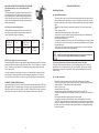
PRESSURE SWITCH SETTING (Applicable to Pressure System Models Only.)
Shallow Well Installations
For installations with shallow well jet kits it is necessary to set the pressure switch cut in and cut
out settings according to the table below. Instructions for altering the pressure switch setting are
under the cover of the switch.
MODEL Shallow Well Jet Kit Pressure Switch Setting
kPa psi
Prime 680 240-370 35-54
Jet 681 300-470 44-68
240 682 400-590 58-86
683 500-690 73-100
Deep Well Installations
Pressure systems to be installed with deep well injectors need no adjustment to the pressure
switch as the factory setting is satisfactory for all deep well injectors (210-350kPa, 30-50psi).
PUMP CONNECTIONS
(A) Pumps to be operated as Automatic Pressure Systems:
* Connect hose kit to Davey Supercell Pressure Tank and to bottom of outlet tee on pump as
shown in illustration. Firm tightness should be sufcient. Ensure tank connection hose is not
kinked.
* Fit gate valve to outlet tee of pump using thread seal tape.
* Connect delivery piping at gate valve.
* Fit pressure gauge on top of pump.
(B) Pumps to be operated Manually at Power Point:
* Disconnect pressure switch barrel union on top of pump then screw stainless steel self tapping
screw into pressure switch port to block it off.
* Reconnect barrel union.
* Fit gate valve to pump outlet (1
1
/
4
” Female) using thread seal tape.
* Connect delivery piping at gate valve.
* Fit pressure gauge on top of pump. A non-return valve may need to be tted in the delivery
piping on some installations to prevent water siphoning back through the pump. Consult your
Davey Dealer or the Davey Customer Service Centre.
PRESSURE TANK PRE-CHARGE (Applicable to Pressure System Models Only.)
The Supercell pressure tank requires the correct pre-charge of air for satisfactory operation. This
pre-charge of air is determined by the cut-in pressure switch setting for the particular system
purchased. Prime Jet 240 Supercell 30 Pressure Tanks are factory pre-charged to 245kPa (35psi)
which is suitable for a pressure switch cut in of 230kPa (33psi). To adjust for a higher cut in
pressure setting add air at the valve on top of the tank until the pressure is 15kPa (2psi) below the
proposed pressure switch cut in. Adjust this pre-charge before installing the pressure system.
A gate valve must be tted at the outlet of all pumps prior to the connection of
outlet piping.
(B) Plumbing Details for Deep Well Injectors.
A minimum submergence of 3m (10 ft.) is required for the injector and foot valve assembly for
correct operation.
When water is pumped out from a borehole it is common for the water level in the bore to drop.
However, there is usually a point at which the bore water level remains static or constant for a
given maximum ow from the bore. This new level is known as the draw down level of the bore.
It is necessary to establish this draw down level and the output capacity of the bore at this level
before installing a pump on the bore.
Once the pump has been installed on the bore it is necessary to regulate the ow from the pump
to ensure it does not exceed the maximum capacity of the bore at the draw down level. (Refer to
Operating Instructions included with Deep Well injectors).
The minimum submergence of the injector and foot valve assembly of 3 metres (10 ft.) means the
length of piping required from top of bore to injector assembly is equal to the draw down level plus
3 metres (10 ft.).
Furthermore, ensure that at least 2 metres (6 ft.) clearance exists between the injector assembly
and the bottom of the bore.
Having established the length of the piping required for attachment to the injector, connect the
injector assembly making sure that the larger pipe is tted to the long venturi tube of the injector.
Use 2 hose clips on each pipe connection and tighten securely. It may be necessary to heat the
polythene piping slightly before pushing it on to the hose tails. At the other end of the suction
pipes (top of bore end) t the adaptor ange to the piping using the hose tail connectors provided
loose in the injector kit.
Ensure joints are air tight, thread seal tape or pipe joining
compound is recommended. Securely tighten 2 hose clips on
each connector.
It is essential that there be no air leaks at this connection
particularly because air leaks are the biggest cause of
suction and priming difculties. Air being sucked in is almost
impossible to detect. Ensure that both pipes are of even length
and will lie straight side by side before installing in the bore
hole.
Lower injector assembly into bore hole and attach adaptor
ange to pump using the rubber gasket provided. Tighten the
nuts sufciently to prevent air leaks around the gasket but do
not over-tighten.
- 8 - - 5 -

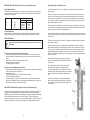
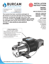
Davey recommend the use of overloads which also have the
ability to detect “single phasing” or “dropped phase” conditions in
the power supply.
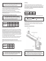
Three phase Prime Jet 240 models have been designed to allow
for connection either side of the Capacitor Cover (marked “A” in
gure one) on the motor. (NOTE: Three phase motors do not have
capacitors tted in the Capacitor Cover).
This is achieved by way of either of the two 19mm access holes
(marked “B” in gure one). The access holes are designed to
accept most standard cable grommets. The unused hole can be sealed by inserting the plug
enclosed with the pump. To connect a three phase Pressure Pump start by removing the Terminal
Cover (“C”)
A short four core ex (“D”) is tted from the motor terminals (“E”).
This lead is inserted through the blanking grommet (“F”).
Pressure switch or other control leads (“G”) can be tted as well.
Incoming power (“H”) can be tted through the preferred access
hole, and terminated as shown in Figure Three. A termination kit
is available if required.
Insert the blanking grommet (“F”) into the capacitor cover (“A”). Fix
the short lead (“D”) into the path provided in the non-drive endshield
and replace the terminal cover (“C”).
IMPORTANT NOTE: THREE PHASE MODELS ONLY
When the unit is connected and operating the phase balance should be checked. This should be
within 5% variation. “Rolling” the leads may help to improve a small unbalance, but major phase
unbalance will usually be attributed to an input power unbalance. This must be addressed before
the pump is used.
ADDITIONAL NOTES ON ELECTRICAL CONNECTION
1. If the electrical ttings in your area make it necessary to remove the plug tted to single phase
motors, care should be taken to ensure that the earth conductor is properly connected to
earth.
2. Long extension leads should be avoided as they often have insufcient current carrying
capacity to run electric motors; hence they can cause substantial voltage drop and operating
problems.
3. The minimum voltage at the electric motor must not fall below 216 Volts for 220/250V single
phase supply or 432 Volts for 480V single phase supply or 374 Volts for 3 phase supply.
Supply voltages below these limits may cause motor failure which is not claimable under
guarantee.
DELIVERY PIPING FOR SHALLOW OR DEEP WELL APPLICATIONS
It is recommended that a gate valve be tted at the outlet of the pump. Pipe connection ttings
which allow convenient disconnection at a future time should be used. Polythene piping which
complies with the relevant Australian standard is recommended. However, select the grade of pipe
which has a pressure rating suitable for your application. Galvanised or PVC piping may also be
used providing the pressure rating is adequate.
The pressure delivered by your Prime Jet is reduced by the static delivery head (vertical height
from pump to outlet point) plus the friction loss caused by the piping itself. Static delivery head
reduces the available pressure from the pump by 10kPa (2psi) for every 1 metre (3.3 ft) of head.
The reduction in pressure due to pipe friction varies with the length, diameter and type of piping
used. The larger the diameter pipe the smaller the pressure drop.
The following pipe sizes are recommended for lengths up to 100m (330 ft).
MODEL Outlet Up to Up to Up to
Port Size 5mm (15”) 30M (100’) 100M (330’)
Prime Jet 240 30mm (1
1
/
4
”) 30mm (1
1
/
4
”) 40mm (1
1
/
2
”) 50mm (2”)
POWER CONNECTION
Single phase Prime Jet 240 units are supplied with a special 15 amp power plug which may only
be used with a 15 amp 220/ 250V power outlet (usually specially provided by an electrician).
Single phase Prime Jet 240 units may also be wired to a nominal 480V power supply, but must be
reconnected at the terminals under the terminal cover (refer Figure One on pg 7).
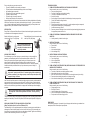
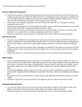
WIRING CONNECTIONS FOR SINGLE PHASE MOTORS
WIRING CONNECTIONS FOR THREE PHASE MOTORS
Prime Jet 240 units for connection to a nominal 415 Volt
3 phase supply must be wired with a contactor which has
quick trip (M10) rated overloads set at nameplate current. All
electrical connection work must be carried out by a suitable,
qualied electrician.
- 6 - - 7 -
In addition, the overload tted to the pump, is suitable for 240V only. 480V
overload is supplied in the bag in-which these instructions were supplied. All
this electrical work must be carried out by a suitably qualied electrician.
Before nalising wiring connections, check that motor rotates in direction of
arrow (clockwise when shaft is viewed from wiring connection end). To alter
rotation, change any two power leads at motor terminals.
Power connections and wiring must be carried out by an Authorised Electrician.
In accordance with AS 3350.2.41 we are obliged
to inform you that this pump is not to be used by
children or inrm persons and must not be used
as a toy by children.
Single phase
units should be
restricted to no
more than 20
starts per hour.
Note: Minimum three phase voltage supply at the motor must not fall below
374 volts, otherwise motor damage may result which is not claimable under
Guarantee.
-
 1
1
-
 2
2
-
 3
3
-
 4
4
-
 5
5
-
 6
6


Davey 48501 Operating instructions
- Category
- Water pumps
- Type
- Operating instructions
- This manual is also suitable for
Ask a question and I''ll find the answer in the document
Finding information in a document is now easier with AI
Related papers
-
Davey 165D3 Operating instructions
-
Davey 125S1T Operating instructions
-
Davey HM90-13 Operating instructions
-
Davey QB1501-C38 Operating instructions
-
Davey JY750 Operating instructions
-
-
-
-
-
Other documents
-
Everbilt AUTOJ100A3 Operating instructions
-
 Eco Flo EFCWJ7 FAQ
-
 Stairs ST Series Installation And Operating Instructions Manual
-
 BUR-CAM 8748139 Owner's manual
-
 BUR-CAM 506547SS Installation guide
-
 BUR-CAM 506538SS Installation guide
-
-
A.Y. McDonald 6010-007 Installation guide
-
 ProPlumber PPS3050 User manual
-
 ProPlumber PPS3050 User manual


