Page is loading ...

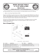
THIS STEP APPLIES ONLY TO THE 6735, WHICH
IS EQUIPPED WITH AN ALUMINUM SPINDLE TUBE:
Insert the aluminum tube through
the spindle hole in the safe door,
and hold the lock against the
safe door’s mounting plate. Mark
the tube 7/64" out from the front
surface of the safe door. Remove
the lock and cut the tube at your
mark. Make sure the cut is straight
and smooth, and remove any sharp
edges, burrs and cutting debris.
1. Using your fingers, pull the lock bolt to the fully
extended position. It should project approximately 1/2"
from the lock case when fully extended.
2. Remove the two Phillips head cover screws.
3. Remove the lock cover and set it aside.
4. Remove the drive cam and set it aside.
5. Align the spindle hole
of the lock case with
the spindle hole of the
safe door and securely
fasten the lock to the
safe’s mounting plate
by installing a 1/4 x 20
machine screw at each
corner of the lock case.
6. Seat the Delrin bushing into
the back of the dial ring,
and, using two 8-32 machine
screws, install the dial ring
to the front of the safe door.
Align the hole in the center
of the ring as closely as
possible with the spindle
hole in the door.
NOTE: If the lock is equipped with a tube, the dial ring
bushing will seat over the end of the tube.
7. Insert the dial’s spindle through the safe door and lock.
Thread the spindle into the drive cam until the lock dial
is snug in its ring and the drive cam is snug against the
wheel post of the lock. Mark the spot where the spindle
first projects through the drive cam.
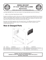
8. Remove the spindle
from the lock,
thread the drive
cam onto the
spindle until it is
between the dial
and your mark. Cut
the spindle at your mark, then file the new spindle end
until it is smooth and flat. Remove the drive cam from
the spindle to re-form any threads, which may have been
damaged in the cutting process.
9. Insert the dial’s spindle through the safe door and
thread it into the drive cam until snug. The end of the
spindle should now be nearly flush with the surface of
the drive cam.
10. Back the cam off the spindle
enough to align the slot
(spline keyway) in the spindle
with the slot in the drive cam,
which corresponds to the
mounting position of the lock
(RH, LH, VU, VD). If less than
1/2 turn is required to align the spline keyways, back the
cam off one extra revolution.
11. Insert a new, unused
spline key into the aligned
spindle and drive cam
slots. The flag of the
spline key should extend
over the body of the drive
cam and NOT cross the
end of the spindle. Using
a small, light hammer, tap the spline key until the flag
just touches the surface of the drive cam. Make certain
the spline key is a tight friction fit, or the lock will not
function properly.
12. Replace the lock’s cover and fasten it securely with the
cover screws.
13. Refer to operating and changing instructions for the
model of lock you have installed.
Standard 3-Wheel and 4-Wheel Group 2 and 2M Combination Locks
Mounting Instructions
Dokument: 630-738
Revised 3/9/2006
/