North Star M157594P.1 Installation, Operation and Maintenance Manual

Category
High-pressure cleaners
Type
Installation, Operation and Maintenance Manual

This manual is also suitable for

M157594P.1
Installation, Operation, and Maintenance Manual
HOT WATER PRESSURE WASHER: Cleans dirty surfaces with high
pressure hot water.
To the Owner:
Thank you for purchasing a NorthStar hot water pressure washer. Your machine is designed for long life,
dependability, and the top performance you demand! Take time now to read through this manual so you better
understand the machines’ operation, maintenance and safety precautions. Everyone who operates this machine
must read and understand this manual. The time you take now will prolong your machine’s life and prepare you
for its safe operation. Enjoy the exceptional performance of your NorthStar hot water pressure washer, the
industry leader! The manufacturer reserves the right to make improvements in design and/or changes in
specifications at any time without incurring any obligation to install them on units previously sold.
Quick Facts
Engine Oil Engine is shipped with out oil. Fill before starting. Use SAE 10W-30 motor oil.
Pump Oil Pump is shipped with oil. Check pump oil level before starting.
Water Make sure your water flow is 20% higher than the pressure washer’s flow rate.
Make sure your water is clean and particle free.
Storage Do not allow water to freeze in the pump, hose, coil, or spray gun.
Spraying
Chemicals
Use any NorthStar brand or equivalent pressure washer chemicals.
Adjust soap adjustment knob to regulate cleaning power.
Maintenance
Schedule
Engine: Oil: change after first 20 hours, then annually or every 100 hours.
Spark Plug: clean every 100 hours, replace annually or every 300 hours.
Air Filter: clean every 100 hours, replace annually or every 300 hours.
Pump: Oil: change after first 40 hours, then every 3 months or 500 hours.
Read and understand all manuals before operating.
Any Questions, Comments, Problems, or Parts Orders
Call NorthStar Product Support 1-800-270-0810
ITEM NUMBER: 157594, 157595
SERIAL NUMBER:
®
2
Table of Contents
Important Safety Instructions 2 Long Term/Winter Storage 12
Specifications 3 Troubleshooting Guide 13
Machine Component Identification 4 Parts Breakdowns 14-16
Installation Instructions 5-6 Electrical Schematic 17
Operation Instructions 7-9 Trailer Assembly Instructions (157595) 18
Safety Features 9 California Emissions Statement 19
Maintenance Instructions 10 Limited Warranty 21
Important Safety Instructions
WARNING -Risk of injection or injury to persons - Do not direct discharge stream at persons. - Do not use a
hose if exterior damage is evident.
-Risk of explosion. Do not spray flammable liquids. Do not operate in a flammable environment.
CAUTION -Risk of asphyxiation. Exhaust fumes are deadly. For outdoor use only. Avoid inhaling exhaust
fumes.
-Risk of fire. Do not add fuel when the product is operating or hot.
-Gun kicks back, hold with both hands.
-To reduce the risk of injury, read and understand operating instructions carefully before use.
WARNING - When using this product basic precautions should always be followed, including the following:
1.) Read all the instructions before using the product.
2.) To reduce the risk of injury, close supervision is necessary when the product is used near children. Do
not allow irresponsible use by children. Always stop the product and bleed pressures before leaving
unattended, disconnecting hoses, or servicing the pump.
3.) Know how to stop the product and bleed pressures quickly. Be thoroughly familiar with the controls.
4.) Stay alert - watch what you are doing.
5.) Do not operate the product when fatigued or under the influence of alcohol or drugs. Never smoke while
operating or fueling this machine.
6.) Keep operating area clear of all persons.
7.) Do not overreach or stand on unstable support. Keep good footing and balance at all times. Wear
footwear capable of maintaining a good grip on wet surfaces - Do not place the machine on soft or
unstable ground.
8.) Follow the maintenance instructions specified in all manuals. Do not run machine without sufficient
lubrication or sufficient water to cool the pump.
9.) Wear safety glasses, gloves, face protection and appropriate clothing when operating the machine.
10.) Do not operate this machine with broken or missing parts. - Never alter the manufacturer’s original
design or deactivate any safety device on the machine.
11.) Risk of exposure to dangerous chemicals. Wear protective gloves when handling and cleaning with
chemicals. Follow the chemical manufacturer’s directions. Understand all safety hazards and first aid for
all chemicals being used. Check whether dangerous chemicals have been used and take any
precautions that may have been recommended by the supplier of these chemicals when cleaning filters.
Do not pump highly abrasive fluids or use with incompatible chemicals or solvents.
12.) Know the pressure and temperature limits of your machine. Be sure all high pressure accessories meet
or exceed your machine’s limits. Do not set the pressure relief valve above the machine’s limit.
13.) Do not move this machine by pulling on the hose. Do not use the pump to support other items of
equipment that impose unacceptable loads on the pump. Do not attempt to use this machine as a prop.
14.) To reduce risk of injury, do not secure the spray gun open. Your spray gun is equipped with a built-in
trigger safety latch to guard against accidental trigger release and potentially dangerous high pressure
spray. Rotate the safety latch to the locked position when not spraying.
15.) Do not clean this machine with its own spray. Cleaning should be done with a damp sponge with the
engine OFF.
16.) NEVER attempt to immediately run or re-light the burner if it doesn’t ignite the first time. Unburned oil or
gas may have accumulated causing potential explosion or fire hazard.
17.) Always make sure all switches and controls are in the OFF position prior to starting the engine.
SAVE THESE INSTRUCTIONS
Specifications
3
Pressure Rating 4000 psi
Flow Output 4 gpm
Pump Type Cat 66DX
Water Supply Standard tap water @ 20-75 psi or water feed tank
Engine Horsepower 18 hp
BTU Output 353,700 BTU
Maximum Temperature
210° F
Approved Fuels #1 or #2 Diesel, Kerosene, Fuel Oil
Fuel Capacity 4 Gal
Gasoline Capacity 4 Gal
Discharge Hose 3/8”
Dimensions (skid only) 47” L X 37.5” W X 42” H
Weight (skid only) 500 lbs
Specifications for Trailer Mounted Models
Trailer GVWR 3500 lbs
Hitch Ball Size 2”
Skid Dimensions 129” L X 75.75” W X 60” H
Weight (tank empty) 960 lb
Weight (tank full) 2500 lb
Machine Component Identification
4
Ref # Description Ref # Description Ref # Description
1 Unloader 9 Ball Valve (feed tank) 16 Water Outlet
2 Lifting Eye 10 Ball Valve (city tap water) 17 Engine Key Switch
3 Engine (see engine manual) 11 Water Filter 18 Circuit Breaker
4 Inlet Plumbing 12 Water Inlet (city tap water) 19 Heat Switch
5 Diesel Tank (trailer models use hose reel) 20 Thermostat
6 Gasoline Tank 13 Control Panel 21 Indicator Light (pressure sw)
7 Pump 14 Battery Box 22 Indicator Light (thermostat)
8 Water Inlet (feed tank) 15 Pressure Switch
Installation Instructions
5
Installing a Battery
Warning: Sulfuric acid is a corrosive poison.
Avoid contact with skin, eyes or clothing. Always
wear safety glasses. Always wear safety glasses
when working on or near the battery.
The engine will not run and the burner will not fire
without first installing a battery.
The battery box provides protection for the battery and
will accept a standard automotive battery (The inside
dimensions are 11-1/8"L x 7-3/4"W x 10-1/8"H). The
battery must be 12VDC, with a minimum rating of 18 Ah
(Amp-hour). When installing a battery, always connect
the red colored (“positive” or “+”) cable first. When
disconnecting a battery, always remove the black
colored (“negative” or “-”) cable first
Location
IMPORTANT: Proper initial installation of equipment
will assure more satisfactory performance, longer
service life, and lower maintenance cost.
IMPORTANT: The use of a back flow preventer (Part
#222815 call 1-800-270-0810 to order) on the water
supply hose is recommended and may be required
by local code.
Place the pressure washer on a solid level surface in a
protected area where it is not readily influenced by
outside forces such as strong winds, freezing
temperatures, rain, etc. Locate the pressure washer for
easy access for filling fluids, adjustments, controls, and
maintenance. Position the machine so that ambient
lighting is sufficient for the surface you are cleaning to be
seen with ease. Use artificial light if needed.
Make a partition between the wash area and the
pressure washer to prevent direct nozzle spray from
coming in contact with the pressure washer. Moisture
reaching the equipment will reduce the pressure
washer’s service life.
Attaching a Water Feed Tank (157594 only)
Caution: Make sure to follow these instructions.
Inadequate plumbing between a feed tank and the
pressure washer can cause damage to the pump from
cavitation.
Cavitation will not occur if you select large fittings and
hose to connect the feed tank to the pressure washer.
Also, place the pressure washer right next to the feed
tank so the connection hose will be as short as possible.
1.) Use ¾” connection hose no longer than 6ft long.
2.) Make sure the connection hose does not kink.
3.) Make sure all fittings are ¾” or larger.
4.) Do not use 90° elbow fittings unless absolutely
necessary.
5.) Make sure bottom of the tank is level or higher than
the bottom of the skid frame.
6.) Do not pump flammable liquids or liquids containing
incompatible chemicals or solvents.
7.) Reroute the easy start valve so it discharges back to
the feed tank. This will aid pump priming on initial
start up. The easy start valve is located below the
unloader. See Machine Component Identification for
location of unloader.
Unloade
r
Plug this
p
or
t
Reroute hose to
water feed tank
Connec
t
feed line
here
Open
this ball
Close
this ball
Installation Instructions
6
Venting
DANGER: Do not run machine indoors or in an
enclosed area without adequate ventilation, or in
areas where flammable vapors, (gasoline, solvents,
etc.) may be present. Do not vent exhaust gases into
a wall, a ceiling, or a concealed place.
CAUTION: All venting must be in accordance with
applicable state and federal laws, and local
ordinances. Consult local heating contractors.
If the pressure washer is to be used in an enclosed area,
a flue must be installed to vent burner exhaust to the
outside atmosphere. Be sure the flue is the same size
as the burner exhaust vent on the pressure washer lid.
Poor draft will cause the pressure washer to soot and
not operate properly. When selecting the location for
installation, beware of poorly ventilated locations or
areas where exhaust fans may cause an insufficient
supply of oxygen. Proper combustion can only be
obtained when there is a sufficient supply of oxygen
available for the amount of fuel being burned. If it is
necessary to install a unit in a poorly ventilated area,
outside fresh air may have to be piped to the burner and
a fan installed to bring sufficient air into the unit. Locate
the pressure washer in such a manner that the flue will
be as straight as possible and protrude through the roof
at a proper height and location to provide adequate draft.
This oil fired unit must have a draft controller installed in
the flue. A draft controller will permit proper upward air
flow of exhaust flue gases.
Oil Burner
Burner Air Adjustment: The oil burner is preset and
performance tested at the factory (elevation 1100 feet).
Different altitudes may require a one-time initial burner
correction.
1.) Turn the engine and heat switches ON (Refer to
Operation” for details). Have someone operate the
spray gun so the burner fires.
2.) Loosen the locking screw and close the air band until
black smoke appears from the burner exhaust vent.
Note the position of the white arrow on the air band.
3.) Slowly open the air band until white smoke just starts
to appear.
4.) Turn the air band half way back to the black smoke
position previously noted. Tighten the locking
screw.
5.) Fine tune the burner air by loosening the shutter lock
screw and turning the shutter until the exhaust is
cleanest. Tighten the shutter lock screw.
CAUTION: If white smoke appears from the burner
exhaust vent during start-up or operation,
discontinue use and readjust air bands.
NOTE: If a flue is installed, have a professional
serviceman adjust your burner for a #1 or #2 smoke
spot on the Bacharach scale.
Locking
Screw
A
ir Band
Burner
White
A
rrow
Shutte
r
Lock Screw
Shutte
r
Operating Instructions
7
Read and understand the entire manual before operating the pressure washer.
Follow these instructions every time you use the pressure washer.
I.) Pre-Operation
Read entire manual, especially the important safety
instructions.
1.) Check hoses, fittings, wand, trigger gun and fuel
connections for signs of wear, cracks and
looseness, and replace as required.
2.) Check and clean the nozzle orifice.
3.) Check and clean the water inlet screen and filter.
(see Maintenance section).
4.) Check and maintain proper oil levels in the pump
and engine (see Maintenance section).
II.) Connecting City Water Tap
Follow these instructions when supplying water from a
pressurized source such as a garden hose instead of a
water feed tank.
Attach a garden hose to the water inlet (city tap water).
See Machine Component Identification for location of the
water inlet (city tap water).
1.) Make sure the water supply is clean. Debris can
cause excess pump wear and reduce performance.
2.) An insufficient water supply will damage your pump.
Make sure the water supply is steady and is 20%
over the rated flow of your pump. Use a stopwatch
to time how long it takes to fill a 5-gallon bucket with
your garden hose. It should take less than 62
seconds.
3.) The water supply garden hose must have an inside
diameter of at least 5/8”. If the hose is more than
100 ft. long, the diameter must be at least 3/4”.
4.) Always use a flexible rubber hose for your water
supply. Do not use rigid piping.
III.) Attach High Pressure Hose
Attach the high-pressure hose to the water outlet. See
Machine Component Identification section for location of
the water outlet
Your pressure washer hose is equipped with quick
couplers. Simply pull the collar back and push the
coupler onto the nipple. Make sure the collar slides over
the ball bearings. Once the connection is made, pull on
the hose to assure a positive connection.
Colla
r
Couple
r
High Pressure
Output
CORRECT
INCORRECT
Open this ball
valve
Close this
ball valve
Operating Instructions
8
V.) Turn Water Supply ON (city water tap
only)
Make sure the hose is not “kinked”. A kinked hose will
provide insufficient water supply to the pump and will
reduce its life. Make sure the hose remains unkinked
after moving the pressure washer.
VI.) Attach Nozzle
Color of Nozzle: Spray Angle Used For:
Red 0 Highest Impact
Yellow 15 Tough Stains/
Stripping
Green 25 General
White 40 Light Cleaning
Black 65 Chemicals
Your pressure washer is equipped with four high
pressure nozzles. To install a nozzle pull the collar back
and push the nozzle into the coupler. Once the
connection is made, pull on the nozzle to assure a tight
connection.
WARNING: Make sure the nozzle is correctly
inserted. The nozzle may become a projectile if not
inserted correctly. Do not attempt to use different
types of nozzles that may not fit the coupler.
VIII.) Applying Chemicals
WARNING: Only use NorthStar pressure washer
chemicals or chemicals specifically formulated for
pressure washers. Follow the chemical
manufacturer’s recommendations. Understand all
safety precautions and first aid for all chemicals.
NOTE: Your pressure washer is equipped with a low
pressure chemical injector. The proper chemical
used for the proper application can speed up
cleaning jobs tremendously.
A.) Snap the quick couple chemical injector onto the high
pressure outlet and high pressure hose and submerge
the suction strainer into the chemical solution.
B.) You need to use the low pressure black nozzle to
spray chemicals onto the cleaning surface.
C.) The amount of chemical applied can be changed by
turning the chemical adjustment knob located on the
chemical injector.
D.) Squeeze the spray gun trigger. The chemical
injector will draw the chemical into the water stream
E.) Apply chemicals evenly to the cleaning surface.
Allow the chemicals to react with the dirt, then clean at
high pressure with green nozzle.
F.) Never use more chemical than is necessary to clean
the surface.
G.) If you do not intend on using chemicals, we suggest
removing the chemical injector to obtain maximum
cleaning pressure.
IX.) Start Engine
See the engine manual to start your engine.
IMPORTANT: The water must be turned on (or water
feed tank filled) before starting. Running the pump
dry will cause damage and void the warranty.
Make sure only one ball valve is open. The ball
valve that you are not using needs to be closed
before starting the engine. Pump cavitation can
occur.
WARNING: Do not inhale the exhaust from the
engine. Do not point the lance at anyone even if the
engine has stopped because there could be a
release of water under retained pressure if the spray
gun trigger is actuated.
Straine
CORRECT
Chemical Injecto
r
INCORRECT
Hi
g
h Pressure Hose
Nozzle
Collar
Coupler
00322
High Pressure
Output
Lance
Diluted
Chemical
A
djustment Knob
Operating Instructions
9
X.) For Hot Water
If HOT water is desired, make sure there is fuel in the
fuel tank, turn the heat switch ON, and adjust the
thermostat to the desired temperature. The burner will
fire when the trigger is squeezed. You may need to
initially adjust your burner for peak performance. See
the “Oil Burner” section under INSTALLATION. When
the trigger is released a pressure switch automatically
turns the burner off. Also, when the temperature setting
is reached, the thermostat automatically turns the burner
off.
IMPORTANT: Do not run the machine in hot mode
without any fuel in the fuel tank. The fuel pump will be
damaged if it is run dry.
Warning: It is important that the burner stops firing when
the trigger is released. If the burner remains firing,
discontinue use until the pressure washer is serviced.
Extremely high temperatures can result in serious injury
and equipment damage.
XI.) Cleaning
WARNING: Wear eye, ear, hand, foot and skin
protection at all times while operating this pressure
washer.
DANGER: Do not point the spray wand at yourself or
at any person. Bodily injury may result from water
under high pressure.
CAUTION: Be careful on painted or delicate
surfaces. The pressure may damage the surface if
the nozzle is too close.
IMPORTANT: Your spray gun is equipped with a
built-in trigger safety latch to guard against
accidental trigger actuation and potentially
dangerous high pressure spray. Rotate the safety
latch to the locked position when not spraying.
A.) Hold the lance with two hands, have a sturdy stance.
B.) The pressure washer is set and locked to the
maximum rated pressure when it leaves the factory. .
WARNING: Do not alter the unloader valve’s
maximum pressure. Excess pressures could
cause serious injury and/or pump damage. Any
alteration other than turning the adjustment knob
will void your warranty.
XII.) Shut-Down Instructions
WARNING: Do not leave an operating machine
unattended. Always shut the machine OFF and
relieve the pressure before leaving the machine.
Never disconnect the high-pressure hose from the
pump or spray gun while the system is pressurized.
Relieve pressure by squeezing the spray gun trigger
after the engine is turned OFF.
A. Turn heat switch OFF and run cold water
through the coil for 3 minutes.
B. Turn engine OFF.
C. Turn water supply OFF.
D. Actuate spray gun trigger to relieve system
pressure.
E. Remove garden hose.
F. Remove pressure hose.
Safety Features
Safety Relief Valve
The safety relief valve is a backup safety feature. If the
system over pressurizes, the safety relief valve will open
and relieve system pressure.
The safety relief valve is located in the high pressure line
between the unloader and the heat exchanger.
WARNING: If the safety relief valve ever discharges
water, turn the engine off and do not use the
machine until it is serviced.
Thermal Relief Valve
The thermal relief valve allows the pump to remain in
bypass without risk of overheating the pump. If high
temperatures are developed during bypass, the thermal
relief valve will open and discharge hot water onto the
ground.
The thermal relief valve is located on the unloader
bypass port.
00417
Safet
y
Latch
Maintenance Instructions
10
WARNING: Unauthorized machine modification or use of non-approved replacement parts
may cause personal injury and/or property damage and will void the manufacturer warranty.
See Engine manual for engine maintenance.
Maintenance Mode
Before performing any maintenance on the pressure
washer, it must be placed in maintenance mode.
A.) Turn off water supply.
B.) Relieve pressure from system.
C.) Turn off engine and disconnect the spark plug cable.
Water Filter
Check whether dangerous chemicals have been
used, and take precautions when handling filters.
Before each use, remove filter screen and rinse with
clear water.
Burner Fuel Filter
Drain water from the fuel filter bowl and replace the filter
as needed.
Changing The Pump Oil
*Change oil after first 40 hours, then every 3 months or
500 hours
1.) Open oil drain valve.
2.) Drain pump oil.
3.) Close oil drain valve.
4.) Fill pump middle of sight glass with Cat pump oil or
30 wt. non-detergent oil.
5.) Oil Capacity is 18oz.
Checking the Hoses
WARNING: Do not use a finger or skin to check for
leaks. Escaping fluid under pressure has sufficient
force to penetrate the skin, causing serious injury.
Do not operate the pressure washer if the hose is
cracked, worn, or leaking.
Before each use check all hoses for leaks and worn
areas. Discontinue use of any hose if leaks are noticed.
Discontinue use of the high pressure hose if the wire
mesh is exposed.
Electrodes
Inspect electrodes annually.
Clean off carbon deposits, which may have accumulated
on the tips of the electrodes.
Reset the spacing as shown below.
1/16”
1/8”
5/16”
Electrodes
Oil drain
valve
Sight
glass
Oil fill
Maintenance Instructions
11
Coil Descaling
In hard water areas, scale build-up within the heating coil
will occur. Scale deposits will decrease the water
temperature rise and may eventually clog the heating
coil.
1. Mix coil cleaner in a 5 gallon bucket and elevate the
bucket so it is higher than the unloader.
2. Attach the high-pressure hose to the high-pressure
water outlet on the machine. Do not hook up the
spray gun.
3. Place the other end of the high-pressure hose in the 5
gallon bucket.
4. Attach a short length of hose to the garden hose inlet
on the pump.
5. Prime the pump by filling the hose with water, then
place the end of the hose in the bucket.
6. Run the pressure washer in cold mode for 1 to 3
hours re-circulating the cleaning solution.
Warning: Do not run the burner.
7. Dispose of the cleaning solution where it is not
harmful to animals or the environment.
8. Flush with fresh water and clean the inlet strainer
when finished.
Coil Desooting
Poor grades of fuel oil or inadequate combustion air will
cause heavy soot build-up on the outside surface of the
heating coil. These deposits will insulate the coil. This
will restrict the airflow through the coil, further
aggravating the soot build-up.
Most coils will never require desooting. However, to
desoot a coil...
1. Wear protective clothing, goggles, and gloves.
2. Disconnect high-pressure hose on inlet side of coil
and thermostat on outlet side of coil.
3. Remove the lid and insulation lid from the heating
chamber and hoist the coil out. Be careful, the coil
weighs 125 lbs.
4. Clean the coil.
5. Reassemble the coil to the machine. Make sure the
white insulation remains in place.
6. Reattach high-pressure hose and thermostat, and
make sure all fittings are tight before using the
machine.
Long Term / Winter Storage
12
During cold weather, store the pressure washer indoors and move it outdoors before starting the engine.
Long Term Storage and Freeze Protection
1.) Attach a feed tank or bucket to the water inlet (feed tank). See Installation section for Attaching a Water Feed Tank
instructions.
2.) Fill feed tank with 5 gallons of RV antifreeze.
3.) Run the pressure washer in cold mode until RV antifreeze comes out the water outlet. Make sure excess antifreeze is
disposed of safely. RV antifreeze will save the components from freeze damage and keep them lubricated.
4.) Disconnect spark plug cable. Make sure the engine start switch is OFF.
5.) Disconnect the battery and store it indoors.
Short Term Freeze Protection
1.) Drain water from feed tank.
2.) Drain water from the heat exchanger by extending the high pressure hose straight. Place the end of the hose at a
level that is below the pressure washer. Remove the spray gun from the hose. Disconnect the plumbing that
connects to the heat exchanger inlet. The water will flow out of the heating coil. This will protect the coil from freeze
damage.
3.) Open both water inlet ball valves and remove the cap from the water filter. This will drain the pump and water inlet
plumbing.
Troubleshooting Guide
13
Engine Will Not Start
Causes Solutions
Low Oil Shutdown Fill engine with the adequate amount of oil.
Cold Engine Choke engine to start.
No Fuel Add gas to engine, make sure fuel shutoff valve is open.
Dead Battery Recharge/Replace battery.
Spark plug wire not attached Attach spark plug wire to spark plug.
Pressure Washer Runs But Burner Doesn’t Fire
Causes Solutions
Heat switch turned OFF Turn heat switch ON.
Thermostat set too low or off Set thermostat to desired temp.
Fuel tank empty Fill fuel tank with kerosene, diesel, or fuel oil.
Defective Pressure Switch Call Product Support.
Defective Burner Call Product Support.
Pressure Washer Runs But No Pressure
Causes Solutions
Partially clogged or damaged nozzle Clean or replace nozzle.
Clogged water filter Clean water filter.
Low water flow Make sure the water supply is more than 4 gpm.
Pressure Washer Surges Or Cycles While In Bypass
Causes Solutions
Leak between unloader and gun. Check all connections between unloader and gun for leaks. Tighten loose
components and replace damaged components.
Gun leaking internally Replace spray gun.
Smoke From Heat Exchanger
Causes Solutions
Air band not adjusted properly Adjust the air band until the burner burns cleanly. See Installation Instructions
Poor quality fuel Use kerosene for the cleanest burn.
Water Not Heating Sufficiently
Causes Solutions
Scale build-up in coil See Coil Descaling under Maintenance Instructions.
Coil is full of soot See Coil Desooting under Maintenance Instructions.
Poor Or No Detergent Supply
Causes Solutions
Soap control knob set too low. Adjust soap control knob.
Inadequate detergent supply Refill detergent container. Make sure chemical strainer is fully submerged.
High pressure hose too long Use less hose. Move machine closer to the work.
Chemical strainer or injector clogged Clean the strainer and injector. Always start with a clean detergent container. Run
clean water through the injector after each use.
Any Questions, Comments, Problems, or Parts Orders
Call NorthStar Product Support 1-800-270-0810
Parts Breakdown 157594P.1
14
Component List – 157594P.1
15
REF PART # DESCRIPTION Model QTY REF PART # DESCRIPTION Model QTY
783394 Honda engine 18hp All 1 58 777721 Decal, side panel All 2
1
783396 Honda muffler kit All 1 59 777647 Battery box All 1
2 30511 1/2” npt plug All 1 60 777489 Battery strap All 1
3 777837 3/8” npt plug All 1 61 82233 Carriage bolt, 5/16” threads All 2
4 38198 CAT pump, 4gpm All 1 62 KEL201071 Cap, fuel tank All 1
5 777347 3/8” npt tee All 2 63 777727 Tank, Diesel All 1
6 777378 Hose, 18" 5400psi All 2 64 783029 Gasoline tank All 1
7 777682 Pressure gauge, 6000psi, 1/4” npt All 1 65 783034 Tank support All 1
8 777338 Reducer 3/8” npt x 1/4” npt MxF All 3 66 777838 1/4” NPT plug 157594 2
9 777410 Elbow 3/8” npt MxF All 3 67 781999 Thermostat All 1
10 17141 Hose clamp 3/4 hose All 4 68 777855 Toggle switch All 1
11 30289 Clear PVC hose, 3/4” All 12.5in 69 31085 Circuit breaker, 20A All 1
12 777671 Hose barb 1/2” npt M x 3/4”hose All 1 70 777644 Control box cover All 1
13 778829 Hose barb elbow 3/4npt M x 3/4hose All 1 71 777646 Red LED, 12VDC All 2
14 250142 Strainer, 3/4” npt FxF All 1 72 777660 Decal, control panel All 1
15 780413 Nipple 3/4” npt x 3/4” npt MxM All 1 73 777643 Control box panel All 1
16 39206 Tee 3/4” npt MxFxF All 2 74 36138 Relay 12VDC All 1
17 35442 Ball valve 3/4” npt FxF All 2 75 777645 Hose barb 1/2” npt F x 1/2” hose 157594 1
18 5023 Hose barb 3/4” npt x 3/4” hose All 1 76 305267 Nut, 1/2” npt 157594 2
19 35443 Elbow 3/4” npt x 3/4” npt MxM All 1 77 30483 Garden hose inlet, 1/2" npt M 157594 1
20 82220 U-bolt All 2 78 5232 Washer, garden hose 157594 1
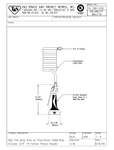
779269 Elbow 3/4” npt M x 1/2” HB 157594 1 778946 Nozzle 0 degree #4, red All 1
21
780432 Elbow 3/4” npt M x 3/4” HB 157595 1 25309 Nozzle 15 degree #4, yellow All 1
777119 Hose clamp 1/2” hose 157594 5 778948 Nozzle 25 degree #4, green All 1
22
17141 Hose clamp 3/4” hose 157595 2 778947 Nozzle 45 degree #4, white All 1
2264 Low pressure hose, 1/2” 157594 27in
79
778949 Nozzle, chemical, black All 1
23
30289 Clear PVC hose, 3/4” 157595 67in 80 777111 Grommet, nozzles All 5
24 779268 Hose barb 3/4” npt M X 1/2” hose All 1 81 38578 Knob, 5/16” thread All 2
25 2264 Low pressure hose, 1/2” All 7in 82 30289 Clear PVC hose, 3/4” All 40in
26 30048 Reducer 1/2” npt x 3/8” npt MxF All 2 83 22393 Relief valve, 3/8” npt All 1
27 32808 Elbow 3/8” npt M x 1/2” HB All 1 84 38379 Swivel, 3/8” npt x 1/2” npt MxF All 1
28 777340 Hose barb 1/4” npt M x 1/4” hose All 3 85 5027 Elbow, 1/2” npt MxF All 1
29 38584 Easy start valve, 3/8” npt M All 1 86 777652 Lid w/ rain cap All 1
30 777834 Hose clamp 1/4” hose All 9 87 305410 Decal, caution hot All 1
31 777165 Clear PVC hose, 1/4” All 12" 88 36302 Fiberglass rope, 5/8" All 39in
32 782123 Unloader All 1 89 38398 Insulation, cap All 1
33 777337 Nipple 1/2” npt x 3/8” npt MxM All 3 90 779228 Heating coil All 1
34 777409 Unloader block All 1 305278 Heat shrink tube
All
2in
35 777656 Pressure switch All 1
91
30501 Split loom
All
24in
36 777411 Tee 3/8” FxFxF All 2 92 305208 Tee 1/2” npt FxFxF All 1
37 777667 Battery cable, red All 1 93 777915 Quick couple nipple, 3/8” npt F All 1
38 777668 Battery cable, black All 1 94 779614 Injector, quick couple All 1
39 31881 Reflective sleeve All 14in 95 777165 Clear PVC hose, 1/4” All 48in
40 777345 Fuel line, 1/4” All 42in 96 221222 Strainer, chemical hose All 1
41 35743 Warning label All 1 97 777661 Wire harness, burner All 1
42 35413 Drain valve All 1 98 22502 Strain relief All 1
43 30746 Hose clamp 3/8” hose All 1 99 777669 Burner DC All 1
44 30290 Clear PVC hose, 3/8” All 14in 100 777345 Fuel line, 1/4” All 22in
45 777836 Thermal protector, 1/2” npt All 1 101 777345 Fuel line, 1/4” All 15.5in
46 777904 Quick coupler, 1/4” npt F All 1 102 32308 Fuel filter, water separator All 1
47 777421 Spray lance All 1 103 305239 Nipple 1/4” npt MxM 3" long All 1
48 777420 Spray gun All 1 104 38120 Insulation gasket All 1
49 777422 Quick coupler, 3/8” npt M All 1 105 36180 Stainless wrap All 1
50 777396 Hose, 50ft 5400psi, includes 51+52 All 1 106 779232 Fire chamber All 1
51 777722 Quick coupler, 3/8” npt F All 1 107 33387 Insulation, can All 1
52 777723 Quick couple nipple, 3/8” npt F All 1 108 783036 390cc carbon canister All 1
53 777475 Skid frame 157594 1 109 783037 Carbon canister strap All 1
54 777488 Heat shield, tanks All 1 110 784769 Sealed fuel cap All 1
55 777486 Heat shield, battery All 1 111 783218 Purge port cap All 1
56 783035 Tank clamp All 1 112 783212 1/4” MPT hose barb elbow All 2
57 777666 Decal, gasoline All 1
113 777345 Fuel line, 1/4”
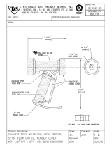
All 37”
Parts Breakdown – 157595P.1
16
REF PART # DESCRIPTION QTY
1 783427 Hose Reel 2 20 5370 Bulkhead ¾” NPT Female 3
3 777903 Frame, Skid 1 21 50NBR12 ½ Hose Barb x ¾ NPT Elbow 1
4 30198 200 Gal Tank 1 22 17141 Hose Clamp ¾ 1
5 777707 Tank Strap 2 23 30289 ¾ Clear PVC Hose
6 82080 Eye Bolt, ¼” 4 24 50CSC128 3/4” –1/2” Reducer 1
7 780200 15” Wheel 2 25 30048 1/2” – 3/8” Reducer 1
8 777771 Trailer Frame 1 26 777338 3/8” – 1/4” Reducer 1
9 127432 Trailer Light Kit (rear, front, wires) 1 27 777340 ¼” NPT x ¼” Hose Barb 1
10 38485 Pin 1 28 17141 1/4” Hose Clamp 2
11 783097 Jack 1 29 777165 1/4“ Clear PVC Hose 12”
12 783098 Wheel for Jack 1 30 777779 150' 3/8" 5400PSI Hose 1
13 777775 Coupler 1 31 779801 Truck Chest 1
14 782938 A-frame Tow bar 1 32 777914 QC 3/8” Female Coupling 1
15 779542 Safety Cables 2 33 777410 3/8” Street Elbow 1
16 39166 Axle 1 34 777378 18” 3/8” 5400 PSI Gray Hose 1
17 779782 Hose Reel Mount 2 35 779816 3/8 MPT x ½ FPT Adapter 1
18 35442 Ball Valve 1 36 777671 ½ NPT x ¾ Hose Barb 1
19 5318 Nipple ¾ NPT x ¾ Hose Barb 1 37 783099 Jack Plate 1
38 783426 3/8” Swivel Fitting 2
Wiring Diagram – Rev P.1
17
Trailer Assembly Instructions (157595 only)
18
1.) Remove the top and four sides of the steel crate.
2.) Remove a-frame from trailer frame. (keep
fasteners for step 7)
3.) Slide a-frame into holders under trailer frame
(built into the front posts).
4.) Install jack onto a-frame with 3/8x1” bolts, Class
G lock nuts, and washers provided. Tighten to
37ft/lbs.
5.) Slide caster wheel onto jack and secure with pin.
6.) Crank jack down until a-frame becomes level.
7.) Attach a-frame to trailer frame with six 5/8” bolts
and Class G nuts. Tighten to 180ft/lbs.
8.) Check trailer light wire routing though a-frame,
make sure wires are not pinched, stretched, or
pass any rough edges.
9.) Crank jack down farther (so a-
frame goes up) to take weight off
front shipping posts.
10.) Remove front shipping posts.
11.) Crank jack up as far as it will go
(so a-frame goes down and
weight is applied to wheels)
12.) Disconnect rear shipping posts
from frame (remove only the bolts
at the top of the rear shipping
posts)
13.) Roll trailer forward until it is free of
the rear shipping posts.
14.) Attach coupler to a-frame with two 1/2x4” bolts and
Class G lock nuts. Tighten each bolt to 90ft/lbs.
15.) Attach safety cables to the a-frame with ½”x 5” bolt
and Class G lock nut. Place a flat washer next to
the head of the bolt, slide the bolt through the cable
and the a-frame. Then slide the other cable onto
the bolt, followed by another washer then the lock
nut. Tighten to 37ft/lbs.
16.) Attach truck chest to a-frame with four 5/16x1”
bolts, lock nuts, and washers. Insert bolts down
though holes in truck chest and a-frame. Place
washers under wall of a-frame and fasten with lock
nuts. Tighten each bolt to 20ft/lbs.
A
-
frame
Caster
Jack
Trailer
Frame
Front Shipping
Posts
Rear Shipping Posts
(one on each corner)
Truck chest
Cou
p
ler
Safet
y
Cables
19
CALIFORNIA EMISSION CONTROL WARRANTY STATEMENT
YOUR WARRANTY RIGHTS AND OBLIGATIONS
The California Air Resources Board and Northern Tool and Equipment Co, Inc. are pleased to explain the Evaporative
Emission Control System (EECS) warranty on your Small Off Road Equipment (SORE). In California, new SORE must be
designed, built and equipped to meet the State’s stringent anti-smog standards. Northern Tool and Equipment Co, Inc.
must warrant the EECS on your SORE for the period of time listed below provided there has been no abuse, neglect or
improper maintenance of your SORE.
Your EECS may include parts such as the carburetor, fuel-injection system, the ignition system, catalytic converter, fuel
tanks, fuel lines, fuel caps, valves, canisters, filters, vapor hoses, clamps, connectors, and other associated emission-
related components.
Where a warrantable condition exists, Northern Tool and Equipment Co, Inc. will repair your SORE at no cost to you
including diagnosis, parts and labor.
MANUFACTURER’S WARRANTY COVERAGE:
This evaporative emission control system is warranted for two years. If any evaporative emission-related part on your
equipment is defective, the part will be repaired or replaced by Northern Tool and Equipment Co, Inc.
OWNER’S WARRANTY RESPONSIBILITIES:
As the SORE owner, you are responsible for performance of the required maintenance listed in your owner’s manual.
Northern Tool and Equipment Co, Inc. recommends that you retain all receipts covering maintenance on your SORE, but
Northern Tool and Equipment Co, Inc. cannot deny warranty solely for the lack of receipts or your failure to ensure the
performance of all scheduled maintenance.
As the SORE owner, you should however be aware that Northern Tool and Equipment Co, Inc. may deny you warranty
coverage if your SORE or a part has failed due to abuse, neglect, or improper maintenance or unapproved modifications.
You are responsible for presenting your SORE to Northern Tool and Equipment Co, Inc.’s distribution center or service
center as soon as the problem exists. The warranty repairs should be completed in a reasonable amount of time, not to
exceed 30 days. If you have a question regarding your warranty coverage, you should contact Northern Tool and
Equipment Co, Inc. at 1-800-270-0810.
GENERAL EMISSIONS WARRANTY COVERAGE:
Northern Tool and Equipment Co, Inc. warrants to the ultimate purchaser and each subsequent purchaser that the SORE
is:
Designed, built and equipped so as to conform with all applicable regulations; and
Free from defects in materials and workmanship that cause the failure of a warranted part to be identical in all material
respects to that part as described in Northern Tool and Equipment Co, Inc.’s application for certification.
The warranty period begins on the date the SORE is delivered to an ultimate purchaser or first placed into service. The
warranty period is two years.
Subject to certain conditions and exclusions as stated below, the warranty on emission-related parts is as follows:
(1) Any warranted part that is not scheduled for replacement as required maintenance in the written instructions supplied,
is warranted for the warranty period stated above. If the part fails during the period of warranty coverage, the part will be
repaired or replaced by Northern Tool and Equipment Co, Inc. according to subsection (4) below. Any such part repaired
or replaced under warranty will be warranted for the remainder of the period.
(2) Any warranted part that is scheduled only for regular inspection in the written instructions supplied is warranted for the
warranty period stated above. Any such part repaired or replaced under warranty will be warranted for the remaining
warranty period.
20
(3) Any warranted part that is scheduled for replacement as required maintenance in the written instructions supplied is
warranted for the period of time before the first scheduled replacement date for that part. If the part fails before the first
scheduled replacement, the part will be repaired or replaced by Northern Tool and Equipment Co, Inc. according to
subsection (4) below. Any such part repaired or replaced under warranty will be warranted for the remainder of the period
prior to the first scheduled replacement point for the part.
(4) Repair or replacement of any warranted part under the warranty provisions herein must be performed at a warranty
station at no charge to the owner.
(5) Notwithstanding the provisions herein, warranty services or repairs will be provided at all of our distribution centers that
are franchised to service the subject engines or equipment.
(6) The SORE owner will not be charged for diagnostic labor that is directly associated with diagnosis of a defective,
emission-related warranted part, provided that such diagnostic work is performed at a warranty station.
(7) Northern Tool and Equipment Co, Inc. is liable for damages to other engine or equipment components proximately
caused by a failure under warranty of any warranted part.
(8) Throughout the SORE warranty period stated above, Northern Tool and Equipment Co, Inc. will maintain a supply of
warranted parts sufficient to meet the expected demand for such parts.
(9) Any replacement part may be used in the performance of any warranty maintenance or repairs and must be provided
without charge to the owner. Such use will not reduce the warranty obligations of Northern Tool and Equipment Co, Inc.
(10) Add-on or modified parts that are not exempted by the Air Resources Board may not be used. The use of any non-
exempted add-on or modified parts by the ultimate purchaser will be grounds for disallowing a warranty claims. Northern
Tool and Equipment Co, Inc. will not be liable to warrant failures of warranted parts caused by the use of a non-exempted
add-on or modified part.
WARRANTED PARTS:
The repair or replacement of any warranted part otherwise eligible for warranty coverage may be excluded from such
warranty coverage if Northern Tool and Equipment Co, Inc. demonstrates that the SORE has been abused, neglected, or
improperly maintained, and that such abuse, neglect, or improper maintenance was the direct cause of the need for repair
or replacement of the part. That notwithstanding, any adjustment of a component that has a factory installed, and
properly operating, adjustment-limiting device is still eligible for warranty coverage. The following emission warranty parts
list are covered (use portions of this list applicable to your SORE:
(1) Fuel Tank
(2) Fuel Cap
(3) Fuel Line
(4) Fuel Line Fittings
(5) Clamps
(6) Vapor Hoses
(7) Carbon Canister
(8) Canister Mounting Brackets
  • Page 1 1
  • Page 2 2
  • Page 3 3
  • Page 4 4
  • Page 5 5
  • Page 6 6
  • Page 7 7
  • Page 8 8
  • Page 9 9
  • Page 10 10
  • Page 11 11
  • Page 12 12
  • Page 13 13
  • Page 14 14
  • Page 15 15
  • Page 16 16
  • Page 17 17
  • Page 18 18
  • Page 19 19
  • Page 20 20
  • Page 21 21
  • Page 22 22

North Star M157594P.1 Installation, Operation and Maintenance Manual

Category
High-pressure cleaners
Type
Installation, Operation and Maintenance Manual
This manual is also suitable for

Ask a question and I''ll find the answer in the document

Finding information in a document is now easier with AI