Page is loading ...

K0344 6/02
®
53
5)5HSHDWHU0RGXOH
,167$//$7,21$1'6(783*8,'(
INTRODUCTION
The 5800RP RF Repeater Module consists of an RF receiver and a
transmitter and is intended to extend the range of ADEMCO’s
5800 series RF devices by 200 feet (nominal).
The 5800RP receives alarm, status, and control messages from
5800 series devices, and forwards these messages to control panel
connected receivers such as the 5881EN, 5883, 6128RF, 6150RF,
and LYNX controls. The control then responds accordingly
(arm/disarm the system, initiate an alarm, etc.).
The 5800RP also transmits it’s own status including tamper, AC
loss and RF jam detect via a unique serial number. Status is sent
whenever a change occurs or as part of a supervisory check-in
message sent approximately once an hour.
The 5800RP contains a rechargeable battery that provides up to 6
hours of standby operation after primary power is lost.
The 5800RP features a Spatial Diversity system that virtually
eliminates the possibility of "Nulls" and "Dead Spots" within the
coverage area.
RECEIVER/
TRANSCEIVER
KEYPAD
TERMINALS
ON CONTROL
BOARD
CONTROL
PANEL*
DATA OUT
DATA IN TO
CONTROL
*CONTROL MUST SUPPORT A 5800 SERIES RF SYSTEM
5800RP
REPEATER
MODULE
POWER IN
9VAC, 15VA
(e.g. 1332) OR
12VDC, 100mA
5800 SERIES
WIRELESS TRANSMITTER
2-WAY
WIRELESS KEYPAD
(e.g. 5827BD, 5804BD)
OR
5800RL 2-WAY RELAY
MODULE
2-WAY
TRANSMISSION
5800RP_block-00-001-v0
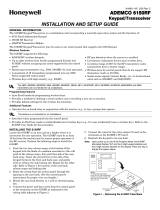
Figure 1.
Wireless System Overview using 5800RP Repeater Module
INSTALLING THE 5800RP MODULE
Mount the 5800RP remotely in its own housing following the steps
below, and avoid mounting the module with its antennas touching
a metal surface.
Check for RF Interference:
Before mounting permanently, use the
red RF Interference LED to check for strong local radio frequency
interference at the intended mounting location. If this LED is
continuously lit, the 5800RP module should be relocated.
Removing the Cover:
Remove the 5800RP's cover by inserting and
twisting a screwdriver blade in the slot at the center of the cover's
lower edge. Note that removing the cover also places the 5800RP
in the Go/No Go Test mode. This decreases its range during
installation to insure an adequate margin during normal
operation.
Mounting the Module
1.
For concealed wiring, route power wires through the
rectangular opening at the rear of the base before mounting.
For surface wiring entry, a thin breakaway area is provided
along the base's right edge.
2.
Mount the module in the selected location. For greatest
security, use all four mounting holes (two keyslot holes and
two round holes) in the plastic base.
3.
Install each antenna in the respective right-hand terminal of
the two terminal blocks at the upper edge of the 5800RP’s
circuit board, and tighten the screws to secure them.
4.
Affix the Summary of Connections label to the inside of the
module’s cover. Make sure the arrows and large ‘plus sign’ on
the label line up with the corresponding posts in the cover.
5.
If applicable, set the Site ID by referring to the Setting the
Site ID section on the next page.
Connecting the Power Supply
The 5800RP can be powered from either an AC or DC external
power source connected to terminals 1 and 2 (see figure 2).
Power source ratings are as follows:
Type Rating
AC 9VAC, 15VA (e.g., ADEMCO 1332)
DC 12VDC, 100 ma
6.
Connect the power supply to the 5800RP’s terminals. Refer to
Figure 2. These terminals are not polarized. The leads from
DC supplies may be connected to either terminal.
NOTE:
Use of power sources with higher or lower voltages may result
in damage or failure to operate properly. Non-ADEMCO power
supplies may have connectors installed. Remove the connectors prior
to attempting to connect power supply to 5800RP.
Connecting the Battery
7.
Begin battery installation by attaching an adhesive backed hook
and loop fastener strip (supplied) to the Summary of Connections
label in the cover. Place the strip within the large box drawing
labeled ‘PLACE BATTERY HERE’. Refer to Figure 2.
8.
Attach another adhesive backed hook and loop fastener strip to
the battery. Attach the battery to the cover by firmly pressing
the two hook and loop fastener strips together. Make sure the
battery is positioned as shown in Figure 2.
9.
Plug the battery cable into the battery connector on the 5800RP
PCB. Refer to Figure 2.
CHARGING NOTE:
The battery must be allowed to charge at
least 12 hours in order to reach its full capacity.
10.
Replace the cover on the 5800RP, being careful not to pinch the
battery wires between the cover and case or any PCB components.
TO
POWER
SUPPLY
TAMPER
SWITCH
MOUNTING
HOLES
(4)
BATTERY
CONNECTOR
ANTENNAS
(INSERT IN
RIGHT-HAND
TERMINALS)
WIRING
OPENING
KNOCKOUT
AREA FOR
SURFACE
WIRING
5800RP_conn-00-001-V0
POWER
TERMINALS
LIGHTS RED WHEN
SETTING SITE ID
RF INTERFERENCE
RED INDICATOR
DIP SWITCH
ON
OFF
23456781
5800RP
CIRCUIT BOARD
BATTERY
GRN YEL RED
AFFIX SUMMARY
OF CONNECTIONS
LABEL HERE
MODULE COVER
Figure 2.
5800RP Repeater Module Layout and Connections
www.PDF-Zoo.com

– 2 –
SETTING THE SITE ID
Some ADEMCO wireless devices (e.g., 5827, 5804BD) use a
programmed house ID to help avoid communication conflicts with
nearby installations. The 5800RP automatically passes all house
ID information to the appropriate receiver.
Certain newer ADEMCO wireless devices, such as the 5883 and
the 5839, use a “Site ID” instead of a House ID. The Site ID is a
factory-assigned, unique serial number built into each 5883
transceiver and must be entered into each device that uses it. The
Site ID provides many more combinations than a House ID, and
therefore is less likely to have conflicts with nearby installations.
When using the 5800RP with wireless devices that use a Site ID,
follow the steps below to enter a permanent copy of the Site ID in
the 5800RP. This procedure assumes that all such devices have
been successfully set-up and tested with the 5883, although they
may not yet be mounted in their final locations.
1.
Put the control (and the 5883) in the Go/No Go Test mode.
2.
Remove the 5800RP's cover by inserting and twisting a
screwdriver blade in the slot at the center of the cover's lower
edge. Note that removing the cover also places the 5800RP in
the Go/No Go Test mode. This decreases its range during
installation to insure an adequate margin during normal
operation.
3.
Temporarily disconnect the power supply and battery from
the 5800RP. Refer to Figure 2.
4.
Place DIP switch 1 in the ON position.
5.
Reconnect the power supply to the 5800RP. Observe that the
red LED on the 5800RP turns on and remains on. This
indicates that the 5800RP is ready to set the Site ID.
6.
Push and release the tamper switch on the 5800RP. This
causes a set-up request message to be sent to the 5883.
7.
Observe that the red LED turns off, indicating that the Site
ID has been saved in the 5800RP. If not, repeat the previous
step until it does.
NOTE:
If the tamper switch is not pushed for 1 minute or if
DIP switch 1 is turned off, the red LED turns off. This
indicates the 5800RP will no longer accept the Site ID.
8.
Place DIP switch 1 in the OFF position.
9.
Replace the cover on the 5800RP.
10.
Take the control out of the Go/No Go Test mode.
11.
If needed locate the other wireless devices in their final
locations.
12.
Test all wireless devices.
ON
23456781
MUST BE OFF
FOR NON - UL;
MUST BE ON
FOR UL
3 - 8
NOT USED
MUST BE OFF
SW-1
USED WHEN
ENROLLING
SITE ID;
OTHERWISE
MUST BE OFF
5800RP_dip-00-002-V0
Figure 3 5800RP DIP Switch
LED FUNCTIONS
LED Activates Upon
Green Normally on (lighted) when power (AC or battery) is
present. Flickering indicates RF is being processed.
Yellow Normally off. Blinks to indicate that an RF
message is being sent by the 5800RP.
Red Normally off. Turns on (lighted) when setting Site
ID. See the
Setting the Site ID
section for details.
Red
RF Interference
Lights when RF activity is present.
PROGRAMMING AND OPERATIONAL NOTES
Non-UL Installations
(DIP switch 2 must be
OFF
during normal operation)
1. Set DIP switch 2 to OFF.
2. If module supervision is desired, assign the 5800RP to a zone for
sending check-in, low battery
†
, AC loss, and RF jam messages,
and enroll its serial number. When prompted, toggle the tamper
switch to enroll the serial number. The yellow LED should blink
on when messages are sent.
Program the zone as follows:
Zone Type Input Type Loop
8
(24-hour aux)
3
(supervised RF)
1
• The 5800RP reports AC loss and RF jam conditions as “low
battery” status, which is also displayed on the control’s keypads.
This prevents either condition from causing an alarm when the
control is armed.
• The 5800RP will not repeat a message that has already been
repeated.
UL Installations
(DIP switch 2 must be
ON
during normal operation)
1.
Supervision:
Module supervision is required using the module’s
built-in serial numbers, which are enrolled in 4 zones as follows:
– Assign the first serial number to a zone for sending low
battery
†
and supervision check-in messages.
– Assign the second serial number to 3 zones for sending
tamper, AC loss, and RF jam messages.
When prompted, toggle the tamper switch to enroll the serial
numbers.
Program the zones as follows:
First Serial Number
Set DIP switch 2 to
OFF
, then enroll as follows:
Zone Zone Type Input Type Loop
Low Battery/
Check-in Zone
8
(24-hour aux)
3 - RF
(supervised RF)
1
Second Serial Number
Set DIP switch 2 to
ON
, then enroll as follows:
(keep switch 2 in the ON position when enrolling is complete)
Zone Zone Type Input Type Loop
Tamper Zone 5
(trouble by day /
alarm by night)
4 - UR
(unsupervised RF)
1
AC Loss Zone 8
(24-hour aux)
4
- UR
2
RF Jam Zone 8
(24-hour aux)
4 - UR 3
For easy identification of these messages, program alpha
descriptors at the control for each zone, using words such as
“REPEATER LOW BATTERY, REPEATER AC LOSS, etc.
† If an actual low battery condition is reported, it takes up to 12
hours after AC power is restored for the low battery restore
message to be sent (requires 12 hours for fully recharged battery).
2.
Power Supply:
Use a class 2 Listed Burglar Alarm power
supply for UL installations.
3.
Control Panel’s Current Drain Calculation:
In order to
properly choose the correct backup battery capacity for systems
using a 5800RP in UL installations, use the connected keypad’s
maximum alarm (sounder on) current rating, not the keypad’s
standby current rating, when calculating the control panel’s
total current drain. This is necessary because AC loss at the
5800RP causes the keypad to beep.
SPECIFICATIONS
Dimensions:
7-3/8" W x 4-3/8"
(10-7/8” w/antennas)
H x 1-7/16" D.
188mm W x 112mm H
(277mm w/antennas)
x 37mm D.
Input Voltage:
12VDC or 9VAC, 15VA (from separate power
supply such as ADEMCO 1332).
Current:
80mA
Battery Pack:
rechargeable, part number K0257
Range:
200ft (60m) nominal indoors from wireless devices
(the actual range to be determined with the
security system in the TEST mode).
www.PDF-Zoo.com

– 3 –
TO THE INSTALLER
Regular maintenance and inspection (at least annually) by the installer and frequent testing by the
user are vital to continuous satisfactory operation of any alarm system.
The installer should assume the responsibility of developing and offering a regular maintenance
program to the user, as well as acquainting the user with the proper operation and limitations of the
alarm system and its component parts. Recommendations must be included for a specific program
of frequent testing (at least weekly) to insure the system's operation at all times.
RADIO FREQUENCY EMISSIONS
Federal Communications Commission (FCC) Part 15
FCC ID: CFS8DL5800RP
This device complies with Part 15 of the FCC Rules. Operation is subject to the following two
conditions: (1) This device may not cause harmful interference, and (2) this device must accept any
interference received, including interference that may cause undesired operation.
Industry Canada
This Class B digital apparatus complies with Canadian ICES-003.
Cet Appareil numérique de la classe B est conforme à la norme NMB-003 du Canada.
FEDERAL COMMUNICATIONS COMMISSION (FCC) STATEMENT
This equipment has been tested to FCC requirements and has been found acceptable for use. The FCC requires the
following statement for your information:
This equipment generates and uses radio frequency energy and if not installed and used properly, that is, in strict
accordance with the manufacturer's instructions, may cause interference to radio and television reception. It has been
type tested and found to comply with the limits for a Class B computing device in accordance with the specifications in
Part 15 of FCC Rules, which are designed to provide reasonable protection against such interference in a residential
installation. However, there is no guarantee that interference will not occur in a particular installation. If this equipment
does cause interference to radio or television reception, which can be determined by turning the equipment off and on,
the user is encouraged to try to correct the interference by one or more of the following measures:
• If using an indoor antenna, have a quality outdoor antenna installed.
• Reorient the receiving antenna until interference is reduced or eliminated.
• Move the radio or television receiver away from the receiver/control.
• Move the antenna leads away from any wire runs to the receiver/control.
• Plug the receiver/control into a different outlet so that it and the radio or television receiver are on different branch
circuits.
If necessary, the user should consult the dealer or an experienced radio/television technician for additional suggestions.
The user or installer may find the following booklet prepared by the Federal Communications Commission helpful:
"Interference Handbook"
This booklet is available from the U.S. Government Printing Office, Washington, DC 20402.
The user shall not make any changes or modifications to the equipment unless authorized by the Installation
Instructions or User's Manual. Unauthorized changes or modifications could void the user's authority to operate the
equipment.
www.PDF-Zoo.com

LIMITED WARRANTY
Alarm Device Manufacturing Company, a Division of Pittway Corporation, and its divisions, subsidiaries and affiliates
("Seller"), 165 Eileen Way, Syosset, New York 11791, warrants its products to be in conformance with its own plans
and specifications and to be free from defects in materials and workmanship under normal use and service for 24
months from the date stamp control on the product or, for products not having an Ademco date stamp, for 12 months
from date of original purchase unless the installation instructions or catalog sets forth a shorter period, in which case
the shorter period shall apply. Seller's obligation shall be limited to repairing or replacing, at its option, free of charge for
materials or labor, any product which is proved not in compliance with Seller's specifications or proves defective in
materials or workmanship under normal use and service. Seller shall have no obligation under this Limited Warranty or
otherwise if the product is altered or improperly repaired or serviced by anyone other than Ademco factory service. For
warranty service, return product transportation prepaid, to Ademco Factory Service, 165 Eileen Way, Syosset, New
York 11791.
THERE ARE NO WARRANTIES, EXPRESS OR IMPLIED, OF MERCHANTABILITY, OR FITNESS FOR A
PARTICULAR PURPOSE OR OTHERWISE, WHICH EXTEND BEYOND THE DESCRIPTION ON THE FACE
HEREOF. IN NO CASE SHALL SELLER BE LIABLE TO ANYONE FOR ANY CONSEQUENTIAL OR INCIDENTAL
DAMAGES FOR BREACH OF THIS OR ANY OTHER WARRANTY, EXPRESS OR IMPLIED, OR UPON ANY OTHER
BASIS OF LIABILITY WHATSOEVER, EVEN IF THE LOSS OR DAMAGE IS CAUSED BY THE SELLER'S OWN
NEGLIGENCE OR FAULT.
Seller does not represent that the products it sells may not be compromised or circumvented; that the products will
prevent any personal injury or property loss by burglary, robbery, fire or otherwise; or that the products will in all cases
provide adequate warning or protection. Customer understands that a properly installed and maintained alarm may only
reduce the risk of a burglary, robbery, fire or other events occurring without providing an alarm, but it is not insurance or
a guarantee that such will not occur or that there will be no personal injury or property loss as a result.
CONSEQUENTLY, SELLER SHALL HAVE NO LIABILITY FOR ANY PERSONAL INJURY, PROPERTY DAMAGE OR
OTHER LOSS BASED ON A CLAIM THE PRODUCT FAILED TO GIVE WARNING. HOWEVER, IF SELLER IS HELD
LIABLE, WHETHER DIRECTLY OR INDIRECTLY, FOR ANY LOSS OR DAMAGE ARISING UNDER THIS LIMITED
WARRANTY OR OTHERWISE, REGARDLESS OF CAUSE OR ORIGIN, SELLER'S MAXIMUM LIABILITY SHALL NOT
IN ANY CASE EXCEED THE PURCHASE PRICE OF THE PRODUCT, WHICH SHALL BE THE COMPLETE AND
EXCLUSIVE REMEDY AGAINST SELLER. This warranty replaces any previous warranties and is the only warranty
made by Seller on this product. No increase or alteration, written or verbal, of the obligations of this Limited Warranty is
authorized.
165 Eileen Way, Syosset, New York 11791
Copyright © 1997 PITTWAY CORPORATION
Copyright © 2001 PITTWAY CORPORATION
¬.l
K0344 6/02
www.PDF-Zoo.com
/