Smeg HB96CSS-3 Datasheet

Category
Hobs
Type
Datasheet

Smeg HB96CSS-3 is a gas hob with four burners of different sizes and power levels, allowing you to cook a variety of dishes simultaneously. The ultra-rapid burner is perfect for boiling water or searing meat, while the auxiliary burner is ideal for simmering sauces or melting chocolate. The semi-rapid and rapid burners are versatile and can be used for a wide range of cooking tasks. The hob also features an electrical ignition system for easy lighting and flame failure safety devices for added peace of mind.

Smeg HB96CSS-3 is a gas hob with four burners of different sizes and power levels, allowing you to cook a variety of dishes simultaneously. The ultra-rapid burner is perfect for boiling water or searing meat, while the auxiliary burner is ideal for simmering sauces or melting chocolate. The semi-rapid and rapid burners are versatile and can be used for a wide range of cooking tasks. The hob also features an electrical ignition system for easy lighting and flame failure safety devices for added peace of mind.

22
Contents
INSTRUCTIONS FOR THE USER: these contain user advice, description
of the commands and the correct procedures for cleaning and maintenance
of the appliance.
INSTRUCTIONS FOR THE INSTALLER: these instructions are intended
for the qualified technician who must perform the installation, put it into
operation and test the appliance.
1. INSTRUCTIONS FOR USE ........................................................23
2. INSTRUCTIONS FOR DISPOSAL – OUR ENVIRONMENTAL
CARE ..........................................................................................24
3. SAFETY INSTRUCTIONS ..........................................................25
4. KNOW YOUR APPLIANCE ........................................................26
5. USING THE HOB........................................................................27
6. CLEANING AND MAINTENANCE..............................................29
7. INSTALLING THE APPLIANCE..................................................30
8. GAS CONNECTION ...................................................................36
9. ADAPTATION TO DIFFERENT TYPES OF GAS ......................38
10. FINAL OPERATIONS FOR GAS APPLIANCES ........................40
23
Precautions for use
1. INSTRUCTIONS FOR USE
THIS MANUAL IS AN INTEGRAL PART OF THE APPLIANCE. IT MUST BE KEPT
IN ITS ENTIRETY AND IN AN ACCESSIBLE PLACE FOR THE WHOLE
WORKING LIFE OF THE HOB.
WE URGE YOU TO READ THIS MANUAL AND ALL THE INFORMATION IT
CONTAINS CAREFULLY BEFORE USING THE APPLIANCE.
INSTALLATION MUST BE CARRIED OUT BY QUALIFIED PERSONNEL IN
ACCORDANCE WITH THE REGULATIONS IN FORCE. THIS APPLIANCE IS
INTENDED FOR DOMESTIC USES AND CONFORMS TO THE EEC
DIRECTIVES CURRENTLY IN FORCE. THE APPLIANCE HAS BEEN BUILT TO
CARRY OUT THE FOLLOWING FUNCTIONS: COOKING AND HEATING-UP OF
FOOD; ALL OTHER USES ARE CONSIDERED IMPROPER.
THE MANUFACTURER DECLINES ALL RESPONSIBILITY FOR IMPROPER
USE.
DO NOT USE THIS APPLIANCE FOR HEATING ROOMS.
DO NOT DISCARD PACKING IN THE HOME ENVIRONMENT. SEPARATE THE
VARIOUS WASTE MATERIALS AND TAKE THEM TO THE NEAREST
SELECTIVE WASTE COLLECTION CENTRE.
WHEN DISPOSING OF THE APPLIANCE IT MUST BE TAKEN TO A SELECTIVE
WASTE COLLECTION CENTRE.
DO NOT OBSTRUCT VENTILATION OPENINGS AND HEAT DISPERSAL SLITS.
THIS APPLIANCE IS DESIGNED FOR COOKING FOOD AND IT SHALL NOT BE
USED AS A SPACE HEATER.
DO NOT SPRAY AEROSOLS IN THE VICINITY OF THIS APPLIANCE WHILE IT
IS IN OPERATION.
THE IDENTIFICATION PLATE WITH THE TECHNICAL DATA, SERIAL NUMBER
AND MARK IS IN A VISIBLE POSITION UNDER THE CASING.
THE PLATE MUST NOT BE REMOVED.
24
Instructions for disposal
2. INSTRUCTIONS FOR DISPOSAL – OUR
ENVIRONMENTAL CARE
Our product's packing is made of non-polluting materials, therefore
compatible with the environment and recyclable. Please help by disposing
of the packing correctly. Find the addresses of collection, recycling and
disposal centres from your retailer or from the competent local
organisations.
Do not throw the packing or any part of it away. They can constitute a
suffocation hazard for children, especially the plastic bags.
Your old appliance also needs to be disposed of correctly.
Important: hand over your appliance to the local agency authorised for
the collection of household appliances no longer in use. Correct disposal
means intelligent recycling of valuable materials.
It is also necessary to cut the interconnecting cable to the power supply
network, removing it along with the plug.
25
Safety instructions
3. SAFETY INSTRUCTIONS
REFER TO THE INSTALLATION INSTRUCTIONS FOR THE SAFETY
REGULATIONS FOR ELECTRIC OR GAS APPLIANCES AND VENTILATION
FUNCTIONS.
IN YOUR INTERESTS AND FOR YOUR SAFETY IT HAS BEEN ESTABLISHED
BY LAW THAT THE INSTALLATION AND SERVICING OF ALL ELECTRICAL
APPLIANCES IS TO BE CARRIED OUT BY QUALIFIED PERSONNEL IN
ACCORDANCE WITH THE REGULATIONS IN FORCE.
OUR REGULAR INSTALLERS GUARANTEE A SATISFACTORY JOB.
GAS OR ELECTRIC APPLIANCES MUST ALWAYS BE DISCONNECTED BY
SUITABLY SKILLED PEOPLE.
THE PLUG TO BE CONNECTED TO THE POWER SUPPLY CABLE AND ITS
SOCKET MUST BE OF THE SAME TYPE AND CONFORM TO THE
REGULATIONS IN FORCE.
THE SOCKET MUST BE ACCESSIBLE AFTER THE APPLIANCE IS BUILT IN.
NEVER UNPLUG BY PULLING ON THE CABLE.
IT IS OBLIGATORY FOR ALL ELECTRICAL SYSTEMS TO BE GROUNDED
ACCORDING TO THE METHODS REQUIRED BY SAFETY RULES.
IMMEDIATELY AFTER INSTALLATION CARRY OUT A BRIEF INSPECTION TEST,
FOLLOWING THE INSTRUCTIONS BELOW. SHOULD THE APPLIANCE NOT
FUNCTION, DISCONNECT IT FROM THE ELECTRICITY SUPPLY AND CALL
THE NEAREST TECHNICAL ASSISTANCE CENTRE.
NEVER ATTEMPT TO REPAIR THE APPLIANCE.
THE APPLIANCE BECOMES VERY HOT DURING USE. SUITABLE HEAT-PROOF
GLOVES SHOULD BE WORN FOR ALL OPERATIONS.
THE APPLIANCE IS DESIGNED FOR USE BY ADULTS. KEEP CHILDREN AT A
SAFE DISTANCE AND NEVER ALLOW THEM TO PLAY WITH IT.
WHERE THIS APPLIANCE IS INSTALLED IN MARINE CRAFT OR IN CARAVANS,
IT SHALL NOT
BE USED AS A SPACE HEATER.
ALWAYS CHECK THAT THE CONTROL KNOBS ARE IN THE 0 (OFF) POSITION
WHEN YOU FINISH USING THE APPLIANCE.
The manufacturer declines all responsibility for damage to persons or
things caused by the non-observance of the above prescriptions or
deriving from tampering with any part of the appliance or by the use of
non-original spares.
26
Instructions for the User
4. KNOW YOUR APPLIANCE
Auxiliary Burner
(AUX)
Semi-rapid Burner
(SR)
Rapid
Burner (R)
Ultra-rapid Burner
(URP)
27
Instructions for the User
5. USING THE HOB
5.1 Gas hob
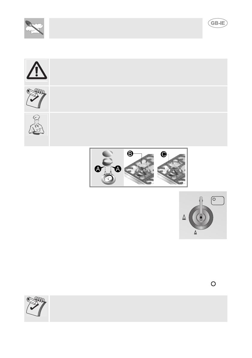
Before lighting the hob burners, check that the flame-spreader crowns are
correctly in place with their respective burner caps, making sure that the
holes A in the flame-spreaders are aligned with the plugs and
thermocouples.
Before using the electric plates or the barbecue (if included) for the first
time, pre-heat them to the maximum temperature long enough to burn off
any manufacturing oily residues which could give the food a bad smell.
The pan stand B is for use with woks. To prevent damage to the cooker
hob, it comes complete with a raised pan stand C. This must be placed
under pans with a diameter bigger than those indicated in the table in point
"5.3 Pan diameters". The pan stand C must never be used on the ultra-
rapid burner.
The burner controlled by each knob is shown next to
the knob. The appliance is equipped with an
electrical ignition device. Simply press the knob and
turn it counterclockwise to the maximum flame
symbol, until the burner lights. If it does not light in
the first 15 seconds, position the knob on 0 and wait
at least 60 seconds before trying to light it again.
On valved models, once the burner is lit, keep the knob pressed for a few
seconds to give the thermocouple time to heat up. The burner may go out
when the knob is released: in this case, the thermocouple has not heated
up sufficiently. Wait a few moments and repeat the operation keeping the
knob pressed for a longer time. This is not necessary on burners that are
not equipped with thermocouple. Once the burner is lit, the flame can be
adjusted as needed. Always check that the control knobs are in the (off)
position when you finish using the hob.
If the burners should go out accidentally, after about 20 seconds a safety
device will be tripped, cutting off the gas supply, even if the gas tap is
open. In this case, turn the knob to the OFF position and wait at least 60
seconds before trying to light the burner again.
28
Instructions for the User
5.2 Practical tips for using the burners
For better burner efficiency and to minimise gas consumption, use pans
with a flat, smooth base and a lid that have a suitable size for the burner,
thus avoiding that the flames reach the sides of the pan (see point "5.3
Pan diameters"). Once the contents come to the boil, turn down the flame
far enough to prevent the liquid from boiling over.
To prevent burns or damage to the hob during cooking, all pans or griddle
plates must be placed inside the perimeter of the hob.
Take the greatest care when using fats or oils since they may catch fire if
overheated.
5.3 Pan diameters
BURNERS
1 Auxiliary
2 Semi rapid
3Rapid
4 Ultra-rapid
MIN. AND MAX.
Ø (IN CM)
12 - 14
16 - 20
18 - 24
20 - 26
The following are the diameters of the pans that can be used with the
raised pan stand:
BURNERS
1 Auxiliary
2 Rapid
MIN. AND MAX. Ø (IN CM)
16 - 24
26 - 28
If you have the Tepanyaki plate (optional extra) never use it on the ultra-
rapid burner for any reason.
Warning:
At the end of cooking using pans with aluminium bases you may find white
residues on the cast iron pan stands. These residues are usually caused
by the pan base rubbing against the pan stand and are difficult to remove
with normal cleaning. Using abrasive or excessively aggressive products
to clean the pan stand could damage its enamel surface.
29
Instructions for the User
6. CLEANING AND MAINTENANCE
NEVER USE A JET OF STEAM FOR CLEANING THE APPLIANCE.
Before performing any operations requiring access to powered
parts, switch off the power supply to the appliance.
6.1 Cleaning stainless steel
To keep stainless steel in good condition it should be cleaned regularly
after use. Let it cool first.
6.1.1 Ordinary daily cleaning
To clean and preserve the stainless steel surfaces, use only specific
products that do not contain abrasives or chlorine-based acids.
How to use: pour the product onto a damp cloth and wipe the surface,
rinse thoroughly and dry with a soft cloth or deerskin.
6.1.2 Food stains or residues
Do not use metallic sponges or sharp scrapers: they will
damage the surface. Use ordinary non-abrasive products for
steel, with the aid of wooden or plastic utensils if necessary.
Rinse thoroughly and dry with a soft cloth or deerskin.
6.2 Cleaning the gas components
For easier cleaning the pan stands, burner caps,
flame spreader crowns and burners can all be
removed; wash them with warm water and a non-
abrasive detergent making sure to remove any
encrustation and wait until they are perfectly dry.
Replace the burner caps on their corresponding
crowns, making sure that the slots A are centred
with the burner pins B.
For correct operation the igniters and thermocouples must
always be perfectly clean. Check them frequently and clean
them with a damp cloth if necessary. Remove any dry
residues with a wooden toothpick or a needle.
30
Instructions for the installer
7. INSTALLING THE APPLIANCE
7.1 Positioning
This is a class 1 (B2) and 3 (A, B1)appliance.
The following operation requires building and/or carpentry work, therefore
it must be carried out by a skilled technician.
Installation can be carried out on various materials such as masonry,
metal, solid wood or plastic laminated wood as long as they are heat
resistant (T 90°C).
7.2 Heights for type A installation (empty base)
A
DISTANCES A B C L H
MINIMUM 866 mm 630 mm 50 mm 904 mm 750 mm
MAXIMUM 866 mm 650 mm - - -
The supporting strips must be of the appropriate size and secured
to the base in order to support the weight of the product and its use.
31
Instructions for the installer
7.3 Heights for type B installation (full base)
B
1
B
2
DISTANCES B C L H
MINIMUM 630 mm 50 mm 904 mm 750 mm
MAXIMUM 650 mm - - -
32
Instructions for the installer
7.3.1 Supporting base
Make two openings in the rear part of the base as described in the figure
below. The left opening must be used for gas connections, and the right
one for electrical connections. Before securing the hob to the supporting
base, make 4 holes 8mm in diameter at the indicated points through
which the screws will pass that are to be secured into the rivets in the
bottom part of the product.
The interaxes of the holes and the dimensions of the openings refer to a
hob installed against the back wall.
681 mm
681 mm
355 mm
189.5 mm
96 mm 200 mm
434 mm
120 mm
83.5 mm
Ø 8 mm
Ø8mm
Ø8mm
Ø8mm
109. mm5
Z
83.5 mm
33
Instructions for the installer
7.4 Mounting for type A installations
Once the hob is correctly positioned
in its support, place the brackets (A)
over the bottom part of the product
(B). Attachment requires 2 brackets
for each side of the hob.
1)
Secure the brackets to the walls of
the base by screwing the supplied
screws through the appropriate holes
(C). These operations will guarantee
that the entire product is mounted in
a stable way.
2)
Important: for fixing the product, use the supplied brackets in all the fixing
points.
34
Instructions for the installer
7.5 Mounting for type B installations
Once the hob is correctly positioned on the supporting base, complete
the mounting by tightening the product using the 4 supplied metric
screws, by screwing them through the 8mm Ø holes made before
installation. Make sure that the holes on the structure are centred with
those on the bottom of the product.
Important: other types of installation are possible if supervised by the
manufacturer.
Important: for fixing this product to the support structure, you are advised
not to use mechanical or electrical screwdrivers and to exert moderate
pressure by hand on the mounting parts.
If this product is installed over an oven, the oven must have a cooling fan.
35
Instructions for the installer
7.6 Electrical connection
Make sure that the voltage and capacity of the power line conform to the
data shown on the plate located under the casing.
Do not remove this plate for any reason.
The appliance must be connected to earth in compliance with electrical
system safety regulations.
If a fixed connection is being used, fit the power line with an omnipolar
circuit breaker with a contact opening gap equal to or greater than 3 mm,
in an easily accessible position close to the appliance.
If a plug and socket connection is being used make sure that the plug and
socket are compatible. Avoid use of adapters and shunts as these could
cause overheating and burns.
Operation at 220-240 V~: use an
H05V2V2-F type three-core cable
(3 x 0.75 mm
2
)
The end to be connected to the
appliance must be an earth wire
(yellow-green) at least 20 mm
longer.
The manufacturer declines all responsibility for damage to persons or
things caused by the non-observance of the above prescriptions or
deriving from tampering with any part of the appliance.
36
Instructions for the installer
8. GAS CONNECTION
Before installation, make sure that the local distribution conditions (nature and
pressure of the gas) and the state of regulation of the appliance are compatible.
To connect the hob to the gas supply a flexible connection
B
is required which will
enable connection to the gas inlet of the top
A
. Always place a gasket
C
between
the two connections (Fig.1) and tighten the components with a tightening torque of
at most 10 Nm.
Fig. 1
Connection to the gas supply network can be made using a
rigid copper hose
or
a
flexible steel hose
with a continuous wall and in compliance with the guidelines
established by the standard UNI-CIG 7129.
Once the operation is complete, check the hose fittings for leaks using a soapy
solution; never use a flame. The cooker hob is preset for
natural gas G20
(2H) at
a pressure of 20 mbar.
For supplying it with other types of gas, see chapter “9. ADAPTATION TO
DIFFERENT TYPES OF GAS”.
The gas inlet connection is threaded ½” external gas (ISO 228-1).
Connection with rigid copper hose:
The connection to the gas supply
network must be carried out in such a
way that it does not cause stresses of
any type on the appliance. The
connection can be made using the
adapter unit
D
with double cone, always
inserting the supplied gasket
C
in
between. Tighten the components with a
tightening torque of at most 10 Nm.
Connection with flexible steel hose:
Use only continuous wall stainless steel
hoses that comply with standard UNI-
CIG 9891, making sure to always insert
the supplied gasket
C
between the
connection
B
and the flexible hose
E
.
Tighten the components with a
tightening torque of at most 10 Nm.
Fig. 2
37
Instructions for the installer
Installation with the flexible hose must be carried out so that the length of
the piping does not exceed 2 metres fully extended; make sure that the
hoses do not come into contact with moving parts and that they are not
crushed in any way.
8.1 Connection to liquid gas
Use a pressure regulator and make the connection on the gas cylinder
following the guidelines established by the regulations in force.
Make sure that the feed pressure complies with the values indicated in the
table at point “9.2 Burner and nozzle characteristics table”.
8.2 Room ventilation
The appliance may only be installed in permanently ventilated rooms, as
specified by the standard UNI-CIG 7129 / 7131. In the room where the
appliance is installed, there must be an adequate air flow to meet the
requirements of normal combustion of gas and the necessary ventilation
of the room itself. The air vent, protected by grilles, must be suitably
dimensioned (UNI CIG 7129 / 7131) and positioned so that no part of it is
obstructed, even partially. The room must be kept adequately ventilated in
order to eliminate the heat and humidity produced by cooking: in
particular, after prolonged use, it is recommended to open a window or to
increase the speed of any ventilators.
8.3 Extraction of the products of combustion
Extraction of the products of combustion must be ensured by means of
hoods connected to a natural draught chimney whose efficiency is
assured or via forced extraction. An efficient extraction system requires
precision planning by a specialist qualified in this area and must comply
with the positions and distances indicated by the regulations. When the
job is complete, the installer must issue a certificate of conformity.
38
Instructions for the installer
9. ADAPTATION TO DIFFERENT TYPES OF GAS
Before carrying out the following operations, disconnect the appliance
from the electricity supply.
The appliance is preset for natural gas G20 (2H) at a pressure of 20
mbar. In the case of operation with other types of gas the burner nozzles
must be changed and the minimum flame adjusted on the gas taps. To
change the nozzles, proceed as described below.
9.1 Replacement of nozzles on the hob
1 Extract the pan stands and remove all the caps and flame-spreader
crowns;
2 Unscrew the burner nozzles with a 7 mm socket wrench;
3 Replace the burner nozzles according to the type of gas to be used
(see point “9.2 Burner and nozzle characteristics table“).
4 Replace the burners in the correct position.
The nozzles for using town gas (G110 – 8 mbar) are available from
authorised service centres.
39
Instructions for the installer
9.2 Burner and nozzle characteristics table
Rapid
RATED
HEATING
CAPACITY
(
KW)
LPG – G30/G31 28/37 mbar
Nozzle
diameter
1/100 mm
By-pass
1/100 mm
Reduced
capacity
(W)
Capacity
g/h G30
Capacity
g/h G31
Auxiliary (1) 1.05 50 30 400 76 75
Semi-rapid (2) 1.8 65 33 500 131 129
Rapid (3) 3 85 45 800 218 214
Ultra-rapid (4)
3.9 100 65 1600 284 279
Burner
RATED
HEATING
CAPACITY
(
KW)
NATURAL GAS – G20 20 mbar
Nozzle diameter
1/100 mm
Reduced capacity
(W)
Auxiliary (1) 1.05 72 400
Semi-rapid (2) 1.8 97 500
Rapid (3) 3 115 800
Ultra-rapid (4)
3.9 135 1600
To identify the burners on your hob, refer to the drawings in point “4.
KNOW YOUR APPLIANCE“.
40
Instructions for the installer
10. FINAL OPERATIONS FOR GAS APPLIANCES
After making the adjustments described above, reassemble the appliance
by following the instructions in point "9.1 Replacement of nozzles on the
hob" in reverse order.
After adjustment with a gas other than the preset one, replace the label on
the casing of the appliance with the label corresponding to the new gas.
This label can be obtained from the nearest Authorised Service Centre.
10.1 Adjusting the minimum for town and natural gas
Light the burner and turn it to the minimum
position. Extract the gas tap knob and turn the
adjustment screw inside or next to the tap rod
(depending on the model) until the correct
minimum flame is achieved. Refit the knob and
verify that the burner flame is stable (turning the
knob rapidly from the maximum to the minimum
position the flame must not go out). Repeat the
operation on all the gas taps.
10.2 Adjusting the minimum for liquid gas
To adjust the minimum with liquid gas, you must tighten the screw inside or
next to the tap rod (depending on the model) fully in a clockwise direction.
The bypass diameters for each individual burner are shown in the table
"9.2 Burner and nozzle characteristics table".
10.3 Lubrication of gas taps
Over time the gas taps may become difficult to turn and get blocked. Clean
them internally and replace the lubrication grease. This operation must
be carried out by a specialised technician.
  • Page 1 1
  • Page 2 2
  • Page 3 3
  • Page 4 4
  • Page 5 5
  • Page 6 6
  • Page 7 7
  • Page 8 8
  • Page 9 9
  • Page 10 10
  • Page 11 11
  • Page 12 12
  • Page 13 13
  • Page 14 14
  • Page 15 15
  • Page 16 16
  • Page 17 17
  • Page 18 18
  • Page 19 19

Smeg HB96CSS-3 Datasheet

Category
Hobs
Type
Datasheet

Smeg HB96CSS-3 is a gas hob with four burners of different sizes and power levels, allowing you to cook a variety of dishes simultaneously. The ultra-rapid burner is perfect for boiling water or searing meat, while the auxiliary burner is ideal for simmering sauces or melting chocolate. The semi-rapid and rapid burners are versatile and can be used for a wide range of cooking tasks. The hob also features an electrical ignition system for easy lighting and flame failure safety devices for added peace of mind.

Ask a question and I''ll find the answer in the document

Finding information in a document is now easier with AI