
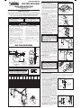
1 New Construction Vacuum Duct and Wall Inlet Valve Installation
Valve Brackets for Wall Inlet Valves
1 Locate the first valve bracket at a point the farthest
distance from the power unit. From this location,
select additional valve locations. Each location should
allow vacuuming in all corners of the room with a 30’
hose. Remember walls and furniture can shorten the
distance serviced by a valve in some areas, so be sure
to locate inlets with furniture and walls in mind.
2 Nail the valve brackets to the wall studs 12” to 15”
above the floor, usually the same distance from the
floor as electrical wall outlets. Alternate wall valve
bracket configurations are possible.
Vacuum Duct System
1 After the valve brackets are nailed in place, drill a
2‑9/16” diameter hole in the header plate directly
above each valve bracket. Cement a RISER tube from
the valve bracket, extending the tube through the hole
in the header plate for each valve.
2 Starting from the farthest valve bracket, lay tubing (cut‑
to‑length) on top of ceiling joist and work toward the
power unit location. All sweep fittings must curve
in the direction of air flow. Connect all risers from
valve brackets to the main duct line using only 90°
Sweep Tee Fittings (VM106) or 90° Sweep Fittings
(VM103). Cement all duct connections at the time
of installation. There cannot be any air leaks in the
duct systems. Testing of vacuum integrity with wall
inlet valves installed is highly recommended. Vacuum
leaks will affect system performance.
➤ NOTE: The use of nail guards (VM118) and plaster
guards (VM196) are highly recommended to protect
the wall valve brackets and vacuum duct system
during construction.
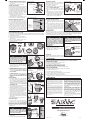
Low Voltage Vacuum Control Wiring
1 Low voltage 18‑gauge, 2‑conductor cable connects all
inlet valves to the power unit. When a hose is inserted
into the wall inlet valve, the switch in the hose activates
the power unit automatically; turning the switch off or
removing the hose stops the power unit. Low voltage
cable follows the same route as the vacuum duct
system. Route the 2‑conductor cable from each valve
bracket, up the risers to the main duct line.
2 Splice each additional riser cable to the main duct cable
using wire nuts. All connections will be in PARALLEL.
3 Secure the wiring to the horizontal main line ducts with
tape or quick clips (VM450), but DO NOT TAPE THE
CABLE TO THE RISERS. Secure the loose cable end
at each valve bracket, allowing 6” of extra cable for
each inlet valve connection and 18” of extra cable at
the power unit location.
Wall Inlet Valve Trim-out
1 When the installation is ready for trim‑out, connect the
wires from a wall inlet valve to the cable that descends
from the riser at the valve bracket.
2 Slide the wall inlet valve into the fitting on the valve
bracket.
3 Secure the wall inlet valve to the valve bracket with the
two wall plate screws.
4 Repeat steps for each wall inlet valve location.
2 Existing Construction Vacuum Duct Installation Techniques
Overhead Vacuum Duct Installation
Two people are normally required to perform overhead vacuum duct installations. Power unit installation
requirements are the same as in new construction. Wall inlet valves should be limited to interior walls. Exterior
walls contain insulation and are not normally accessible from inside the roof to drill holes for the vacuum duct.
1 After marking a wall valve location, check inside
the roof area to see if a hole can be drilled in the
header plate for the tubing. BEFORE DRILLING,
CHECK FOR ELECTRICAL WIRING. If there are no
obstructions, drill a 2‑9/16” diameter hole in the header
plate. It is possible that you will hit a fire block about
halfway down the wall. If this is the case, you must use
an extension drill and drill through the fire block. Make
sure the drill is straight up and down or you might
drill through the side of the wall!
2 After holes are drilled, lower tubing and the low‑voltage
control wire from inside the roof to the wall valve.
Seldom is the roof high enough to use a single length
of tubing. As the tube is dropped down the wall to the
valve location, several short lengths of tubing should be
cemented together with a straight coupling (VM102).
3 At the wall valve location, drill a 1” diameter hole in the
wall. Using a flashlight from the attic, check for hole
alignment. Then cut a rectangular hole 2‑½” horizontal
and 3‑½” vertically from the center of the 1” diameter
hole. This hole will allow an adapter (VM107) to make
contact with tubing inside the wall. CEMENT THE
ADAPTER TO THE TUBING.
4 Secure the adapter to the mounting bracket (VM142)
with screws. After the mounting bracket is attached to
the adapter, the completed assembly inside the wall is
ready for the inlet valve (VM195).
5 Connect the low‑voltage control wires and slide the
inlet valve into the fitting on the valve bracket. DO
NOT CEMENT THE INLET VALVE TO THE WALL
BRACKET FITTING. Tighten the valve against the
wall with screws to the mounting bracket.
CENTRAL VACUUM MODELS
AVP3000, AVP7500, AVP12000, AVP24000
AVR3000, AVR7500, AVR12000, AVR24000
INSTALLATION INSTRUCTIONS
For Platinum and Red Series AirVac Units
(for Household Use Only)
IMPORTANT SAFETY NOTES
Please read the instructions carefully! Through many years of continuous use ‑‑ and through quality tests that are
ongoing at our factory ‑‑ AirVac central vacuums, attachments and accessories have built a remarkable record
for cleaning effectiveness and safety. However, there are potential hazards that could occur if the system is not
installed and operated correctly and safely. READ ALL INSTRUCTIONS BEFORE USING THIS APPLIANCE.
THE FOLLOWING FORMATS ARE USED FOR SAFETY NOTES IN THESE INSTRUCTIONS.
IMPORTANT SAFETY INSTRUCTIONS
WARNING
TO REDUCE THE RISK OF FIRE, ELECTRICAL SHOCK, OR INJURY:
SAVE THESE INSTRUCTIONS.
PRINTER’S INSTRUCTIONS:
INSTR,INSTL,AIRVAC; LINEAR P/N: 226529 B; INK: BLACK; MATERIAL: 20# MEAD BOND; SIZE: 11.000” x 17.000”; FOLDING: 1‑FOLD VERTICAL, 1‑FOLD HORIZONTAL, FINISH 8.500” X 5.500” WITH LOGO SHOWING; SCALE: 1‑1; SIDE 1 OF 2
CAUTION
This type of warning note is used to indicate
the possibility of damage to the vacuum power
unit or vacuum duct system.
WARNING
This type of warning note is used to indicate
possible fire or electrical shock hazards that
may cause serious injuries or death.
WALL VALVE
BRACKET
VM241
WALL VALVE
BRACKET
VM241
WALL VALVE
BRACKET
VM241
WALL VALVE
BRACKET
VM241
WALL VALVE
BRACKET
VM241
VM112
VM102
VM103
VM103
VM103
VM109
DOUBLE-FLANGED
WALL TEE
VM101
VM106
VM106
VM106
LOW VOLTAGE WIRES
LOW
VOLTAGE
WIRES
LOW
VOLTAGE
WIRES
LOW VOLTAGE WIRES
AIRVAC
POWER
UNIT
VM195 WALL INLET
VALVE (BACK VIEW)
DO NOT CEMENT
THIS JOINT!
VM195 WALL INLET VALVES
TRIM OUT THE VM241 WALL
INLET VALVE BRACKETS
VM103
VM104
VM104
VM103
TYPICAL VACUUM SYSTEM INSTALLATION
IF PROPERLY
BALANCED, THE
DOOR WILL STAY AT A
HALFWAY POSITION
IF PROPERLY
BALANCED, THE
DOOR WILL STAY AT A
HALFWAY POSITION
ARCHITECT’S SPECIFICATIONS
DEPTH DIMENSIONS
(TOP VIEW)
HEIGHT DIMENSIONS
(SIDE VIEW)
WALL STUD
DRYWALL
FOR LEFTWARD EXHAUST
30"
MINIMUM
1-3/4"
16"
INTAKE
(LEFT OR
RIGHT)
EXHAUST
(LEFT, RIGHT OR VERTICAL)
40" TO
FLOOR
8-3/4"
7-1/2"
1-1/4"
INTAKE AND
EXHAUST
FROM BOTTOM
OF MOUNTING
BRACKET
EXHAUST
INTAKE
AC POWER
OUTLET MUST BE
WITHIN 5 FEET OF
POWER UNIT TOP
MAIN VACUUM TUBE
FARTHEST WALL INLET
VALVE LOCATION
POWER
UNIT
TYPICAL WALL INLET VALVE LOCATIONS
VALVE
BRACKET
DRYWALL
RISER
TUBE
STUD
VIEW FROM
INSIDE OF
WALL
VALVE BRACKET INSTALLATION
TUBING STRAP
CEILING
JOIST
90˚ ELBOW
RISER
TUBE
VALVE
BRACKET
BE SURE ALL
SWEEP TEE FITTINGS
CURVE IN THE DIRECTION
OF THE AIR FLOW
PLATE
STUD
SWEEP
TEE
MAIN VACUUM
TUBE TO
POWER UNIT
DUCT SYSTEM INSTALLATION
MAIN VACUUM
TUBE CABLE
MAIN VACUUM
TUBE
LOW
VOLTAGE
WIRES
AIRVAC
POWER UNIT
LOCATION
ROUTE 2-CONDUCTOR WIRE
FROM EACH VALVE BRACKET
UP TO THE MAIN VACUUM TUBE
CABLE THAT LEADS TO THE
POWER UNIT LOCATION
CONTROL WIRE ROUTING
VM450
QUICK
CLIP
VM450
QUICK
CLIP
WIRE
NUTS
SPLICE WIRES
IN
PARALLEL
FROM VALVE
BRACKET
DO NOT TAPE
CABLE TO RISER!
CONTROL WIRE SPLICING
CONNECT CONTROL
WIRES TO WALL
INLET VALVE
ATTACH WALL INLET
VALVE TO VALVE
BRACKET WITH
TWO SCREWS
DO NOT CEMENT
THIS CONNECTION!
WALL INLET VALVE TRIM-OUT
LOWER RISER
TUBE DOWN
FROM ATTIC
BECAUSE OF LOW
ATTIC CLEARANCE
USE VM102 COUPLINGS
TO CONNECT SEVERAL
SHORT LENGHTS OF
TUBING
1“ DIAMETER
WALL INLET VALVE
INSPECTION HOLE
RISER TUBE
OVERHEAD RISER INSTALLATION
CUT HOLE 2-1/2” WIDE BY
3-1/2” HIGH TO SLIP VM107
ADAPTER INSIDE WALL
VM107
ADAPTER
LOW VOLTAGE
CONTROL WIRE
(DO NOT TAPE TO RISER!)
ALIGN WITH
FINGER WHILE
CEMENTING THE
FITTING TO THE
RISER TUBE
ALIGNING THE WALL ADAPTER FITTING
CAUTION
All wiring installation must conform to local
electrical codes. Wiring in the ground (soil)
must be in conduit. All wiring installation must
have a good, solid mechanical connection.
Protect all connections and/or splices against
short circuits using wire nuts.
CAUTION
DO NOT CEMENT WALL INLET VALVES TO THE
VALVE BRACKET FITTING! Occasionally, wall
inlet valves require replacement due to leaky
gaskets or other damage. If the wall inlet valve
is cemented to the valve bracket fitting, the
wall inlet valve cannot be replaced.
1 NEVER OPERATE THE SYSTEM ON WET
SURFACES OR TO PICK UP LIQUIDS.
2 DO NOT USE THE SYSTEM TO VACUUM UP
FLAMMABLE OR COMBUSTIBLE LIQUIDS
SUCH AS GASOLINE or use in areas where they
may be present.
3 Connect the power unit to a properly grounded
AC outlet only on a dedicated branch circuit.
4 Current‑carrying vacuum hose contains electrical
wires. DO NOT USE THE HOSE IF IT IS
DAMAGED, CUT, OR PUNCTURED. Avoid
vacuuming up sharp objects with the hose.
5 The AirVac system is not a toy. NEVER LET
CHILDREN OPERATE, OR PLAY WITH THE
AIRVAC SYSTEM.
6 Use only as described in the Owner’s Manual and
only with the manufacturer’s recommended
attachments.
7 Do not vacuum up anything that is burning or
smoking, such as cigarettes, matches, or hot
ashes.
8 Do not use without the dust bag (Platinum Series
only) and filters in place.
9 Keep hair, loose clothing, fingers, and all parts of
the body away from openings and moving parts.
10 Do not put any object into any of the wall inlet
valves or vacuum auxiliary air inlet. Do not use
the system with any vacuum opening blocked;
keep all ducting free of dust, lint, hair, or anything
that may reduce the air flow.
11 Turn off all controls before unplugging the power
unit.
12 Use extra care when cleaning stairs to prevent a
fall.
IF PROPERLY
BALANCED, THE
DOOR WILL STAY AT A
HALFWAY POSITION
SPECIFICATIONS
POWER UNIT SPECIFICATIONS
AIRVAC
MODEL
OPERATING
VOLTAGE
OPERATING
CURRENT
HOUSE
CIRCUIT
BREAKER
SIZE
RECEPTACLE
TYPE
HOME
SQUARE
FOOTAGE
MAXIMUM
DUCT
LENGTH
DEBRIS
CAPACITY
AIR
WATTS
WATER
LIFT
AIR
FLOW
AVR3000 120 VAC 13.5 AMPS 20 AMP TYPE 1 3000 150 FEET 6 GALLONS 537 PEAK 123” 118 CFM
AVR7500 120 VAC 13.5 AMPS 20 AMP TYPE 1 7500 200 FEET 6 GALLONS 551 PEAK 131” 118 CFM
AVR12000 120 VAC 13.5 AMPS 20 AMP TYPE 1 12000 350 FEET 6 GALLONS 570 PEAK 127” 122 CFM
AVR24000 240 VAC 7 AMPS 15 AMP TYPE 2 12000 500 FEET 6 GALLONS 627 PEAK 137” 124 CFM
AVP3000 120 VAC 13.5 AMPS 20 AMP TYPE 1 3000 150 FEET 5.2 GALLONS 537 PEAK 123” 118 CFM
AVP7500 120 VAC 13.5 AMPS 20 AMP TYPE 1 7500 200 FEET 5.2 GALLONS 551 PEAK 131” 118 CFM
AVP12000 120 VAC 13.5 AMPS 20 AMP TYPE 1 12000 350 FEET 5.2 GALLONS 570 PEAK 127” 122 CFM
AVP24000 240 VAC 7 AMPS 15 AMP TYPE 2 12000 500 FEET 5.2 GALLONS 627 PEAK 137” 124 CFM
CAUTION
All circuit breakers must be SEPARATE and DEDICATED
as with any other major appliance. The electrical outlets
MUST match the plug WITHOUT USE OF ADAPTERS
120 VAC
NEMA 5-15R
240 VAC
NEMA 6-15R
RECEPTACLE
TYPES
“TYPE 1”
“TYPE 2”

Vacuum Intake Connection
Depending on the requirements of the installation, the
main vacuum duct line can be connected to the left or
right side intake port of the power unit.
1 Cut a 4" piece of duct tubing.
2 Slide the tubing piece into the left or right power unit
intake port. DO NOT CEMENT TUBING.
3 Slide a hose clamp onto the flexible hose. Slide the
flexible hose onto the tubing piece. Tighten the hose
clamp.
4 Slide another hose clamp onto the flexible hose.
Connect the flexible hose to the drop from the main
vacuum duct system line. Tighten the hose clamp.
5 The unused power unit intake port MUST be sealed,
slide the inlet plug onto the unused intake port.
4 Power Unit Electrical
Low Voltage Control Wire Connection
1 Strip back the insulation about 1/2" from the two‑
conductor low voltage control wire cable at the power
unit.
2 Using a small screwdriver or other object, press down
on one of the wire locks on the control wire connector
(top rear of motor head) while inserting the wire
into the connector hole. Release the wire lock while
holding the wire in. Repeat with the other wire and the
other hole. Polarity is not important, either wire can be
connected to either hole.
Grounding Instructions
This appliance must be grounded. If it should malfunction or breakdown, grounding provides a path of least
resistance for electrical current to reduce the risk of electrical shock. This appliance is equipped with a cord having
an equipment‑grounding conductor and grounding plug. The plug must be plugged into an appropriate outlet that
is properly installed and grounded in accordance with all local codes and ordinances.
Power Connection
1 BE SURE THE UNIT’S POWER SWITCH IS OFF.
Plug the line cord into the AC receptacle.
2 Verify that power is available to the vacuum by
switching the unit’s power on then off.
System Testing
The AirVac central vacuum system should be tested for good suction throughout the system. Use a vacuum gauge
(VM181) at each wall inlet valve location to measure the vacuum suction.
5 Troubleshooting
NOTE: NO USER SERVICEABLE PARTS INSIDE, DO NOT LUBRICATE MOTOR.
IF THE MOTOR FAILS TO OPERATE
1 Be sure the power unit is plugged into a working AC outlet.
2 Push breaker reset button on the power unit.
3 Check the panel circuit breaker that connects the power unit.
AFTER CHANGING OF THE BAG (PLATINUM SERIES ONLY)
1 Push down the RESET button for 7 seconds to reset the bag indicator.
IN CASE OF LOW VACUUM POWER
1 Be sure that the inlet plug is inserted into the unused power unit intake port.
2 Check that all wall valves are closed.
3 Check that all gaskets on wall valves are sealed.
4 Check to see if debris bucket or bag (Platinum Series only) needs emptying.
5 Check for obstructions in the hose, tools, or vacuum lines.
6 Check for any ruptures or breaks in the vacuum duct system.
If you are unable to resolve the operational problems, please contact AirVac technical support at (800) 421‑1587.
6 Limited Warranty
Overhead Vacuum Duct Installation (continued)
6 Secure the inlet valve to the valve bracket with the two
wall plate screws.
7 Repeat steps for each wall inlet valve location.
Under the Floor Installation
In homes with a pier and beam foundation or basement,
either the overhead or an under the floor installation can
be made. Sometimes under the floor installation is easier
in an existing home, especially if the roof has a low pitch
and clearances in the attic adds to the installation problem.
Under the floor installation also eliminates encountering
fire blocks in the wall. Shorter risers are also utilized,
eliminating the longer tube drop from the attic.
1 Vacuum tubing should be secured to floor joist with
perforated nailing strips or tube straps.
2 Generally, follow the overhead installation steps, but
from below the floor, to install each wall inlet valve.
Alternate Vacuum Duct Riser Installation
An effective technique highly suitable for many types
of construction with adequate working room inside the
attic is to make drops to the wall inlet valves through the
ceiling, then route the tube through the wall at inlet level
for the inlet valve on the opposite side of the wall. If this
method is used, the drop from the inside of the attic for the
riser can be made in the corner of a closet, utility room,
etc. where the tubing is not visible or not objectionable
to the Homeowner. On occasion this might be the only
alternative for placing an inlet valve in a desired location.
3 Power Unit Installation
Power Unit Unpacking and Pre-assembly
This AirVac power unit is packaged disassembled in a nested configuration which reduces the size of the shipping
carton and allows for much smaller shelf space requirements than previous AirVac models. The power unit must
be assembled during installation.
1 Carefully remove the nested vacuum from the box.
2 Separate each of the nested parts and place them
gently on the floor.
3 Refer to the parts identification figure below to
familiarize yourself with each of the parts.
4 Connect the 90° steel exhaust elbow to the motor
head. The exhaust elbow can point to the left, right or
vertical depending on the installation requirements.
Secure the exhaust elbow to the motor head flange
with the #4 self‑tapping screw.
5 PLATINUM SERIES ONLY: Install the dust cone inside
the bottom end of the vacuum body as shown in the
figure. Be sure the cone snaps against the large ridge in
the vacuum body. DO NOT PUSH DUST CONE PAST
THE LARGE RIDGE!
6 PLATINUM SERIES ONLY: Install the slide‑gate collar
dust bag into the debris bucket. BE SURE TO FULLY
EXPAND THE BAG WITH YOUR HAND TO FILL THE
BUCKET.
Power Unit Mounting
1 Determine the mounting location for the power unit. Be
sure clearance dimensions are followed. The power
supply cord length is 5 feet. An AC power outlet of the
proper type on a dedicated circuit breaker must be
available within 5 feet so the power supply cord can be
directly plugged into the electrical outlet. DO NOT USE
AN EXTENSION CORD.
2 Use a stud finder to locate a wall stud for attaching the
mounting bracket. Mark the stud location.
3 Attach the mounting bracket to the wall, centered on the
marked stud, with the bottom edge 40" above the floor,
using the two 1/4" x 2" lag screws and a 7/16" socket.
4 Carefully hang the vacuum body by sliding the body’s
mounting tab into the mounting bracket slot.
5 Fit the motor head onto the vacuum body with the
controls facing forward latching the two locking snaps.
6 Hang the debris bucket on the two bucket slide latches.
Swing the two slide latch handles up to lock the debris
bucket into place.
7 Slide the exhaust muffler onto the exhaust elbow.
Optional Exhaust Tubing
The vacuum’s exhaust can be piped away from the
power unit if desired or required. The exhaust tubing
must vent to the outside of the house, NOT INTO THE
ATTIC. A louvered exhaust vent cap (VM136) is available
to terminate the exhaust tubing. Steel tubing is also
available for the exhaust tubing and may be required by
local building codes.
1 Install any optional exhaust tubing following the
guidance above.
2 Connect the optional exhaust tubing to the muffler.
Copyright © 2010 Linear LLC 226529 B
PRINTER’S INSTRUCTIONS:
INSTR,INSTL,AIRVAC; LINEAR P/N: 226529 B; INK: BLACK; MATERIAL: 20# MEAD BOND; SIZE: 11.000” x 17.000”; FOLDING: 1‑FOLD VERTICAL, 1‑FOLD HORIZONTAL, FINISH 8.500” X 5.500” WITH LOGO SHOWING; SCALE: 1‑1; SIDE 2 OF 2
THE TUBING DROP
CAN BE INSIDE A CLOSET
THEN THROUGH THE
WALL TO THE WALL
VALVE INSIDE THE ROOM
RISER AND
CONTROL
WIRE
TO WALL VALVE
ON OTHER SIDE
OF THE WALL
HOLE IN
CEILING
ALTERNATE DUCT RISER INSTALLATION
CAUTION
Do not mount the motor head onto the vacuum
body until AFTER the vacuum body is hung on
the mounting bracket. Placing the motor head
on the vacuum body before mounting causes
the unit to be top heavy and may tip the vacuum
over, causing damage to the vacuum.
VACUUM BODY
EXHAUST MUFFLER
EXHAUST ELBOW
INLET PLUG
MOUNTING
BRACKET
LAG
SCREWS
HOSE
CLAMPS
FLEXIBLE HOSE
SLIDE-GATE COLLAR BAG
(PLATINUM SERIES ONLY)
DUST CONE
(PLATINUM SERIES ONLY)
DEBRIS BUCKET
MOTOR HEAD
VACUUM PARTS IDENTIFICATION
SNAP MOTOR HEAD
ONTO VACUUM BODY
RETAINING
SNAP
HANG DEBRIS
BUCKET ON BUCKET
SLIDE LATCHES
BUCKET
SLIDE
LATCH
SWING THE TWO
BUCKET SLIDE
LATCHES UP
INSTALLING THE MOTOR HEAD AND DEBRIS BUCKET
ATTACH MOUNTING BRACKET
TO WALL WITH TWO LAG SCREWS
BOTTOM
EDGE 40"
ABOVE
FLOOR
HANG VACUUM BODY ON
MOUNTING BRACKET
SCREW TO
WALL STUD
HANGING THE MOUNTING BRACKET & MOUNTING THE VACUUM BODY
CAUTION
In order to avoid motor failure resulting from
excessive back pressure, DO NOT install more
than 30 feet of exhaust tubing and DO NOT
install any bends in the exhaust tubing closer
than 18" from the exhaust muffler.
EXPAND THE DUST
BAG BEFORE PLACING
IT INTO THE DEBRIS BUCKET
SLIDE-GATE COLLAR BAG
PLACE THE BAG INTO THE
DEBRIS BUCKET AND
EXPAND THE BAG AGAINST
THE DEBRIS BUCKET SIDES
PLACE BAG'S
SLIDE-GATE
HERE
DUST BAG INSTALLATION (PLATINUM SERIES ONLY)
18" MINIMUM FROM
THE MUFFLER BEFORE
ANY BENDS IN THE
EXHAUST TUBING
VM136
LOUVERED
EXHAUST
VENT CAP
OUTSIDE
WALL
EXHAUST TUBING
MUST VENT OUTSIDE
OF THE HOUSE
OPTIONAL EXHAUST TUBING
FLEXIBLE
HOSE
HOSE
CLAMPS
MAIN
VACUUM
TUBE
INSERT THE INLET
PLUG ONTO THE
UNUSED VACUUM
INTAKE PORT
VACUUM
INTAKE PORT
THE UNUSED
INTAKE PORT
MUST BE SEALED!
VACUUM INTAKE CONNECTION
PUSH EACH WIRE
LOCK DOWN WHILE
INSERTING THE WIRE
INTO THE CONECTOR
HOLE
LOW VOLTAGE
CONTROL WIRE
FROM WALL VALVES
LOW VOLTAGE
CONTROL WIRE
CONNECTOR
LOW VOLTAGE CONTROL WIRE CONNECTION
USA & Canada (800) 421-1587 & (800) 392-0123
(760) 438-7000 - Toll Free FAX (800) 468-1340
www.linearcorp.com
WARNING
Improper connection of the equipment-grounding
conductor can result in risk of electric shock.
Check with a qualified electrician or service
person if you are in doubt as to whether the
outlet is properly grounded. Do not modify the
plug provided with the appliance - if it will not
fit the outlet, have a proper outlet installed by a
qualified electrician.
CAUTION
All circuit breakers must be SEPARATE and
DEDICATED as with any other major appliance.
The electrical outlets MUST match the plug
WITHOUT THE USE OF ADAPTERS. DO NOT USE
AN EXTENSION CORD.
PLUG THE POWER UNIT
INTO A
GROUNDED
AC OUTLET THAT IS
WIRED TO A DEDICATED
CIRCUIT BREAKER
DO NOT USE AN
EXTENSION CORD
OR AN AC ADAPTER!
BE SURE THE POWER
SWITCH IS OFF
AC POWER CONNECTION
PLATE
FLOOR
INSTALL
VALVE BRACKET
12" TO 15" ABOVE
FLOOR LEVEL
FLOOR
JOIST
VM106
SWEEP TEE
STUD
MAIN VACUUM TUBE
FLOW
UNDER FLOOR INSTALLATION
Linear LLC warrants AirVac Platinum Series power units to be free of defects for
10 years, and AirVac Red Series power units to be free of defects for 5 years.
The warranty period begins from either (1) the date of “first user” purchase of
this product or (2) the first close of escrow date on a residence in which this
new product was originally installed. This warranty extends to the original user
of the product and to each subsequent owner of the product during the term of
this warranty. Linear LLC will repair or replace, at its option, parts and materials
at no charge. Parts supplied under this warranty may be new or rebuilt at the
option of Linear LLC.
If, during the limited warranty period, it appears as though this product contains
a defect which is covered by this limited warranty, call our toll free service
number before dismantling the product (1-800-421-1587). Remember to
attain a Return Product Authorization number (RPA) before returning any
product to Linear LLC. Send this product freight pre-paid and insured
to our service center for warranty repair. You will be advised on shipping
instructions when you call the toll free service number. Linear LLC will return
the repaired product freight pre‑paid within the U.S.A. The installing dealer or
distributor may assist you, at your choice and expense, with returning product
for repair. Please include a brief description of the problem and a dated proof‑
of‑purchase receipt with any product that is returned for warranty repair. ANY
PRODUCT RETURNED WITHOUT A RETURN PRODUCT AUTHORIZATION
NUMBER WILL BE REFUSED.
THIS LIMITED WARRANTY IS IN LIEU OF ANY OTHER WARRANTIES,
EXPRESS OR IMPLIED, INCLUDING ANY IMPLIED WARRANTY OF
MERCHANTABILITY OR FITNESS FOR A PARTICULAR PURPOSE OR
OTHERWISE, AND OF ANY OTHER OBLIGATIONS OR LIABILITY ON THE
SELLER’S PART. THIS LIMITED WARRANTY DOES NOT COVER DAMAGE
CAUSED BY ACTS OF GOD, IMPROPER INSTALLATION, NORMAL
SYSTEM WEAR AND TEAR AS DEFINED BY THE MANUFACTURER, THE
VIOLATION OF APPLICABLE BUILDING OR ELECTRICAL CODES, OR
THE USE OF NON-AIRVAC WIRE, CABLE, OR WALL HOUSINGS. THIS
LIMITED WARRANTY APPLIES ONLY TO PRODUCTS INSTALLED IN A
PRIVATE RESIDENCE.
UNDER NO CIRCUMSTANCES SHALL THE SELLER BE LIABLE FOR
CONSEQUENTIAL, INCIDENTAL OR SPECIAL DAMAGES ARISING IN
CONNECTION WITH USE, OR INABILITY TO USE THIS PRODUCT. IN
NO EVENT SHALL SELLER’S LIABILITY, FOR BREACH OF WARRANTY,
BREACH OF CONTRACT, NEGLIGENCE, OR STRICT LIABILITY, EXCEED
THE COST OF THE PRODUCT COVERED HEREBY. NO PERSON
IS AUTHORIZED TO ASSUME FOR US ANY OTHER LIABILITY IN
CONNECTION WITH THE SALE OF THIS PRODUCT.
Some states do not allow the exclusion or limitation of consequential, incidental
or special damages, so the above limitation or exclusion may not apply to you.
This limited warranty gives you specific legal rights, and you may also have
other rights which vary from state to state.
ATTACH THE EXHAUST
ELBOW TO THE MOTOR
HEAD WITH #4 SCREW
EXHAUST ELBOW
CAN POINT TO
LEFT, RIGHT OR VERTICAL
TIP DUST CONE
INTO VACUUM BODY
BOTTOM END
PRESS DUST CONE
IN UNTIL THE FOUR
TABS SNAP AGAINST
THE LARGE RIDGE
DO NOT PRESS
CONE PAST THE
LARGE RIDGE
EXHAUST ELBOW & DUST CONE INSTALLATION
www.purelypowerful.com
Manufactured by:
-
 1
1
-
 2
2


AirVac AVP3000 Installation guide
- Type
- Installation guide
Ask a question and I''ll find the answer in the document
Finding information in a document is now easier with AI
Related papers

Other documents
-
Linear Central Vacuum User manual
-
Philips DC910/05 Quick Setup Guide
-
 AC-Safe PAC-6H Operating instructions
-
 NPS SGRTP4 Owner's manual
-
NuTone CV570 User manual
-
-
Channel Plus CHANNELPLUS SVD-8 User manual
-
-
Nortek Contol CHANNEL PLUS 5445 User manual
-
Matco Tools AirVAC Handheld Shop Vacuum Operating instructions

