Garmin G1000 - Socata TBM 850 Reference guide
- Category
- Car navigation systems
- Type
- Reference guide
This manual is also suitable for

Socata
TBM 850

Garmin G1000 Pilot’s Guide for the Socata TBM 850
190-00709-00 Rev. A
Copyright © 2007 Garmin Ltd. or its subsidiaries. All rights reserved.
This manual reflects the operation of System Software version 0719.00 or later for the Socata TBM 850. Some differences in operation may
be observed when comparing the information in this manual to earlier or later software versions.
Garmin International, Inc., 1200 East 151st Street, Olathe, Kansas 66062, U.S.A.
Tel: 913/397.8200 Fax: 913/397.8282
Garmin AT, Inc., 2345 Turner Road SE, Salem, OR 97302, U.S.A.
Tel: 503/391.3411 Fax 503/364.2138
Garmin (Europe) Ltd, Liberty House, Bulls Copse Road, Hounsdown Business Park, Southampton, SO40 9RB, U.K.
Tel: 44/0870.8501241 Fax: 44/0870.8501251
Garmin Corporation, No. 68, Jangshu 2nd Road, Shijr, Taipei County, Taiwan
Tel: 886/02.2642.9199 Fax: 886/02.2642.9099
Web Site Address: www.garmin.com
Except as expressly provided herein, no part of this manual may be reproduced, copied, transmitted, disseminated, downloaded or stored
in any storage medium, for any purpose without the express written permission of Garmin. Garmin hereby grants permission to download
a single copy of this manual and of any revision to this manual onto a hard drive or other electronic storage medium to be viewed for
personal use, provided that such electronic or printed copy of this manual or revision must contain the complete text of this copyright notice
and provided further that any unauthorized commercial distribution of this manual or any revision hereto is strictly prohibited.
Garmin
®
and G1000
®
are registered trademarks of Garmin Ltd. or its subsidiaries. FliteCharts™, and SafeTaxi™ are trademarks of Garmin
Ltd. or its subsidiaries. These trademarks may not be used without the express permission of Garmin.
NavData
®
is a registered trademark of Jeppesen, Inc.; Stormscope
®
is a registered trademark of L-3 Communications; and XM
®
is a
registered trademark of XM Satellite Radio, Inc.; Honeywell
®
and Bendix/King
®
are registered trademarks of Honeywell International,
Inc.; Becker
®
is a registered trademark of Becker Flugfunkwerk GmbH.
November, 2007 Printed in the U.S.A

190-00709-00 Rev. A
Garmin G1000 Pilot’s Guide for the Socata TBM 850
i
LIMITED WARRANTY
LIMITED WARRANTY
This Garmin product is warranted to be free from defects in materials or workmanship for two years from the date of purchase. Within this
period, Garmin will, at its sole option, repair or replace any components that fail in normal use. Such repairs or replacement will be made
at no charge to the customer for parts and labor, provided that the customer shall be responsible for any transportation cost. This warranty
does not cover failures due to abuse, misuse, accident, or unauthorized alterations or repairs.
THE WARRANTIES AND REMEDIES CONTAINED HEREIN ARE EXCLUSIVE AND IN LIEU OF ALL OTHER WARRANTIES EXPRESS OR IMPLIED
OR STATUTORY, INCLUDING ANY LIABILITY ARISING UNDER ANY WARRANTY OF MERCHANTABILITY OR FITNESS FOR A PARTICULAR
PURPOSE, STATUTORY OR OTHERWISE. THIS WARRANTY GIVES YOU SPECIFIC LEGAL RIGHTS, WHICH MAY VARY FROM STATE TO
STATE.
IN NO EVENT SHALL GARMIN BE LIABLE FOR ANY INCIDENTAL, SPECIAL, INDIRECT OR CONSEQUENTIAL DAMAGES, WHETHER
RESULTING FROM THE USE, MISUSE, OR INABILITY TO USE THIS PRODUCT OR FROM DEFECTS IN THE PRODUCT. Some states do not
allow the exclusion of incidental or consequential damages, so the above limitations may not apply to you.
Garmin retains the exclusive right to repair or replace the unit or software, or to offer a full refund of the purchase price, at its sole
discretion. SUCH REMEDY SHALL BE YOUR SOLE AND EXCLUSIVE REMEDY FOR ANY BREACH OF WARRANTY.
To obtain warranty service, contact your local Garmin Authorized Service Center. For assistance in locating a Service Center near you, visit
the Garmin Web site at “http://www.garmin.com” or contact Garmin Customer Service at 800-800-1020.

Garmin G1000 Pilot’s Guide for the Socata TBM 850
190-00709-00 Rev. Aii
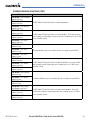
WARNINGS, CAUTIONS, AND NOTES
WARNING: Navigation and terrain separation must NOT be predicated upon the use of the terrain function.
The G1000 Terrain Proximity feature is NOT intended to be used as a primary reference for terrain avoidance
and does not relieve the pilot from the responsibility of being aware of surroundings during flight. The
Terrain Proximity feature is only to be used as an aid for terrain avoidance and is not certified for use
in applications requiring a certified terrain awareness system. Terrain data is obtained from third party
sources. Garmin is not able to independently verify the accuracy of the terrain data.
WARNING: The displayed minimum safe altitudes (MSAs) are only advisory in nature and should not be
relied upon as the sole source of obstacle and terrain avoidance information. Always refer to current
aeronautical charts for appropriate minimum clearance altitudes.
WARNING: The Garmin G1000 has a very high degree of functional integrity. However, the pilot must
recognize that providing monitoring and/or self-test capability for all conceivable system failures is not
practical. Although unlikely, it may be possible for erroneous operation to occur without a fault indication
shown by the G1000. It is thus the responsibility of the pilot to detect such an occurrence by means of
cross-checking with all redundant or correlated information available in the cockpit.
WARNING: For safety reasons, G1000 operational procedures must be learned on the ground.
WARNING: The altitude calculated by G1000 GPS receivers is geometric height above Mean Sea Level and
could vary significantly from the altitude displayed by pressure altimeters, such as the GDC 74A Air Data
Computer, or other altimeters in aircraft. GPS altitude should never be used for vertical navigation. Always
use pressure altitude displayed by the G1000 PFD or other pressure altimeters in aircraft.
WARNING: Do not use outdated database information. Databases used in the G1000 system must be
updated regularly in order to ensure that the information remains current. Pilots using any outdated
database do so entirely at their own risk.
WARNING: Do not use basemap (land and water data) information for primary navigation. Basemap data is
intended only to supplement other approved navigation data sources and should be considered as an aid to
enhance situational awareness.
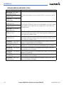
WARNING:
Lamp(s) inside this product may contain mercury (HG) and must be recycled or disposed of
according to local, state, or federal laws. For more information, refer to our website at www.garmin.com/
aboutGarmin/environment/disposal.jsp.
WARNING
:
Because of anomalies in the earth’s magnetic field, operating the G1000 within the following
areas could result in loss of reliable attitude and heading indications. North of 70° North latitude and south
of 70° South latitude. An area north of 65° North latitude between longitude 75º West and 120º West. An
area south of 55° South latitude between longitude 120º East and 165º East.
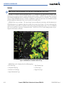
CAUTION: The illustrations in this guide are only examples. Never use the G1000 to attempt to penetrate
a thunderstorm. Both the FAA Advisory Circular, Subject: Thunderstorms, and the
Aeronautical
Information
Manual (AIM) recommend avoiding “by at least 20 miles any thunderstorm identified as severe or giving an
intense radar echo.”

190-00709-00 Rev. A
Garmin G1000 Pilot’s Guide for the Socata TBM 850
iii
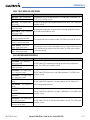
WARNINGS, CAUTIONS, AND NOTES
CAUTION: The United States government operates the Global Positioning System and is solely responsible
for its accuracy and maintenance. The GPS system is subject to changes which could affect the accuracy
and performance of all GPS equipment. Portions of the Garmin G1000 utilize GPS as a precision electronic
NAVigation AID (NAVAID). Therefore, as with all NAVAIDs, information presented by the G1000 can be
misused or misinterpreted and, therefore, become unsafe.
CAUTION: To reduce the risk of unsafe operation, carefully review and understand all aspects of the
G1000 Pilot’s Guide documentation. Thoroughly practice basic operation prior to actual use. During flight
operations, carefully compare indications from the G1000 to all available navigation sources, including
the information from other NAVAIDs, visual sightings, charts, etc. For safety purposes, always resolve any
discrepancies before continuing navigation.
CAUTION: The Garmin G1000 does not contain any user-serviceable parts. Repairs should only be made by
an authorized Garmin service center. Unauthorized repairs or modifications could void both the warranty
and the pilot’s authority to operate this device under FAA/FCC regulations.
CAUTION: The PFD and MFD displays use a lens coated with a special anti-reflective coating that is very
sensitive to skin oils, waxes, and abrasive cleaners. CLEANERS CONTAINING AMMONIA WILL HARM THE
ANTI-REFLECTIVE COATING. It is very important to clean the lens using a clean, lint-free cloth and an
eyeglass lens cleaner that is specified as safe for anti-reflective coatings.
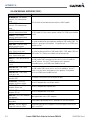
NOTE: All visual depictions contained within this document, including screen images of the G1000 panel and
displays, are subject to change and may not reflect the most current G1000 system and aviation databases.
Depictions of equipment may differ slightly from the actual equipment.
NOTE: This device complies with part 15 of the FCC Rules. Operation is subject to the following two conditions:
(1) this device may not cause harmful interference, and (2) this device must accept any interference received,
including interference that may cause undesired operation.
NOTE: There are several atmospheric phenomena in addition to nearby thunderstorms that can cause
isolated discharge points in the strike display mode. However, clusters of two or more discharge points in
the strike display mode do indicate thunderstorm activity if these points reappear after the screen has been
cleared. Avoid the clusters to avoid the thunderstorms. In the cell display mode, even a single discharge
point may represent thunderstorm activity and should therefore be avoided.
NOTE
: Interference from GPS repeaters operating inside nearby hangars can cause an intermittent loss of
attitude and heading displays while the aircraft is on the ground. Moving the aircraft more than 100 yards
away from the source of the interference should alleviate the condition.
NOTE
: Use of polarized eyewear may cause the flight displays to appear dim or blank.
NOTE
: This product, its packaging, and its components contain chemicals known to the State of California
to cause cancer, birth defects, or reproductive harm. This notice is being provided in accordance with
California’s Proposition 65. If you have any questions or would like additional information, please refer to
our web site at www.garmin.com/prop65.

Garmin G1000 Pilot’s Guide for the Socata TBM 850
190-00709-00 Rev. Aiv
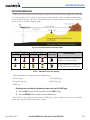
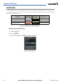
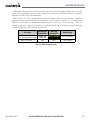
REVISION INFORMATION
Record of Revisions
Part Number
Revision Date Page Range Description
190-00709-00 A 11/2/07 All Initial Release

190-00709-00 Rev. A
Garmin G1000 Pilot’s Guide for the Socata TBM 850
v
TABLE OF CONTENTS
SECTION 1 SYSTEM OVERVIEW
1.1 System Description ..............................................1-1
1.2 Line Replaceable Units (LRU) ..............................1-2
1.3 G1000 Controls .....................................................1-7
PFD Controls .............................................................1-7
Controls Associated With the MFD ..............................1-9
AFCS Controls .........................................................1-10
Audio Panel Controls ...............................................1-12
1.4 Secure Digital Cards ..........................................1-14
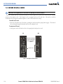
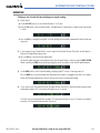
1.5 System Power-up ................................................1-15
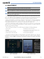
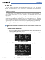
1.6 System Operation ...............................................1-16
Normal Operation ....................................................1-16
Reversionary Mode ..................................................1-16
G1000 System Annunciations ...................................1-19
Softkey Function ......................................................1-20
GPS Receiver Operation ...........................................1-25
1.7 Accessing G1000 Functionality ........................1-29
Menus ....................................................................1-29
MFD Page Groups ....................................................1-30
MFD System Pages ..................................................1-34
1.8 Display Backlighting ..........................................1-42
Automatic Adjustment .............................................1-42
Manual Adjustment .................................................1-42
SECTION 2 FLIGHT INSTRUMENTS
2.1 Flight Instruments ................................................2-4
Airspeed Indicator .....................................................2-4
Attitude Indicator ......................................................2-6
Altimeter ..................................................................2-8
Radar Altimeter .......................................................2-11
Vertical Speed Indicator (VSI) ....................................2-12
Vertical Deviation ....................................................2-13
Horizontal Situation Indicator (HSI) ...........................2-14
Course Deviation Indicator (CDI) ...............................2-19
2.2 Supplemental Flight Data .................................2-27
Temperature Displays ...............................................2-27
Wind Data ..............................................................2-28
Vertical Navigation (VNV) Indications ........................2-29
2.3 PFD Annunciations and Alerting Functions .....
2-30
System Alerting .......................................................2-30
Traffic Annunciation .................................................2-31
TAWS Annunciations ................................................2-31
Altitude Alerting ......................................................2-32
Low Altitude Annunciation .......................................2-32
Minimum Descent Altitude/Decision Height Alerting ...2-33
Marker Beacon Annunciations ..................................2-34
2.4 Abnormal Operations ........................................
2-35
Abnormal GPS Conditions ........................................2-35
Unusual Attitudes ....................................................2-36
SECTION 3 ENGINE AND AIRFRAME SYSTEMS
3.1 Engine Indication System (EIS) ...........................3-3
Engine Parameters .....................................................3-4
Cabin Pressurization ..................................................3-6
Fuel Information ........................................................3-6
Electrical Information .................................................3-7
Trim and Flap Indicators .............................................3-7
3.2 Synoptics ...............................................................3-8
Electrical System ........................................................3-9
Fuel System .............................................................3-11
General Systems ......................................................3-12
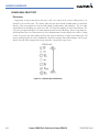
3.3 Crew Alerting System (CAS) ..............................3-13
CAS Messages and Prioritization ...............................3-14
CAS Display Inhibits .................................................3-16
SECTION 4 AUDIO PANEL AND CNS
4.1 Overview ...............................................................4-1
Audio Panel Volume Control .......................................4-1
PFD Controls and Frequency Display ............................4-2
Audio Panel Controls .................................................4-4
4.2 COM Operation .....................................................4-6
COM Transceiver Selection and Activation ....................4-6
COM Transceiver Manual Tuning .................................4-7
Quick-Tuning and Activating 121.500 MHz ...................4-8
Auto-Tuning the COM Frequency .................................4-9
Frequency Spacing ...................................................4-14
Automatic Squelch ...................................................4-15
Volume ...................................................................4-15
4.3 NAV Operation ....................................................4-16
NAV Radio Selection and Activation ..........................4-16
NAV Receiver Manual Tuning ....................................4-17
Auto-Tuning a NAV Frequency from the MFD .............4-19
Marker Beacon Receiver ...........................................4-24
ADF/DME Tuning .....................................................4-25

Garmin G1000 Pilot’s Guide for the Socata TBM 850
190-00709-00 Rev. Avi
TABLE OF CONTENTS
4.4 GTX 33/33D Mode S Transponders ...................4-29
Transponder Controls ...............................................4-29
Transponder Mode Selection .....................................4-30
Entering a Transponder Code ....................................4-33
IDENT Function .......................................................4-34
Flight ID Reporting ..................................................4-35
4.5 Additional Audio Panel Functions ....................4-36
Power-Up ................................................................4-36
Mono/Stereo Headsets .............................................4-36
Speaker ..................................................................4-36
Intercom .................................................................4-37
Passenger Address (PA) System .................................4-38
Simultaneous COM Operation ...................................4-38
Clearance Recorder and Player ..................................4-39
Entertainment Inputs ...............................................4-40
4.6 Audio Panels Preflight Procedure .....................4-41
4.7 Abnormal Operation ..........................................4-43
Stuck Microphone ....................................................4-43
COM Tuning Failure ..................................................4-43
PFD Failure, Dual System ..........................................4-44
Audio Panel Fail-Safe Operation ................................4-45
Reversionary Mode ..................................................4-45
SECTION 5 FLIGHT MANAGEMENT
5.1 Introduction ..........................................................5-1
Navigation Status Box ................................................5-3
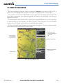
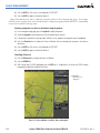
5.2 Using Map Displays ..............................................5-4
Map Orientation ........................................................5-4
Map Range ...............................................................5-6
Map Panning .............................................................5-9
Measuring Bearing and Distance ...............................5-14
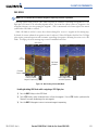
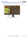
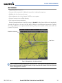
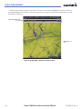
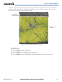
Topography .............................................................5-15
Map Symbols ..........................................................5-18
Airways ..................................................................5-24
Track Vector ............................................................5-26
Wind Vector ............................................................5-27
Nav Range Ring ......................................................5-28
Fuel Range Ring ......................................................5-29
5.3 Waypoints ............................................................5-30
Airports ..................................................................5-31
Intersections ...........................................................5-37
NDBs ......................................................................5-39
VORs ......................................................................5-41
User Waypoints .......................................................5-43
5.4 Airspaces .............................................................
5-48
5.5 Direct-to-Navigation .........................................5-53
5.6 Flight Planning ....................................................5-59
Flight Plan Creation .................................................5-60
Adding Waypoints To An Existing Flight Plan ..............5-63
Adding Airways to a Flight Plan ................................5-65
Adding Procedures To A Stored Flight Plan .................5-68
Flight Plan Storage ..................................................5-74
Flight Plan Editing ...................................................5-77
Along Track Offsets ..................................................5-80
Parallel Track ...........................................................5-82
Activating a Flight Plan Leg ......................................5-85
Inverting a Flight Plan ..............................................5-86
Flight Plan Views .....................................................5-87
Closest Point of FPL .................................................5-89
5.7 Vertical Navigation ............................................
5-90
Altitude Constraints .................................................5-92
5.8 Procedures ..........................................................5-96
Departures ..............................................................5-96
Arrivals ..................................................................5-99
Approaches ..........................................................5-101
5.9 Trip Planning .....................................................
5-107
Trip Planning .........................................................5-107
Weight Planning ....................................................5-111
Weight Caution And Warning Conditions .................5-113
5.10 RAIM Prediction ...............................................5-114
5.11 Navigating a Flight Plan ..................................5-118
5.12 Abnormal Operation ........................................5-146
SECTION 6 HAZARD AVOIDANCE
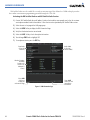
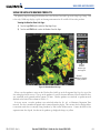
6.1 XM Satellite Weather ...........................................6-1
Using XM SATELLITE Weather Products ........................6-3
Weather Softkeys on the Weather Data Link Page .........6-6
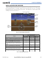
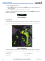
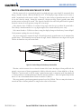
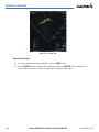
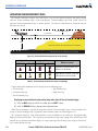
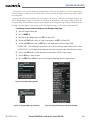
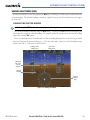
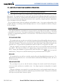
6.2 Airborne Color Weather Radar .........................6-29
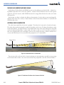
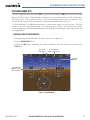
System Description ..................................................6-29
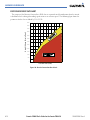
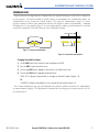
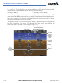
Principles of Pulsed Airborne Weather Radar ..............6-29
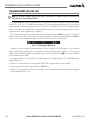
Safe Operating Distance ...........................................6-34
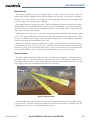
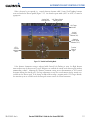
Basic Antenna Tilt Setup ...........................................6-34
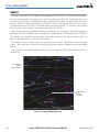
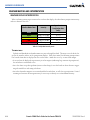
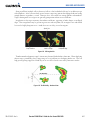
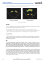
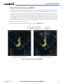
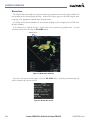
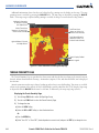
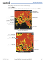
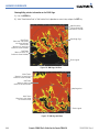
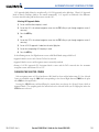
Weather Mapping and Interpretation ........................6-36
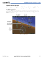
Ground Mapping and Interpretation ..........................6-49

190-00709-00 Rev. A
Garmin G1000 Pilot’s Guide for the Socata TBM 850
vii
TABLE OF CONTENTS
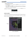
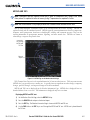
6.3 WX-500 Stormscope (Optional) ...........................6-50
Setting Up Stormscope on the Navigation Map ..........6-50
Selecting the Stormscope Page .................................6-54
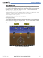
6.4 Terrain Proximity ................................................6-57
Displaying Terrain Proximity Data ..............................6-58
Terrain Proximity Page ..............................................6-60
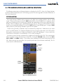
6.5 Terrain Awareness & Warning System (TAWS) 6-62
Displaying TAWS Data ..............................................6-63
TAWS Page .............................................................6-65
TAWS Alerts ............................................................6-67
System Status ..........................................................6-74
6.6 Traffic Advisory System (TAS) ...........................6-76
TAS Symbology ........................................................6-76
Operation ...............................................................6-77
Altitude Display .......................................................6-79
Traffic Map Page Display Range ................................6-80
TAS Alerts ...............................................................6-82
System Status ..........................................................6-82
SECTION 7 AUTOMATIC FLIGHT CONTROL SYSTEM
7.2 Flight Director Operation ....................................7-4
Activating the Flight Director ......................................7-4
AFCS Status Box ........................................................7-5
Flight Director Modes .................................................7-6
Switching Flight Directors ...........................................7-6
Command Bars ..........................................................7-7
7.3 Vertical Modes ......................................................7-8
Pitch Hold Mode (PIT) ................................................7-9
Selected Altitude Capture Mode (ALTS) ......................7-10
Altitude Hold Mode (ALT) .........................................7-11
Vertical Speed Mode (VS) .........................................7-12
Flight Level Change Mode (FLC) ................................7-13
Vertical Navigation Modes (VPTH, ALTV) ....................7-15
Glidepath Mode (GP) ...............................................7-20
Glideslope Mode (GS) ..............................................7-21
Takeoff (TO) and Go Around (GA) Modes ...................7-22
7.4 Lateral Modes .....................................................7-23
Roll Hold Mode (ROL) ..............................................7-24
Low Bank Mode ......................................................7-24
Heading Select Mode (HDG) .....................................7-25
Navigation Mode (GPS, VOR, LOC) ............................7-26
Approach Mode (GPS, VAPP, LOC) .............................7-28
Backcourse Mode (BC) .............................................7-30
7.5 Autopilot and Yaw Damper Operation ............7-31
Flight Control ..........................................................7-31
Engagement ............................................................7-32
Control Wheel Steering ............................................7-32
Disengagement .......................................................7-33
7.6 Example Flight Plan ...........................................7-34
Departure ...............................................................7-35
Intercepting a VOR Radial .........................................7-37
Flying a Flight Plan/GPS Course ................................7-38
Descent ..................................................................7-39
Approach ................................................................7-43
Go Around/Missed Approach ....................................7-45
7.6 AFCS Annunciations and Alerts ........................7-47
AFCS Status Alerts ...................................................7-47
Overspeed Protection ...............................................7-48
SECTION 8 ADDITIONAL FEATURES
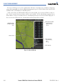
8.1 SafeTaxi .................................................................8-1
SafeTaxi Cycle Number and Revision ...........................8-4
8.2 ChartView ..............................................................8-7
ChartView Softkeys ....................................................8-7
Terminal Procedures Charts ........................................8-8
Chart Options ..........................................................8-18
Day/Night View .......................................................8-24
ChartView Cycle Number and Expiration Date ............8-26
8.3 FliteCharts ...........................................................8-30
FliteCharts Softkeys .................................................8-30
Terminal Procedures Charts ......................................8-31
Chart Options ..........................................................8-39
Day/Night View .......................................................8-43
FliteCharts Cycle Number and Expiration Date ............8-45
8.4 XM Radio Entertainment (Optional) ................8-49
Activating XM Satellite Radio Services .......................8-49
Using XM Radio ......................................................8-51
8.5 Scheduler .............................................................8-55
8.6 Electronic Checklists (Optional) .......................8-57
8.7 Abnormal Operation ..........................................8-60
APPENDICES
Annunciations and Alerts ..............................................A-1
CAS Messages ...........................................................A-1
Comparator Annunciations .........................................A-3
Reversionary Sensor Annunciations .............................A-4

Garmin G1000 Pilot’s Guide for the Socata TBM 850
190-00709-00 Rev. Aviii
TABLE OF CONTENTS
G1000 System Annunciations .....................................A-4
G1000 System Message Advisories ..............................A-7
AFCS Alerts .............................................................A-19
TAWS ALERTS ..........................................................A-20
Other G1000 Aural Alerts .........................................A-21
SD Card Use ....................................................................
B-1
Jeppesen Databases ...................................................B-1
Garmin Databases .....................................................B-2
Glossary ...........................................................................C-1
Frequently Asked Questions .........................................D-1
Map Symbols ..................................................................E-1
INDEX
Index ................................................................................I-1

190-00709-00 Rev. A
Garmin G1000 Pilot’s Guide for the Socata TBM 850
1-1
SYSTEM OVERVIEW
SECTION 1 SYSTEM OVERVIEW
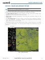
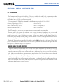
1.1 SYSTEM DESCRIPTION
This section is designed to provide an overview of the G1000 Integrated Flight Deck. The G1000 system is an
integrated flight control system that presents flight instrumentation, position, navigation, communication, and
identification information to the pilot through large-format displays. The system consists of the following Line
Replaceable Units (LRUs):
•
GDU 1040A
Primary Flight Display (PFD)
•
GDU 1500
Multi Function Display (MFD)
•
GIA 63W
Integrated Avionics Unit
•
GDC 74B
Air Data Computer (ADC)
•
GEA 71
Engine/Airframe Unit
•
GRS 77
Attitude and Heading Reference System
(AHRS)
•
GMU 44
Magnetometer
•
GMA 1347D Cabin
Dual Audio System with
Integrated Marker Beacon Receiver
•
GTX 33/33D
Mode S Transponder
•
GDL 69A
Data Link
•
GWX 68
Weather Radar
•
GCU 475
MFD Control Unit
•
GMC 710
AFCS Control Unit
•
GA 36
and
GA 37
GPS/WAAS Antennas
•
GSA 81
AFCS Servos
•
GSM 85
Servo Gearboxes
•
GTA 82
Trim Adapter
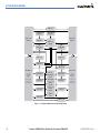
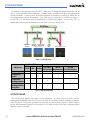
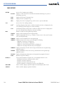
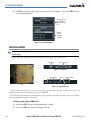
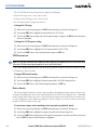
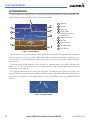
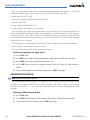
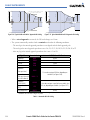
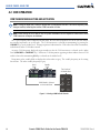
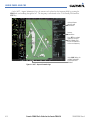
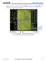
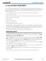
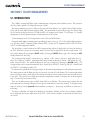
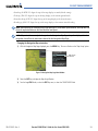
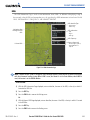
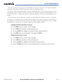
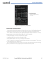
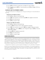
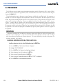
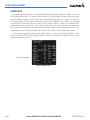
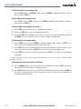
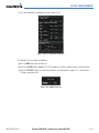
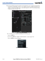
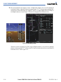
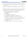
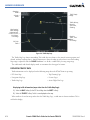
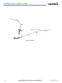
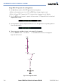
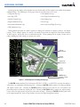
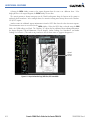
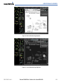
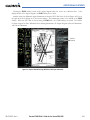
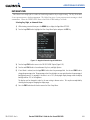
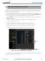
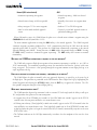
A top-level G1000 system block diagram is shown in Figure 1-1 (it does not include the GA 36, GA 37, or GSM
85).
NOTE: Refer to the AFCS section for details on the GFC 700 AFCS.
In the aircraft, the GFC 700 Automated Flight Control System (AFCS) provides the Flight Director (FD),
Autopilot (AP), and Yaw Damper (YD) functions of the G1000 system.

Garmin G1000 Pilot’s Guide for the Socata TBM 850
190-00709-00 Rev. A1-2
SYSTEM OVERVIEW
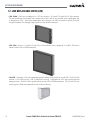
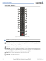
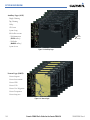
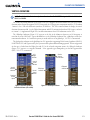
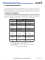
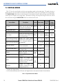
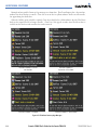
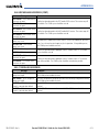
1.2 LINE REPLACEABLE UNITS (LRU)
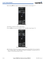
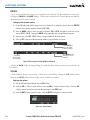
•
GDU 1040A
– Each unit is configured as a PFD that features a 10.4-inch LCD with 1024 x 768 resolution.
The unit installed on the left/pilot side is designated as PFD1, and the one installed on the right/copilot side
is designated as PFD2. These units communicate with each other, the MFD, and with the on-side GIA 63W
Integrated Avionics Unit through a High-Speed Data Bus (HSDB) connection.
•
GDU 1500
– Features a 15-inch LCD with 1024 x 768 resolution and is configured as an MFD. This unit is
linked to both PFDs via HSDB connection.
•
GIA 63W
– Functions as the main communication hub, linking all LRUs with the on-side PFD. Each GIA 63W
contains a GPS WAAS receiver, VHF COM/NAV/GS receivers, a flight director (FD) and system integration
microprocessors. Each GIA 63W is paired with the on-side PFD via HSDB connection. The GIA 63Ws are not
paired together and do not communicate with each other directly.

190-00709-00 Rev. A
Garmin G1000 Pilot’s Guide for the Socata TBM 850
1-3
SYSTEM OVERVIEW
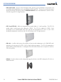
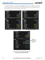
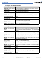
•
GDC 74B
– Processes data from the pitot/static system as well as the OAT probe. This unit provides pressure
altitude, airspeed, vertical speed and OAT information to the G1000 system, and it communicates with the on-
side GIA 63W, on-side GDU 1040A and on-side GRS 77, using an ARINC 429 digital interface (it also interfaces
directly with the OAT). The GDC 74B is designed to operate in Reduced Vertical Separation Minimum (RVSM)
airspace.
•
GEA 71
– Receives and processes signals from the engine and airframe sensors. This unit communicates with
both GIA 63Ws using an RS-485 digital interface.
•
GRS 77
– Provides aircraft attitude and heading information via ARINC 429 to both the on-side GDU 1040A
and the on-side GIA 63W. The GRS 77 contains advanced sensors (including accelerometers and rate sensors)
and interfaces with the on-side GMU 44 to obtain magnetic field information, with the GDC 74B to obtain air
data, and with both GIA 63Ws to obtain GPS information. AHRS modes of operation are discussed later in this
document.
•
GMU 44
– Measures local magnetic field. Data is sent to the GRS 77 for processing to determine aircraft
magnetic heading. This unit receives power directly from the GRS 77 and communicates with the GRS 77,
using an RS-485 digital interface.

Garmin G1000 Pilot’s Guide for the Socata TBM 850
190-00709-00 Rev. A1-4
SYSTEM OVERVIEW
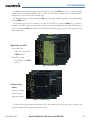
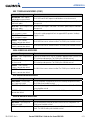
•
GMA 1347D Cabin
– Integrates NAV/COM digital audio, intercom system and marker beacon controls, and
is installed in dual configuration on the outboard side of PFD1 and PFD2. This unit also enables the manual
control of the display reversionary mode (red
DISPLAY BACKUP
button) and communicates with the on-side
GIA 63W, using an RS-232 digital interface.
•
GTX 33 and GTX 33D
– Solid-state transponders that provide Modes A, C and S capability. The GTX 33D
includes Mode S with diversity and is indicated as ‘XPDR1’. The GTX 33 is indicated as ‘XPDR2’. Both
transponders can be controlled from either PFD, and only one transponder can be active at a time. Each
transponder communicates with the on-side GIA 63W through an RS-232 digital interface.
•
GDL 69A
– A satellite radio receiver that provides real-time weather information to the G1000 MFD (and,
indirectly, to the inset map of the PFD) as well as digital audio entertainment. The GDL 69A communicates
with the MFD via HSDB connection. A subscription to the XM Satellite Radio service is required to enable the
GDL 69A capability.
•
GWX 68
– Provides airborne weather and ground mapped radar data to the MFD, through the GDL 69A, via
HSDB connection.

190-00709-00 Rev. A
Garmin G1000 Pilot’s Guide for the Socata TBM 850
1-5
SYSTEM OVERVIEW
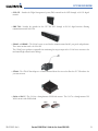
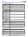
•
GCU 475
– Provides the Flight Management System (FMS) controls for the MFD through an RS-232 digital
interface.
•
GMC 710
– Provides the controls for the GFC 700 AFCS through an RS-232 digital interface allowing
communication with both PFDs.
•
GSA 81
, and
GSM 85
– The GSA 81 servos are used for the automatic control of roll, yaw, pitch, and pitch trim.
These units interface with each GIA 63W.
The GSM 85 servo gearbox is responsible for transferring the output torque of the GSA 81 servo actuator to the
mechanical flight-control surface linkage.
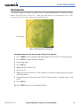
•
GTA 82
– The GTA 82 Trim Adapter is a remote mounted device that is used to allow the GFC 700 to drive the
yaw trim actuator.
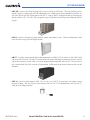
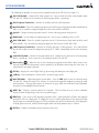
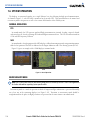
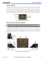
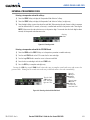
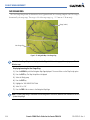
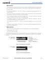
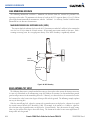
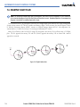
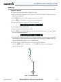
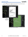
•
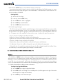
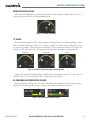
GA 36
and
GA 37
– The GA 36 is a through-mount GPS/WAAS antenna. The GA 37 is a through-mount GPS/
WAAS antenna with XM/Datalink.
GA 36 GA 37

Garmin G1000 Pilot’s Guide for the Socata TBM 850
190-00709-00 Rev. A1-6
SYSTEM OVERVIEW
GDU 1040A
(PFD #1)
GDU 1040A
(PFD #2)
GDU 1500
(MFD)
GIA 63W #2
GSA 81
(Yaw)
GSA 81
(Roll)
GSA 81
(Pitch)
GSA 81
(Pitch Trim)
GRS 77 #1
GIA 63W #1
GMC 710
GMU 44 #1
GEA 71 #2
GEA 71 #1
GDC 74B #1
OAT Probe
GMA
1347D Cabin
#2
GMA
1347D Cabin
#1
GTX 33D GTX 33
GCU 475GWX 68
GDL 69A
GRS 77 #2
GMU 44 #2
GDC 74B #2
OAT Probe
VHF COM
VHF NAV/LOC
GPS/WAAS
G/S
AFCS Mode Logic
Flight Director
Servo Management
VHF COM
VHF NAV/LOC
GPS/WAAS
G/S
AFCS Mode Logic
Flight Director
Servo Management
GTA 82
(Trim Adapter)
Figure 1-1 Example G1000 System (LRU Configuration)

190-00709-00 Rev. A
Garmin G1000 Pilot’s Guide for the Socata TBM 850
1-7
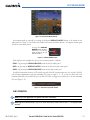
SYSTEM OVERVIEW
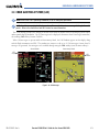
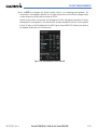
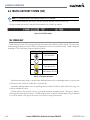
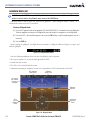
1.3 G1000 CONTROLS
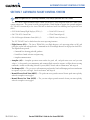
NOTE: The Audio Panel (GMA 1347D Cabin) and AFCS controls (GMC 710) are described in the CNS & Audio
Panel and AFCS sections respectively.
The G1000 system controls are located on the PFD and MFD bezels, MFD Control Unit, AFCS Control Unit and
audio panel. The controls for the PFD and MFD are discussed within the following pages of this section.
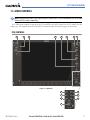
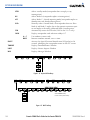
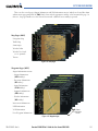
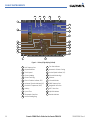
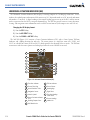
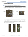
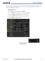
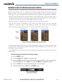
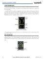
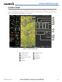
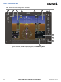
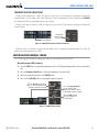
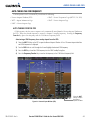
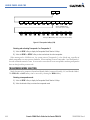
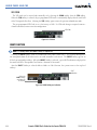
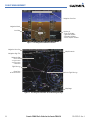
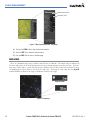
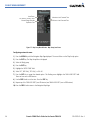
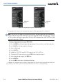
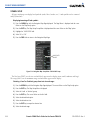
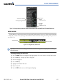
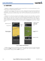
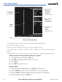
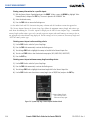
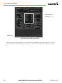
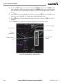
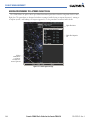
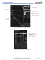
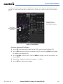
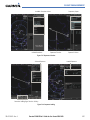
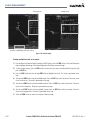
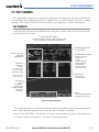
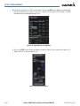
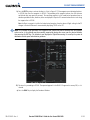
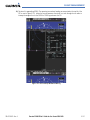
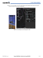
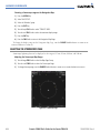
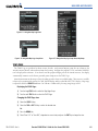
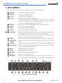
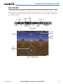
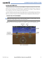
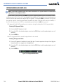
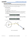
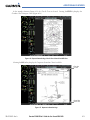
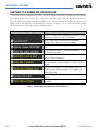
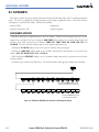
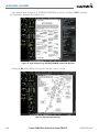
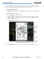
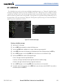
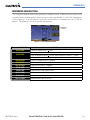
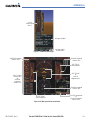
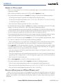
PFD CONTROLS
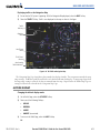
Figure 1-2 PFD Controls
21 5
4
6
8
7
3
11
12
10
9
15
14
13

Garmin G1000 Pilot’s Guide for the Socata TBM 850
190-00709-00 Rev. A1-8
SYSTEM OVERVIEW
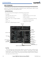
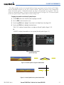
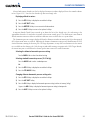
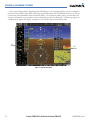
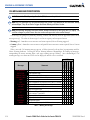
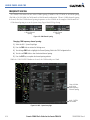
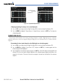
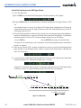
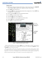
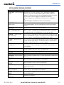
The following list provides an overview of the controls located on the PFD bezel (see Figure 1-2).
1
NAV VOL/ID Knob
– Controls NAV audio volume level. Press to switch the Morse code identifier audio
ON and OFF. Volume level is shown in the NAV frequency field as a percentage.
2
NAV Frequency Transfer Key
– Switches the standby and active NAV frequencies.
3
Dual
NAV Knob
– Tunes the standby frequencies for the NAV receiver (large knob for MHz; small knob for
kHz). Press to switch the tuning box (light blue box) between NAV1 and NAV2.
4
Joystick
– Changes the map range when rotated. Activates the map pointer when pressed.
5
BARO Knob
– Sets the altimeter barometric pressure. Press to enter standard pressure (29.92).
6
Dual COM Knob
– Tunes the standby frequencies for the COM transceiver (large knob for MHz; small
knob for kHz). Press to switch the tuning box (light blue box) between COM1 and COM2.
7
COM Frequency Transfer Key
– Switches the standby and active COM frequencies. Press and hold this
key for two seconds to tune the emergency frequency (121.5 MHz) automatically into the active frequency
field.
8
COM
VOL/SQ Knob
– Controls COM audio volume level. Volume level is shown in the COM frequency
field as a percentage. Press to turn the COM automatic squelch ON and OFF.
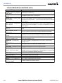
9
Direct-to Key ( )
– Allows the user to enter a destination waypoint and establish a direct course to the
selected destination (the destination is either specified by the identifier, chosen from the active route, or
taken from the map pointer position).
10
FPL Key
– Displays the active Flight Plan Page for creating and editing the active flight plan.
11
CLR
Key
– Erases information, cancels entries, or removes page menus.
12
Dual FMS Knob
– Flight Management System Knob. Press the
FMS
Knob to turn the selection cursor
ON and OFF. When the cursor is ON, data may be entered in the applicable window by turning the small
and large
knobs. The large
knob moves the cursor on the page, while the small
knob selects individual
characters for the highlighted cursor location.
13
MENU Key
– Displays a context-sensitive list of options. This list allows the user to access additional
features or make setting changes that relate to particular pages.
14
PROC Key
– Gives access to IFR departure procedures (DPs), arrival procedures (STARs) and approach
procedures (IAPs) for a flight plan. If a flight plan is used, available procedures for the departure and/or
arrival airport are automatically suggested. These procedures can then be loaded into the active flight plan.
If a flight plan is not used, both the desired airport and the desired procedure may be selected.
15
ENT Key
– Validates or confirms a menu selection or data entry.

190-00709-00 Rev. A
Garmin G1000 Pilot’s Guide for the Socata TBM 850
1-9
SYSTEM OVERVIEW
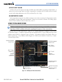
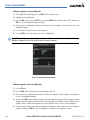
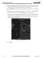
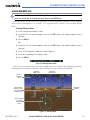
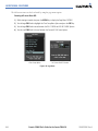
CONTROLS ASSOCIATED WITH THE MFD
The controls for the MFD (GDU 1500) are located on both the MFD bezel and the MFD Control Unit (GCU
475). The bottom portion of the MFD bezel features 12 softkeys that are designed to perform various functions
depending upon the control display mode and the specific page being displayed. These softkeys are discussed
throughout the this documentation.
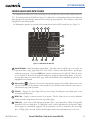
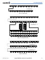
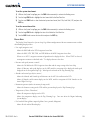
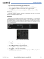
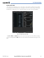
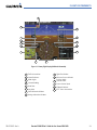
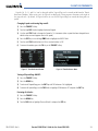
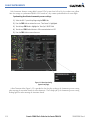
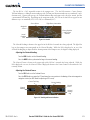
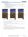
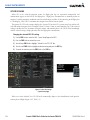
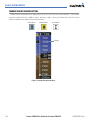
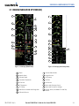
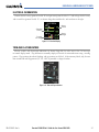
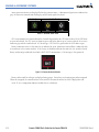
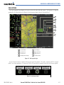
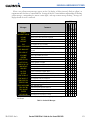
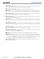
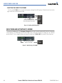
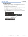
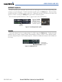
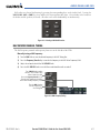
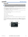
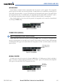
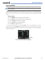
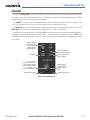
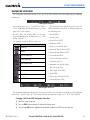
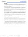
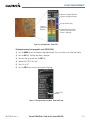
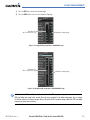
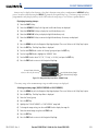
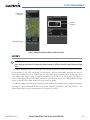
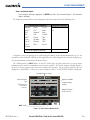
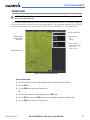
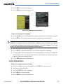
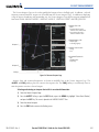
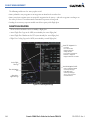
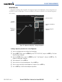
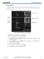
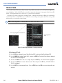
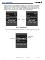
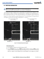
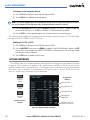
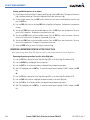
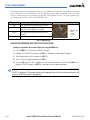
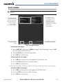
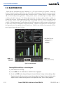
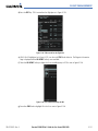
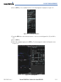
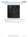
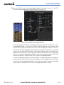
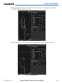
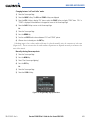
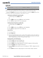
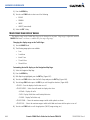
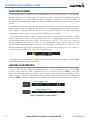
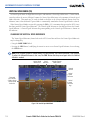
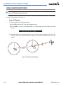
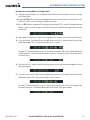
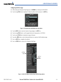
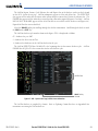
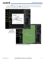
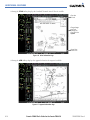
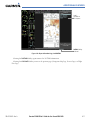
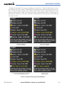
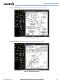
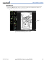
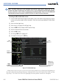
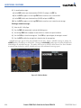
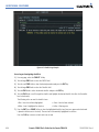
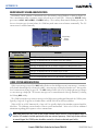
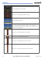
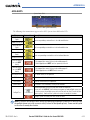
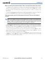
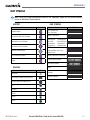
The following list provides an overview of the controls located on the MFD Control Unit (see Figure 1-3):
3 4 52
6
7
8
9
13 12 11 10
Figure 1-3 MFD Control Unit (GCU 475)
1
14
1
Dual FMS Knob
– Flight Management System Knob. This knob selects the MFD page to be viewed; the
large
knob selects a page group (MAP, WPT, AUX, NRST), while the small
knob selects a specific page
within the page group. Pressing the
FMS
Knob turns the selection cursor ON and OFF. When the cursor
is ON, data may be entered in the applicable window by turning the small and large
knobs. In this case,
the large
knob moves the cursor on the page, while the small
knob selects individual characters for the
highlighted cursor location.
2
Direct-to Key ( )
– Allows the user to enter a destination waypoint and establish a direct course to the
selected destination (the destination is either specified by the identifier, chosen from the active route, or
taken from the map pointer position).
3
FPL Key
– Displays the active Flight Plan Page for creating and editing the active flight plan, or for
accessing stored flight plans.
4
MENU Key
– Displays a context-sensitive list of options. This list allows the user to access additional
features or make setting changes that relate to particular pages.
5
PROC Key
– Gives access to IFR departure procedures (DPs), arrival procedures (STARs) and approach
procedures (IAPs) for a flight plan. If a flight plan is used, available procedures for the departure and/or
arrival airport are automatically suggested. Theses procedures can then be loaded into the active flight
plan. If a flight plan is not used, both the desired airport and the desired procedure may be selected.

Garmin G1000 Pilot’s Guide for the Socata TBM 850
190-00709-00 Rev. A1-10
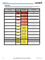
SYSTEM OVERVIEW
6
Joystick
– Changes the map range when rotated. Activates the map pointer when pressed.
7
Alphanumeric Keys
– Allow the user to enter data quickly, without having to select individual characters
with the
FMS
Knob.
8
Plus (+) Minus (-) Key
– Switches between a (+) or (-) character.
9
Decimal Key
– Enters a decimal point.
10
SEL Key
– The center of this key activates the selected softkey, while the right and left arrows move the
softkey selection box to the right and left, respectively.
11
ENT Key
– Validates or confirms a menu selection or data entry.
12
CLR
Key
– Erases information, cancels entries, or removes page menus. Pressing and holding this key
displays the Navigation Map Page automatically.
13
SPC Key
– Adds a space character.
14
BKSP Key
– Moves the cursor back one character space.
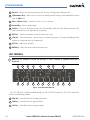
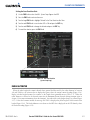
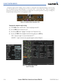
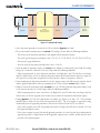
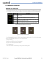
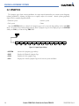
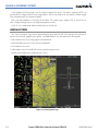
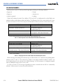
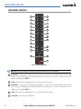
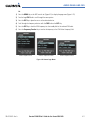
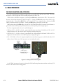
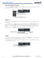
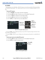
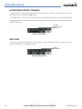
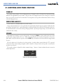
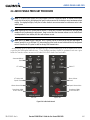
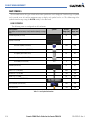
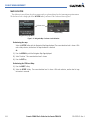
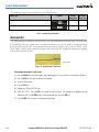
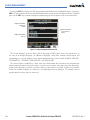
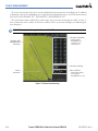
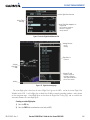
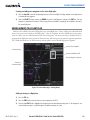
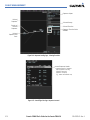
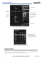
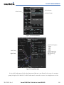
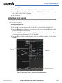
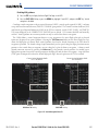
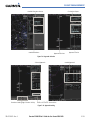
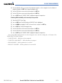
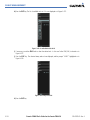
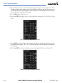
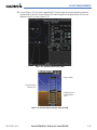
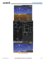
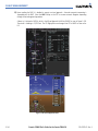
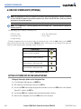
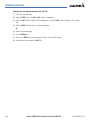
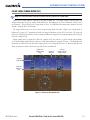
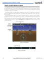
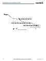
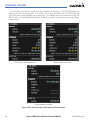
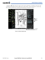
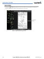
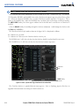
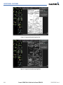
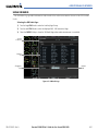
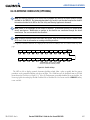
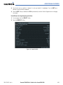
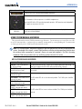
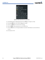
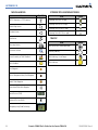
AFCS CONTROLS
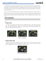
NOTE: With the exception of the
FD
and
SPD
Keys, if a key is selected, its respective annunciator is
illuminated.
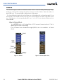
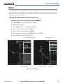
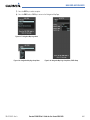
1 2 3 4 5 6 7 8
10 917 16 15 14 13 12 111819
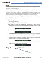
Figure 1-4 AFCS Control Unit (GMC 710)
The GFC 700 AFCS is mainly controlled through the GMC 710 AFCS Control Unit. The AFCS Control Unit
consists of the following controls:
1
HDG Key
– Selects/deselects the Heading Select mode.
2
APR Key
– Selects/deselects the Approach mode.
3
NAV Key
– Selects/deselects the Navigation mode.
Page is loading ...
Page is loading ...
Page is loading ...
Page is loading ...
Page is loading ...
Page is loading ...
Page is loading ...
Page is loading ...
Page is loading ...
Page is loading ...
Page is loading ...
Page is loading ...
Page is loading ...
Page is loading ...
Page is loading ...
Page is loading ...
Page is loading ...
Page is loading ...
Page is loading ...
Page is loading ...
Page is loading ...
Page is loading ...
Page is loading ...
Page is loading ...
Page is loading ...
Page is loading ...
Page is loading ...
Page is loading ...
Page is loading ...
Page is loading ...
Page is loading ...
Page is loading ...
Page is loading ...
Page is loading ...
Page is loading ...
Page is loading ...
Page is loading ...
Page is loading ...
Page is loading ...
Page is loading ...
Page is loading ...
Page is loading ...
Page is loading ...
Page is loading ...
Page is loading ...
Page is loading ...
Page is loading ...
Page is loading ...
Page is loading ...
Page is loading ...
Page is loading ...
Page is loading ...
Page is loading ...
Page is loading ...
Page is loading ...
Page is loading ...
Page is loading ...
Page is loading ...
Page is loading ...
Page is loading ...
Page is loading ...
Page is loading ...
Page is loading ...
Page is loading ...
Page is loading ...
Page is loading ...
Page is loading ...
Page is loading ...
Page is loading ...
Page is loading ...
Page is loading ...
Page is loading ...
Page is loading ...
Page is loading ...
Page is loading ...
Page is loading ...
Page is loading ...
Page is loading ...
Page is loading ...
Page is loading ...
Page is loading ...
Page is loading ...
Page is loading ...
Page is loading ...
Page is loading ...
Page is loading ...
Page is loading ...
Page is loading ...
Page is loading ...
Page is loading ...
Page is loading ...
Page is loading ...
Page is loading ...
Page is loading ...
Page is loading ...
Page is loading ...
Page is loading ...
Page is loading ...
Page is loading ...
Page is loading ...
Page is loading ...
Page is loading ...
Page is loading ...
Page is loading ...
Page is loading ...
Page is loading ...
Page is loading ...
Page is loading ...
Page is loading ...
Page is loading ...
Page is loading ...
Page is loading ...
Page is loading ...
Page is loading ...
Page is loading ...
Page is loading ...
Page is loading ...
Page is loading ...
Page is loading ...
Page is loading ...
Page is loading ...
Page is loading ...
Page is loading ...
Page is loading ...
Page is loading ...
Page is loading ...
Page is loading ...
Page is loading ...
Page is loading ...
Page is loading ...
Page is loading ...
Page is loading ...
Page is loading ...
Page is loading ...
Page is loading ...
Page is loading ...
Page is loading ...
Page is loading ...
Page is loading ...
Page is loading ...
Page is loading ...
Page is loading ...
Page is loading ...
Page is loading ...
Page is loading ...
Page is loading ...
Page is loading ...
Page is loading ...
Page is loading ...
Page is loading ...
Page is loading ...
Page is loading ...
Page is loading ...
Page is loading ...
Page is loading ...
Page is loading ...
Page is loading ...
Page is loading ...
Page is loading ...
Page is loading ...
Page is loading ...
Page is loading ...
Page is loading ...
Page is loading ...
Page is loading ...
Page is loading ...
Page is loading ...
Page is loading ...
Page is loading ...
Page is loading ...
Page is loading ...
Page is loading ...
Page is loading ...
Page is loading ...
Page is loading ...
Page is loading ...
Page is loading ...
Page is loading ...
Page is loading ...
Page is loading ...
Page is loading ...
Page is loading ...
Page is loading ...
Page is loading ...
Page is loading ...
Page is loading ...
Page is loading ...
Page is loading ...
Page is loading ...
Page is loading ...
Page is loading ...
Page is loading ...
Page is loading ...
Page is loading ...
Page is loading ...
Page is loading ...
Page is loading ...
Page is loading ...
Page is loading ...
Page is loading ...
Page is loading ...
Page is loading ...
Page is loading ...
Page is loading ...
Page is loading ...
Page is loading ...
Page is loading ...
Page is loading ...
Page is loading ...
Page is loading ...
Page is loading ...
Page is loading ...
Page is loading ...
Page is loading ...
Page is loading ...
Page is loading ...
Page is loading ...
Page is loading ...
Page is loading ...
Page is loading ...
Page is loading ...
Page is loading ...
Page is loading ...
Page is loading ...
Page is loading ...
Page is loading ...
Page is loading ...
Page is loading ...
Page is loading ...
Page is loading ...
Page is loading ...
Page is loading ...
Page is loading ...
Page is loading ...
Page is loading ...
Page is loading ...
Page is loading ...
Page is loading ...
Page is loading ...
Page is loading ...
Page is loading ...
Page is loading ...
Page is loading ...
Page is loading ...
Page is loading ...
Page is loading ...
Page is loading ...
Page is loading ...
Page is loading ...
Page is loading ...
Page is loading ...
Page is loading ...
Page is loading ...
Page is loading ...
Page is loading ...
Page is loading ...
Page is loading ...
Page is loading ...
Page is loading ...
Page is loading ...
Page is loading ...
Page is loading ...
Page is loading ...
Page is loading ...
Page is loading ...
Page is loading ...
Page is loading ...
Page is loading ...
Page is loading ...
Page is loading ...
Page is loading ...
Page is loading ...
Page is loading ...
Page is loading ...
Page is loading ...
Page is loading ...
Page is loading ...
Page is loading ...
Page is loading ...
Page is loading ...
Page is loading ...
Page is loading ...
Page is loading ...
Page is loading ...
Page is loading ...
Page is loading ...
Page is loading ...
Page is loading ...
Page is loading ...
Page is loading ...
Page is loading ...
Page is loading ...
Page is loading ...
Page is loading ...
Page is loading ...
Page is loading ...
Page is loading ...
Page is loading ...
Page is loading ...
Page is loading ...
Page is loading ...
Page is loading ...
Page is loading ...
Page is loading ...
Page is loading ...
Page is loading ...
Page is loading ...
Page is loading ...
Page is loading ...
Page is loading ...
Page is loading ...
Page is loading ...
Page is loading ...
Page is loading ...
Page is loading ...
Page is loading ...
Page is loading ...
Page is loading ...
Page is loading ...
Page is loading ...
Page is loading ...
Page is loading ...
Page is loading ...
Page is loading ...
Page is loading ...
Page is loading ...
Page is loading ...
Page is loading ...
Page is loading ...
Page is loading ...
Page is loading ...
Page is loading ...
Page is loading ...
Page is loading ...
Page is loading ...
Page is loading ...
Page is loading ...
Page is loading ...
Page is loading ...
Page is loading ...
Page is loading ...
Page is loading ...
Page is loading ...
Page is loading ...
Page is loading ...
Page is loading ...
Page is loading ...
Page is loading ...
Page is loading ...
Page is loading ...
Page is loading ...
Page is loading ...
Page is loading ...
Page is loading ...
Page is loading ...
Page is loading ...
Page is loading ...
Page is loading ...
Page is loading ...
Page is loading ...
Page is loading ...
Page is loading ...
Page is loading ...
Page is loading ...
Page is loading ...
Page is loading ...
Page is loading ...
Page is loading ...
Page is loading ...
Page is loading ...
Page is loading ...
Page is loading ...
Page is loading ...
Page is loading ...
Page is loading ...
Page is loading ...
Page is loading ...
Page is loading ...
Page is loading ...
Page is loading ...
Page is loading ...
Page is loading ...
Page is loading ...
Page is loading ...
Page is loading ...
Page is loading ...
Page is loading ...
Page is loading ...
Page is loading ...
Page is loading ...
Page is loading ...
Page is loading ...
Page is loading ...
Page is loading ...
Page is loading ...
Page is loading ...
Page is loading ...
Page is loading ...
Page is loading ...
Page is loading ...
Page is loading ...
Page is loading ...
Page is loading ...
Page is loading ...
Page is loading ...
Page is loading ...
Page is loading ...
Page is loading ...
Page is loading ...
Page is loading ...
Page is loading ...
Page is loading ...
Page is loading ...
Page is loading ...
Page is loading ...
Page is loading ...
Page is loading ...
Page is loading ...
Page is loading ...
Page is loading ...
Page is loading ...
Page is loading ...
Page is loading ...
Page is loading ...
Page is loading ...
Page is loading ...
Page is loading ...
Page is loading ...
Page is loading ...
Page is loading ...
Page is loading ...
Page is loading ...
Page is loading ...
Page is loading ...
Page is loading ...
Page is loading ...
Page is loading ...
Page is loading ...
Page is loading ...
Page is loading ...
Page is loading ...
Page is loading ...
Page is loading ...
Page is loading ...
Page is loading ...
Page is loading ...
Page is loading ...
Page is loading ...
Page is loading ...
Page is loading ...
Page is loading ...
Page is loading ...
Page is loading ...
Page is loading ...
Page is loading ...
Page is loading ...
Page is loading ...
Page is loading ...
Page is loading ...
Page is loading ...
Page is loading ...
Page is loading ...
Page is loading ...
Page is loading ...
Page is loading ...
Page is loading ...
Page is loading ...
Page is loading ...
Page is loading ...
Page is loading ...
Page is loading ...
Page is loading ...
Page is loading ...
Page is loading ...
Page is loading ...
Page is loading ...
Page is loading ...
Page is loading ...
Page is loading ...
Page is loading ...
Page is loading ...
Page is loading ...
Page is loading ...
Page is loading ...
Page is loading ...
Page is loading ...
Page is loading ...
Page is loading ...
Page is loading ...
Page is loading ...
Page is loading ...
Page is loading ...
Page is loading ...
Page is loading ...
Page is loading ...
Page is loading ...
Page is loading ...
Page is loading ...
Page is loading ...
Page is loading ...
Page is loading ...
Page is loading ...
Page is loading ...
Page is loading ...
Page is loading ...
Page is loading ...
Page is loading ...
Page is loading ...
Page is loading ...
Page is loading ...
Page is loading ...
Page is loading ...
Page is loading ...
Page is loading ...
Page is loading ...
Page is loading ...
Page is loading ...
Page is loading ...
Page is loading ...
Page is loading ...
Page is loading ...
Page is loading ...
-
 1
1
-
 2
2
-
 3
3
-
 4
4
-
 5
5
-
 6
6
-
 7
7
-
 8
8
-
 9
9
-
 10
10
-
 11
11
-
 12
12
-
 13
13
-
 14
14
-
 15
15
-
 16
16
-
 17
17
-
 18
18
-
 19
19
-
 20
20
-
 21
21
-
 22
22
-
 23
23
-
 24
24
-
 25
25
-
 26
26
-
 27
27
-
 28
28
-
 29
29
-
 30
30
-
 31
31
-
 32
32
-
 33
33
-
 34
34
-
 35
35
-
 36
36
-
 37
37
-
 38
38
-
 39
39
-
 40
40
-
 41
41
-
 42
42
-
 43
43
-
 44
44
-
 45
45
-
 46
46
-
 47
47
-
 48
48
-
 49
49
-
 50
50
-
 51
51
-
 52
52
-
 53
53
-
 54
54
-
 55
55
-
 56
56
-
 57
57
-
 58
58
-
 59
59
-
 60
60
-
 61
61
-
 62
62
-
 63
63
-
 64
64
-
 65
65
-
 66
66
-
 67
67
-
 68
68
-
 69
69
-
 70
70
-
 71
71
-
 72
72
-
 73
73
-
 74
74
-
 75
75
-
 76
76
-
 77
77
-
 78
78
-
 79
79
-
 80
80
-
 81
81
-
 82
82
-
 83
83
-
 84
84
-
 85
85
-
 86
86
-
 87
87
-
 88
88
-
 89
89
-
 90
90
-
 91
91
-
 92
92
-
 93
93
-
 94
94
-
 95
95
-
 96
96
-
 97
97
-
 98
98
-
 99
99
-
 100
100
-
 101
101
-
 102
102
-
 103
103
-
 104
104
-
 105
105
-
 106
106
-
 107
107
-
 108
108
-
 109
109
-
 110
110
-
 111
111
-
 112
112
-
 113
113
-
 114
114
-
 115
115
-
 116
116
-
 117
117
-
 118
118
-
 119
119
-
 120
120
-
 121
121
-
 122
122
-
 123
123
-
 124
124
-
 125
125
-
 126
126
-
 127
127
-
 128
128
-
 129
129
-
 130
130
-
 131
131
-
 132
132
-
 133
133
-
 134
134
-
 135
135
-
 136
136
-
 137
137
-
 138
138
-
 139
139
-
 140
140
-
 141
141
-
 142
142
-
 143
143
-
 144
144
-
 145
145
-
 146
146
-
 147
147
-
 148
148
-
 149
149
-
 150
150
-
 151
151
-
 152
152
-
 153
153
-
 154
154
-
 155
155
-
 156
156
-
 157
157
-
 158
158
-
 159
159
-
 160
160
-
 161
161
-
 162
162
-
 163
163
-
 164
164
-
 165
165
-
 166
166
-
 167
167
-
 168
168
-
 169
169
-
 170
170
-
 171
171
-
 172
172
-
 173
173
-
 174
174
-
 175
175
-
 176
176
-
 177
177
-
 178
178
-
 179
179
-
 180
180
-
 181
181
-
 182
182
-
 183
183
-
 184
184
-
 185
185
-
 186
186
-
 187
187
-
 188
188
-
 189
189
-
 190
190
-
 191
191
-
 192
192
-
 193
193
-
 194
194
-
 195
195
-
 196
196
-
 197
197
-
 198
198
-
 199
199
-
 200
200
-
 201
201
-
 202
202
-
 203
203
-
 204
204
-
 205
205
-
 206
206
-
 207
207
-
 208
208
-
 209
209
-
 210
210
-
 211
211
-
 212
212
-
 213
213
-
 214
214
-
 215
215
-
 216
216
-
 217
217
-
 218
218
-
 219
219
-
 220
220
-
 221
221
-
 222
222
-
 223
223
-
 224
224
-
 225
225
-
 226
226
-
 227
227
-
 228
228
-
 229
229
-
 230
230
-
 231
231
-
 232
232
-
 233
233
-
 234
234
-
 235
235
-
 236
236
-
 237
237
-
 238
238
-
 239
239
-
 240
240
-
 241
241
-
 242
242
-
 243
243
-
 244
244
-
 245
245
-
 246
246
-
 247
247
-
 248
248
-
 249
249
-
 250
250
-
 251
251
-
 252
252
-
 253
253
-
 254
254
-
 255
255
-
 256
256
-
 257
257
-
 258
258
-
 259
259
-
 260
260
-
 261
261
-
 262
262
-
 263
263
-
 264
264
-
 265
265
-
 266
266
-
 267
267
-
 268
268
-
 269
269
-
 270
270
-
 271
271
-
 272
272
-
 273
273
-
 274
274
-
 275
275
-
 276
276
-
 277
277
-
 278
278
-
 279
279
-
 280
280
-
 281
281
-
 282
282
-
 283
283
-
 284
284
-
 285
285
-
 286
286
-
 287
287
-
 288
288
-
 289
289
-
 290
290
-
 291
291
-
 292
292
-
 293
293
-
 294
294
-
 295
295
-
 296
296
-
 297
297
-
 298
298
-
 299
299
-
 300
300
-
 301
301
-
 302
302
-
 303
303
-
 304
304
-
 305
305
-
 306
306
-
 307
307
-
 308
308
-
 309
309
-
 310
310
-
 311
311
-
 312
312
-
 313
313
-
 314
314
-
 315
315
-
 316
316
-
 317
317
-
 318
318
-
 319
319
-
 320
320
-
 321
321
-
 322
322
-
 323
323
-
 324
324
-
 325
325
-
 326
326
-
 327
327
-
 328
328
-
 329
329
-
 330
330
-
 331
331
-
 332
332
-
 333
333
-
 334
334
-
 335
335
-
 336
336
-
 337
337
-
 338
338
-
 339
339
-
 340
340
-
 341
341
-
 342
342
-
 343
343
-
 344
344
-
 345
345
-
 346
346
-
 347
347
-
 348
348
-
 349
349
-
 350
350
-
 351
351
-
 352
352
-
 353
353
-
 354
354
-
 355
355
-
 356
356
-
 357
357
-
 358
358
-
 359
359
-
 360
360
-
 361
361
-
 362
362
-
 363
363
-
 364
364
-
 365
365
-
 366
366
-
 367
367
-
 368
368
-
 369
369
-
 370
370
-
 371
371
-
 372
372
-
 373
373
-
 374
374
-
 375
375
-
 376
376
-
 377
377
-
 378
378
-
 379
379
-
 380
380
-
 381
381
-
 382
382
-
 383
383
-
 384
384
-
 385
385
-
 386
386
-
 387
387
-
 388
388
-
 389
389
-
 390
390
-
 391
391
-
 392
392
-
 393
393
-
 394
394
-
 395
395
-
 396
396
-
 397
397
-
 398
398
-
 399
399
-
 400
400
-
 401
401
-
 402
402
-
 403
403
-
 404
404
-
 405
405
-
 406
406
-
 407
407
-
 408
408
-
 409
409
-
 410
410
-
 411
411
-
 412
412
-
 413
413
-
 414
414
-
 415
415
-
 416
416
-
 417
417
-
 418
418
-
 419
419
-
 420
420
-
 421
421
-
 422
422
-
 423
423
-
 424
424
-
 425
425
-
 426
426
-
 427
427
-
 428
428
-
 429
429
-
 430
430
-
 431
431
-
 432
432
-
 433
433
-
 434
434
-
 435
435
-
 436
436
-
 437
437
-
 438
438
-
 439
439
-
 440
440
-
 441
441
-
 442
442
-
 443
443
-
 444
444
-
 445
445
-
 446
446
-
 447
447
-
 448
448
-
 449
449
-
 450
450
-
 451
451
-
 452
452
-
 453
453
-
 454
454
-
 455
455
-
 456
456
-
 457
457
-
 458
458
-
 459
459
-
 460
460
-
 461
461
-
 462
462
-
 463
463
-
 464
464
-
 465
465
-
 466
466
-
 467
467
-
 468
468
-
 469
469
-
 470
470
-
 471
471
-
 472
472
-
 473
473
-
 474
474
-
 475
475
-
 476
476
-
 477
477
-
 478
478
-
 479
479
-
 480
480
-
 481
481
-
 482
482
-
 483
483
-
 484
484
-
 485
485
-
 486
486
-
 487
487
-
 488
488
-
 489
489
-
 490
490
-
 491
491
-
 492
492
-
 493
493
-
 494
494
-
 495
495
-
 496
496
-
 497
497
-
 498
498
-
 499
499
-
 500
500
-
 501
501
-
 502
502
-
 503
503
-
 504
504
-
 505
505
-
 506
506
-
 507
507
-
 508
508
-
 509
509
-
 510
510
-
 511
511
-
 512
512
-
 513
513
-
 514
514
-
 515
515
-
 516
516
-
 517
517
-
 518
518
-
 519
519
-
 520
520
-
 521
521
-
 522
522
-
 523
523
-
 524
524
-
 525
525
-
 526
526
-
 527
527
-
 528
528
-
 529
529
-
 530
530
-
 531
531
-
 532
532
-
 533
533
-
 534
534
-
 535
535
-
 536
536
-
 537
537
-
 538
538
-
 539
539
-
 540
540
-
 541
541
-
 542
542


Garmin G1000 - Socata TBM 850 Reference guide
- Category
- Car navigation systems
- Type
- Reference guide
- This manual is also suitable for
Ask a question and I''ll find the answer in the document
Finding information in a document is now easier with AI
Related papers
-
Garmin G1000: Socata TBM 850 Reference guide
-
-
-
-
-
-
Garmin D2 Series User D2 Pilot Watch User manual
-
-
-
Other documents
-
Apollo GX50 User manual
-
Blaupunkt BREMEN MP76 US Owner's manual
-
BENDIXKing KX 99 Specification
-
3D Connexion GNS 530(A) User manual
-
 Sporty's Air Scan User manual
-
 BMK s FlexiDisplay GPS Locator System User manual
-
Graco 24P822 User manual
-
Blaupunkt Bremen MP 76 User manual
-
Tatung TBM-0903 User manual
-
Honeywell 46-00709 Datasheet

