Page is loading ...

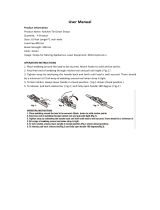
HIGH-CAPACITY TUBING BENDER
INS TRUCTI ONS
Item #21115

2 Eastwood Technical Assistance: 800.544.5118 >> techelp@eastwood.com
Your EASTWOOD HIGH-CAPACITY TUBING BENDER is a high quality, precision tool capable of creating accurate, smooth, kink-free bends up to 180°
in aluminum, steel, stainless steel and copper tubing, in sizes ranging from 3/4" to 2" with available Eastwood Die Sets. Build roll bars, shop fixtures,
go-kart frames and much more with high accuracy and professional results.
CONTENTS
(1) Lower Frame Plate (with M8 holes) - (A)
(1) Upper Frame Plate - (B)
(2) Frame Spacers, Ø 1" x 4" [Ø 26mm x 102mm] - (C)
(2) Frame Spacer Bolts, M18 x 180mm - (D)
(4) 18mm Washers - (E)
(3) M18 Nylon Locknuts - (F)
(2) Drive Links - (G)
(2) Ø 3/4" x 2-13/16" [Ø 19mm x 72mm] Drive Link Spacers - (H)
(4) 12mm Washers - ( I )
(2) M12 x 120mm Drive Link Bolts - (J)
(2) M12 Nylon Locknuts - (K)
(1) Ø 7/8" x 6-3/4" [Ø 22mm x 172mm] Drive Pin - (L)
(1) Ø 7/8" x 5-3/8" [Ø 22mm x 136 mm] Drive Pin - (M)
(2) Brass Flanged Bushings - (N)
(1) Ratchet - (O)
(1) Ratchet Lever - (P)
(1) M18 x 50mm Shoulder Bolt - (Q)
(1) Ø 1" x 6-1/2" [Ø 25mm x 165mm] Pivot Pin - (R)
(2) Shaft Collars with Set-Screws - (S)
(1) Spacer Plate - (T)
(1) Degree Plate - (U)
(2) M8 Degree Plate Bolts - (V)
(1) Flexible Pointer - (X)
(2) Ø 7/8" x 4" [Ø 22mm x 100mm] U-Strap Drive Pin - (Y)
(1) Ø 7/8" x 3" [Ø 22mm x 75mm] U-Strap Drive Pin - (Z)
A
B
C
U
T
S
R
Q
P
O
N
M
L
K
J
I
H
G
F
E
D
E
I
N
V
X
Y Z

SAFETY INFORMATION
DANGER indicates a hazardous situation which, if not avoided, will result in death or serious injury.
WARNING indicates a hazardous situation which, if not avoided, could result in death or serious injury.
CAUTION used with the safety alert symbol, indicates a hazardous situation which, if not avoided, could result in minor or moderate injury.
NOTICE is used to address practices not related to personal injury.
READ INSTRUCTIONS
Thoroughly read and understand this manual before using. Save for future reference.
PINCH & CUT HAZARD!
• This tool has leveraged rotating components that generate greatly amplified crushing and bending forces which can quickly cause
severe injury! Keep fingers and hands away from moving parts when operating.
• Handling sharp metal can cause serious cuts. Wear thick, well fitting work gloves to prevent cuts from handling sharp metal.
INJURY HAZARD!
• Tremendous external torque loads are placed on this Tubing Bender during operation. This tool cannot be operated without adequate
support or severe personal injury or property damage can occur if it should suddenly be become dislodged or moves while in use.
Before beginning ANY work with this tool, it is absolutely necessary that it be securely bolted to a properly anchored Eastwood #21116
Bender Stand or a heavy, sturdy, anchored workbench.
FALL HAZARD!
• Strenuous physical force may need to be applied to the Tubing Bender during use. Failure to ensure proper footing can quickly result
in a fall which could inflict serious personal injury or property damage. Always work in a clean, uncluttered environment.
• Be sure there is sufficient working room around the tool to allow for safe handling of various lengths of tubing.
INJURY & DAMAGE HAZARD!
• Excessive resistance while operating could indicate a defect with the workpiece material or broken or damaged Tubing Bender
components. To avoid injury, stop work immediately and inspect workpiece material for nicks, dents, welds, excessive scale or
remaining coatings. Clean or repair as necessary or discard and begin with a new piece. Also inspect Tubing Bender components
for looseness or damage.
To order parts and supplies: 800.345.1178 >> eastwood.com 3

ASSEMBLY
FRAME ASSEMBLY
1. Lay the Lower Frame Plate (A) on a clean, level work surface.
NOTE: The Lower Frame Plate has two M8 tapped holes which must be
placed downward toward the work surface (FIG 1).
2. Using a 4" block of wood or other suitable material, place it between the
Lower Frame Plate (A) and the Upper Frame Plate (B) for temporary support.
3. Find the two 18mm bolt/washer/Frame Spacer/nut assemblies and disas-
semble them. Place the two Ø 1" x 4" [Ø 26mm x 102mm] Frame Spacers (C)
between the Lower Frame Plate and the Upper Frame Plate (FIG 2).
4. Place an M18 x 120mm Bolt (D) with 18mm washer (E) through the 19mm
hole in the Upper Frame Plate, Frame Spacer and Lower Frame Plate. Place
an 18mm washer (E) over the bolt and thread on the M18 locknut (F) leaving
it only finger tight at this time. Repeat with 2nd 18mm bolt and Frame Spacer
leaving it only finger tight as well (FIG 2).
DRIVE LINK SUB-ASSEMBLY
1. Set one the two Drive Links (G) along their edges on a clean, level
work surface.
2. Find the two 12mm bolt/washer/Drive Link Spacer/nut assemblies and
disassemble them. Place the two Ø 3/4" x 2-13/16" [Ø 19mm x 72mm]
long Drive Link Spacers (H) between the two Drive Links (G) (FIG 2).
3. Add a 12mm washer ( I ) to an M12 x 120mm Bolt (J) then slip it through the
13mm hole in the upper Drive Link, through Drive Link Spacer (H) and lower
Drive Link (G). Place a 12mm washer ( I ) over the bolt and thread on the M12
nut (K) leaving it only finger tight at this time. Repeat with 2nd M12 Bolt (J)
and Drive Link Spacer (H) leaving it only finger tight as well.
4. Check for alignment: Temporarily Insert the two Ø 7/8" [Ø 22mm] polished
Drive Pins (L) & (M) through two of the four 22.5 diameter holes in both
Drive Links (G) to align them. Tighten both M12 Bolts (J) & M12 Locknuts (K)
then remove the Drive Pins.
5. Insert two Brass Flanged Bushings (N) with the smaller diameter offsets in
the large 32mm diameter holes and with the flanges located on the outer
sides of the Drive Links (FIG 3).
6. Set this Sub-assembly aside for installation to Frame.
4 Eastwood Technical Assistance: 800.544.5118 >> techelp@eastwood.com
PINCH & SHARP METAL HAZARD!
The Eastwood High-Capacity Tubing Bender consists of moderately heavy metal components which can present a hand/finger pinch hazard
and cause potentially serious injuries if dropped on feet. Avoid pinching hands while handling parts during assembly and wear thick, well fitting
work gloves to prevent cuts from handling sharp metal. The use of safety shoes is strongly recommended.
FIG. 1
FIG. 2
FIG. 3
A
✓
B
✓
L
D
C
A
✓
✓
✓
✓
U
✓
✓
✓
✓
✓
✓
✓
✓
U
G
N
K
K
G
N

RATCHET SUB-ASSEMBLY
1. Place the Ratchet (O) between the spread blades of the Ratchet Lever (P) as
shown in (FIG 4) then pass the short M18 x 2.5" [50mm] Shoulder Bolt (Q)
through the blades of the Ratchet Lever (P) and Ratchet (O). Thread on
M18 Nut (F) then tighten.
INSTALLING DRIVE LINK SUB-ASSEMBLY
1. Back off the two M18 nuts out to the ends of the M18 bolts and spread the
Upper and Lower Frame Plates (A) & (B) sufficiently to allow the large 32mm
diameter holes to slip over the previously installed Brass Bushings up to their
flanges (FIG 5).
2. Slip the larger Ø 1" x 6-1/2" [Ø 25mm x 165mm] Pivot Pin (R) through
both Bushings.
3. Pull the Upper and Lower Frame Plates together with the INNER bolt finger
tight leaving the outer M18 bolt and Ø 1" x 4" [Ø 26mm x 102mm] Frame
Spacer out for now (FIG 5).
INSTALLING RATCHET/LEVER SUB ASSEMBLY IN FRAME
1. Place the Ø 1” x 4” [Ø 26mm x 102mm] Frame Spacer through the holes in
the Ratchet/Lever Sub-Assembly and slip one each of the Shaft Collars (S)
on either side with the Ratchet/Lever Sub-Assembly centered on the Frame
Spacer (FIG 6). Tighten the set-screws of the Shaft Collars (S) with a 4mm
hex key.
2. Insert the entire Ratchet/Lever Sub-Assembly between the Upper and Lower
Frame Plates then slip the M18 bolt (D) through both Frame Plates and
Ratchet/Lever Sub-Assembly (FIG 7).
To order parts and supplies: 800.345.1178 >> eastwood.com 5
MOUNTING HAZARD!
Mounting to the optional Eastwood #21116 Bender Stand is
strongly recommended for proper operation and maximum
safety. If the unit is being attached to a properly and solidly
secured stand, do so now.
MOUNTING HAZARD!
Failure to properly assemble and mount the Bender Stand to a
floor can cause sudden loss of control and serious injuries.
Be sure all mounting bolts are securely tightened before use.
FIG. 4
FIG. 5
FIG. 6
FIG. 7
O
✓
✓
✓
Q
P
✓
✓
✓
✓
✓
✓
✓
C
B
A
G
N
N
✓
✓
✓
✓
✓
✓
✓
Q
F
S
O
P
S
C
✓
✓
✓
✓
✓
✓
✓
B
C
Q
P
O
F
A

6 Eastwood Technical Assistance: 800.544.5118 >> techelp@eastwood.com
1. When mounting the unit, the Spacer Plate (T) must be located between the
Lower Frame Plate (A) and mounting surface. This is necessary to allow full
Drive Pin projection through Plates (FIG 8).
2. Check for alignment: Temporarily Insert the Ø 7/8" x 6-3/4" [Ø 22mm x
172mm] polished Drive Pin (L) through the Ø 22.5 holes in both Frame
Plates to align them. Tighten both M12 bolts & nuts then remove the
Drive Pin (FIG 8).
3. The optional Bender Handle (#21129) may be installed over the Ratchet Lever
(P) at this time (FIG 9).
ATTACH DEGREE PLATE
1. Locate the Degree Plate (U) under the Lower Frame Plate, align the 2 holes in
the Degree Plate with those in the Lower Frame Plate and fasten with two M8
Bolts (V) (FIG 10).
FIG. 8
FIG. 9
USAGE HAZARD!
Sudden slippage of the Bender Handle during use can cause
serious injuries. Be sure the clamping bolts are securely
tightened before use.
FIG. 10
✓
B
✓
✓
✓
✓
L
A
T
# 21116
Stand
✓
U
✓
V
✓

To order parts and supplies: 800.345.1178 >> eastwood.com 7
INSTALLING DIES
NOTE: The Curved Dies (available separately), U-Straps and Followbars are sized as
a matched set each in accordance with a specific tubing size and are not included
with the High Capacity Tubing Bender.
1. Insert the selected Forming Die in the Frame with the curved edge facing
ratchet end and with the Clamp oriented toward the offset (FIG 11).
2. Slip the larger Ø 1" x 6-1/2" [Ø 25mm x 165mm] Pivot Pin (R) through the
Die pivot hole and both Bushings (FIG 11).
3. Place the corresponding sized U-Strap over the square offset block of the
Forming Die then, depending on the die size, add a Ø 7/8" x 4" [Ø 22mm x
100mm or 75mm] U-Strap Drive Pin (Y or Z) to locate it (FIG 12).
4. Set the corresponding sized Followbar between the Upper and Lower Frame
Plates then add the Ø 7/8" x 6-3/4" [Ø 22mm x 172mm] Drive Pin (L) in the
appropriate hole to retain it (FIG 12).
5. Rotate the Drive Link Assembly back as close to the frame as possible with-
out binding or jamming.
6. Drop the Ø 7/8" x 5-3/8" [Ø 22mm x 136 mm] Drive Pin (M) through the
hole in the outer die edge (closest to the U-Clamp) that aligns with one in the
Drive Link Assembly (FIG 12).
NOTE: If the Pivot Pin (R) is found to be stuck while performing a die change, loosen
both M8 Bolts, lift the Drive Link assembly to release weight and support it while
re-tightening M8 Bolts.
ATTACHING DEGREE POINTER
1. Thread the base of the Degree Pointer (X) into the M9 thread on the end of
the square offset block of the Die (FIG 12).
FIG. 11
FIG. 12
✓
R
✓
✓
✓
B
Die
A
✓
A
✓
✓
✓
✓
✓
✓
✓
✓
✓
R
X
Die
Drive
Pin
T
L
M
Die
Follow Bar
Die
U-Strap
# 21116
Stand

8 Eastwood Technical Assistance: 800.544.5118 >> techelp@eastwood.com
OPERATION
1. Slip the workpiece tube in place between the curved Die and Followbar then
place the U-Clamp over the outer side of the tube (FIG 13). Lightly tighten the
Retainer Bolt if needed.
NOTE: On thinner walled material, it may be helpful to place a small cut out
section of material being used between end of the Retainer Bolt and outer side
of workpiece tubing to avoid creating possible dents or damage.
2. Drop the Ø 7/8" x 5-3/8" [Ø 22mm x 136 mm] Drive Pin (M) through the hole
in the outer die edge (closest to the U-Clamp) that aligns with one in the Drive
Link Assembly (FIG 13).
3. Place the Ratchet with the Teeth completely engaging the Drive Sleeve of
the Drive Link Assembly (FIG 13).
4. Begin exerting pressure on the Bender Handle to take up any lash and
eliminate looseness then set the Pointer to indicate “0°” on the Degree
Plate (FIG 13).
PINCH HAZARD!
The Eastwood High-Capacity Tubing Bender exerts tremendous bending and crushing forces in operation which can present a hand/
finger pinch hazard and cause potentially serious injuries in a matter of seconds. Avoid moving parts while operating and wear thick,
well fitting work gloves to prevent cuts from handling sharp metal. The use of safety shoes is strongly recommended.
INJURY HAZARD!
It is strongly recommended to use the optional Eastwood # 21129 Bender Handle for safest operation. DO NOT use a Bender Handle
Extension longer than 3’ (1 meter) long or permanent damage to the Bender and or serious injury and property damage could occur.
If excessive force is required, stop work immediately and check material or tool for interference or damage. If any breakage or dam-
age to the Bender occurs, DO NOT USE until proper repairs are made.
INJURY HAZARD!
The Eastwood High-Capacity Tubing Bender was specifically designed to be operated by one person only. Never have one person
operate the lever while one handles the material workpiece or serious injury could occur.
INJURY & DAMAGE HAZARD!
Injury or property damage could occur from being struck by swinging Bender Handle Extension or workpiece material. Before begin-
ning work, be sure the surrounding work area is clear of obstructions or persons to accommodate the swing of the Bender Handle
Extension or long sections of workpiece material.
DAMAGE HAZARD!
The Eastwood High-Capacity Tubing Bender, as with many advanced metal working tools, requires a learning curve to become
proficient in its use. Plan on using a generous amount of practice material in order to achieve a “feel” for the tool and learn what
results to expect before attempting a finished piece.
In addition, it is strongly suggested that you create a set of “templates” to be made of each size, material, thickness and degree of
bend for every type of tubing you plan to use in your project. This will save a great deal of time and material waste as you progress
through future projects.
DAMAGE HAZARD!
Workpiece material must be clean of any rust, burrs, nicks, welds or coatings before attempting to bend or interference and binding
will occur.
DAMAGE HAZARD!
Apply a minimal amount of a light lubricant to material and die surfaces to ease bending process. Do not over lubricate.
INJURY & DAMAGE HAZARD!
Tremendous external torque loads are placed on this Tubing Bender during operation. This tool cannot be operated without adequate
support or severe personal injury or property damage can occur if it should suddenly be become dislodged or moves while in use.
Before beginning ANY work with this tool, it is absolutely necessary that it be securely bolted to a properly anchored Eastwood
#21116 Bender Stand or a heavy, sturdy, anchored workbench.
FIG. 13
✓
L
Die
U-Strap
✓
✓
✓
✓
✓
✓
Die
X
M
Die
Pin
R
Die
Follow Bar
✓

To order parts and supplies: 800.345.1178 >> eastwood.com 9
1. Slowly and steadily pull on the Bender Handle, bending the workpiece tubing
as you go.
2. When the Bender Handle is at the end of its travel, stop and very gently pull
it back several degrees releasing the Ratchet Teeth from the Drive Sleeve
(FIG 14).
3. Reposition the Ratchet so that Drive Teeth further down the Ratchet fully
engage the Drive Sleeve (FIG 15).
4. Once again, slowly and steadily pull on the Bender Handle, bending the
workpiece tubing as you go. When the Bender Handle at the end of its travel,
stop and very gently pull it back several degrees releasing the Ratchet Teeth
from the Drive Sleeve.
5. Once the entire usable length of the Ratchet has been reached and no more
bending range is available, the Ø 7/8" x 5-3/8" [Ø 22mm x 136 mm] Drive
Pin (M) must be pulled out and relocated in the Drive Link and further toward
the center of the Die (FIG 16).
NOTE: on average, the workpiece tubing will bend up to approximately
40° for each full travel length of the Ratchet).
6. To achieve more bending range; repeatedly pull the Drive Pin from the Curved
Die and Drive Link Assembly and move to another hole further inward on the
Die (FIG 17).
7. Once again, place the Ratchet with the Teeth completely engaging the Drive
Sleeve of the Drive Link Assembly.
8. As previously, slowly and steadily pull on the Bender Handle, bending the
workpiece tubing as you go. Watch the position of the Pointer on the Degree
Wheel as you approach your desired angle (FIG 17).
IMPORTANT NOTE: There will be a certain amount of “springback” meaning
that you must pull several degrees past your gauge target then allow it to
“spring back” to the final degree mark. This varies widely according to the
particular material, diameter and thickness. Chromoly and high carbon steel
will generally have more “springback” than milder steels and aluminum. This
is one reason that some “trial and error” must be performed to explore the
properties of the material before working on a final project piece.
FIG. 14
FIG. 15
FIG. 16
FIG. 17
TECH TIP:
Once you are familiar with the characteristics of the
Eastwood High-Capacity Tubing Bender and how it reacts with
your most commonly formed tubing sizes, materials and bend
amounts, it is a great idea to create a series of “Templates” that
you can use as a pattern. For example: if you frequently use
Ø 2” Chromoly steel tubing, you may want to create templates in
22.5°, 45°, 90°, 120° & 180° and more as needed. On these, mark
the amount of material required to make each bend and
the amount of “springback” encountered.

10 Eastwood Technical Assistance: 800.544.5118 >> techelp@eastwood.com
TUBING LAY OUT
The following mathematical formula may be applied for specific degrees of bend:
• Beginning with the value of the Bend Radius of the Die to be used, multiply it by 6.28.
• Next, multiply the value found by the planned degree of bend.
• Lastly, divide that value by 360.
• Also, be aware that an additional 4" of straight section per bend is required as it is clamped in the U-Strap.
THE FOLLOWING ARE SEVERAL EXAMPLES
If you plan to use a Die with a Bend Radius of 4” and make a 120° bend in it:
4" Bend Radius x 6.28 = 25.12.
25.12 x 120° = 3014.4
3014.4 / 360 = 8.38"
8.38" + 4" = 12.38"
For a Die with 6” Bend Radius and a 30° bend
6" Bend Radius x 6.28 = 38.28
38.28 x 30° = 1184.4
1184.4/360 = 3.19”
3.19" + 4” = 7.19"
As an alternative, we have provided a chart with the most common bend angles of 90° and 180°. This chart is intended to be used as an approximate “rule-of-
thumb” when laying out your project to help determine the amount of tubing needed.
NOTE: The following figures are representative of the average linear amount of tubing required for a given size and the bend radius it will yield @ 90° for 120°
Dies and @ 180° for 240° Dies. Please note the final tubing length is dependent upon the particular wall thickness, diameter and hardness of the tubing used.
These figures are for the Length of the bend portion only as measured at the centerline of the tubing. Remember to add 4” of clamping length.
Tubing Layout Length Chart
Die Tubing Size Die Bend Radius 90° 180°
3/4" 3" 4-3/4" 9-7/16"
1" 4" 6-5/16" 12-9 /16"
1-1/2" 5" 7-7/8" 15-3/4"
1-5/8" 5" 7-7/8" 15-3/4"
1-3/4" 6" 9-7/16" 18-7/8"
2" 6" 9-7/16" 18-7/8"

To order parts and supplies: 800.345.1178 >> eastwood.com 11
NOTES

© Copyright 2016 Easthill Group, Inc. 1/16 Instruction Item #21115Q Rev. 0
If you have any questions about the use of this product, please contact
The Eastwood Technical Assistance Service Department: 800.544.5118 >> email: techelp@eastwood.com
PDF version of this manual is available online >> eastwood.com/21115manual
The Eastwood Company 263 Shoemaker Road, Pottstown, PA 19464, USA
US and Canada: 800.345.1178 Outside US: 610.718.8335
Fax: 610.323.6268 eastwood.com
ADDITIONAL ITEMS
#21116 Bender Stand
#21129 Bender Handle
#21117 0.75" x 3" Radius, 120° Die
#21118 1.0" x 4" Radius, 120° Die
#21119 1.5" x 5" Radius, 120° Die
#21120 1.625" x 5" Radius, 120° Die
#21121 1.75" x 6" Radius, 120° Die
#21122 2" x 6" Radius, 120° Die
#21123 0.75" x 3" Radius, 240° Die
#21124 1.0" x 4" Radius, 240° Die
#21125 1.5" x 5" Radius, 240° Die
#21126 1.625" x 5" Radius, 240° Die
#21127 1.75" x 6" Radius, 240° Die
/