
Latitude 5320
Service Manual
Regulatory Model: P138G/P139G
Regulatory Type: P138G001/P139G001
January 2021
Rev. A00

Notes, cautions, and warnings
NOTE: A NOTE indicates important information that helps you make better use of your product.
CAUTION: A CAUTION indicates either potential damage to hardware or loss of data and tells you how to avoid
the problem.
WARNING: A WARNING indicates a potential for property damage, personal injury, or death.
© 2021 Dell Inc. or its subsidiaries. All rights reserved. Dell, EMC, and other trademarks are trademarks of Dell Inc. or its subsidiaries. Other
trademarks may be trademarks of their respective owners.

Chapter 1: Working on your computer........................................................................................... 6
Safety instructions.............................................................................................................................................................. 6
Working inside your computer.................................................................................................................................... 6
After working inside your computer........................................................................................................................ 10
Chapter 2: Removing and installing components.......................................................................... 12
Recommended tools..........................................................................................................................................................12
Screw list..............................................................................................................................................................................12
Major components of your system................................................................................................................................ 15
SIM card tray...................................................................................................................................................................... 16
Removing the SIM card tray......................................................................................................................................16
Installing the SIM card tray........................................................................................................................................ 17
MicroSD card...................................................................................................................................................................... 18
Removing the micro-SD card.................................................................................................................................... 18
Installing the micro-SD card...................................................................................................................................... 19
Base cover.......................................................................................................................................................................... 20
Removing the base cover..........................................................................................................................................20
Installing the base cover.............................................................................................................................................21
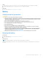
Battery................................................................................................................................................................................. 23
Lithium-ion battery precautions...............................................................................................................................23
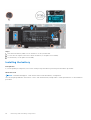
Removing the battery.................................................................................................................................................23
Installing the battery...................................................................................................................................................24
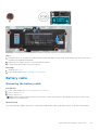
Battery cable...................................................................................................................................................................... 25
Removing the battery cable......................................................................................................................................25
Installing the battery cable........................................................................................................................................26
WLAN card..........................................................................................................................................................................27
Removing the WLAN card......................................................................................................................................... 27
Installing the WLAN card........................................................................................................................................... 28
WWAN card........................................................................................................................................................................ 29
Removing the WWAN card....................................................................................................................................... 29
Installing the WWAN card......................................................................................................................................... 30
Solid-state drive................................................................................................................................................................. 31
Removing the M.2 2280 solid-state drive..............................................................................................................31
Installing the M.2 2280 solid-state drive............................................................................................................... 32
Removing the M.2 2230 solid-state drive............................................................................................................. 33
Installing the M.2 2230 solid-state drive............................................................................................................... 34
Replacing the SSD securing rod.............................................................................................................................. 35
Speakers.............................................................................................................................................................................. 36
Removing the speakers..............................................................................................................................................36
Installing the speakers................................................................................................................................................ 37
Fan........................................................................................................................................................................................ 39
Removing the fan........................................................................................................................................................ 39
Installing the fan.......................................................................................................................................................... 40
Heat sink.............................................................................................................................................................................. 41
Contents
Contents 3

Removing the heatsink............................................................................................................................................... 41
Installing the heatsink................................................................................................................................................. 42
System board..................................................................................................................................................................... 42
Removing the system board..................................................................................................................................... 42
Installing the system board....................................................................................................................................... 44
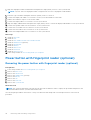
Power button with fingerprint reader (optional).......................................................................................................46
Removing the power button with fingerprint reader (optional)...................................................................... 46
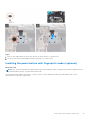
Installing the power button with fingerprint reader (optional).........................................................................47
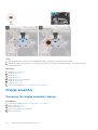
Display assembly................................................................................................................................................................48
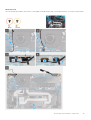
Removing the display assembly (laptop)............................................................................................................... 48
Installing the display assembly (laptop).................................................................................................................. 51
Removing the display assembly (2-in-1)................................................................................................................ 53
Installing the display assembly (2-in-1).................................................................................................................. 55
Display bezel....................................................................................................................................................................... 57
Removing the display bezel.......................................................................................................................................57
Installing the display bezel.........................................................................................................................................59
Display panel.......................................................................................................................................................................60
Removing the display panel...................................................................................................................................... 60
Installing the display panel.........................................................................................................................................63
Display hinges.....................................................................................................................................................................66
Removing the display hinges.................................................................................................................................... 66
Installing the display hinges.......................................................................................................................................67
Display back cover assembly.......................................................................................................................................... 68
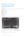
Removing the display back-cover........................................................................................................................... 68
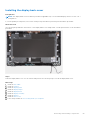
Installing the display back-cover............................................................................................................................. 69
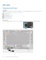
eDP cable............................................................................................................................................................................ 70
Removing the eDP cable............................................................................................................................................70
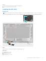
Installing the eDP cable...............................................................................................................................................71
Sensor board.......................................................................................................................................................................72
Removing the sensor board...................................................................................................................................... 72
Installing the sensor board........................................................................................................................................ 73
LED board............................................................................................................................................................................73
Removing the LED board........................................................................................................................................... 73
Installing the LED board............................................................................................................................................. 74
Camera.................................................................................................................................................................................75
Removing the camera.................................................................................................................................................75
Installing the camera................................................................................................................................................... 76
Removing the infrared camera................................................................................................................................. 77
Installing the infrared camera................................................................................................................................... 78
Smart card reader............................................................................................................................................................. 79
Removing the smart card reader (optional)..........................................................................................................79
Installing the smart card reader (optional)............................................................................................................80
Keyboard............................................................................................................................................................................. 82
Removing the keyboard............................................................................................................................................. 82
Installing the keyboard............................................................................................................................................... 84
SIM card slot filler............................................................................................................................................................. 87
Removing the SIM card slot filler............................................................................................................................ 87
Installing the SIM card slot filler...............................................................................................................................87
Palm-rest and keyboard assembly................................................................................................................................ 88
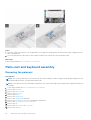
Removing the palmrest.............................................................................................................................................. 88
4
Contents

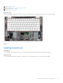
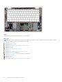
Installing the palm-rest.............................................................................................................................................. 89
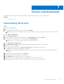
Chapter 3: Drivers and downloads................................................................................................91
Downloading the drivers...................................................................................................................................................91
Chapter 4: System setup............................................................................................................. 92
BIOS overview................................................................................................................................................................... 92
Entering BIOS setup program........................................................................................................................................ 92
Navigation keys..................................................................................................................................................................92
Boot Sequence...................................................................................................................................................................93
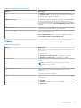
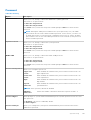
BIOS setup.......................................................................................................................................................................... 93
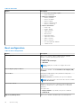
Overview....................................................................................................................................................................... 93
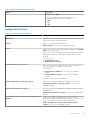
Boot configuration...................................................................................................................................................... 94
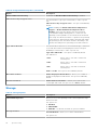
Integrated Devices...................................................................................................................................................... 95
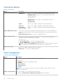
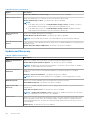
Storage.......................................................................................................................................................................... 96
Display............................................................................................................................................................................ 97
Connection options..................................................................................................................................................... 98
Power management....................................................................................................................................................98
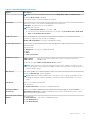
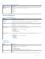
Security........................................................................................................................................................................ 100
Password...................................................................................................................................................................... 101
Update and Recovery............................................................................................................................................... 102
System management................................................................................................................................................ 103
Keyboard...................................................................................................................................................................... 103
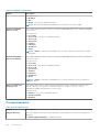
Pre-boot behavior......................................................................................................................................................104
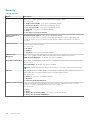
Virtualization support................................................................................................................................................105
Performance............................................................................................................................................................... 105
System logs................................................................................................................................................................. 106
System and setup password......................................................................................................................................... 107
Assigning a system setup password......................................................................................................................107
Deleting or changing an existing system setup password............................................................................... 107
Chapter 5: Troubleshooting....................................................................................................... 109
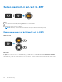
Built-in self-test (BIST)................................................................................................................................................. 109
System board built-in self-test (M-BIST).................................................................................................................. 110
Display panel power rail built-in self-test (L-BIST)............................................................................................ 110
Display panel power rail built-in self-test (L-BIST)...................................................................................................111
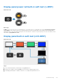
Display panel built-in self-test (LCD-BIST)................................................................................................................ 111
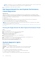
Dell SupportAssist Pre-boot System Performance Check diagnostics...............................................................112
Running the SupportAssist Pre-Boot System Performance Check............................................................... 112
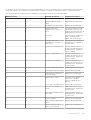
System diagnostic lights................................................................................................................................................. 112
Recovering the operating system.................................................................................................................................114
Flashing BIOS (USB key)................................................................................................................................................ 114
Flashing the BIOS............................................................................................................................................................. 114
WiFi power cycle.............................................................................................................................................................. 115
Flea power release........................................................................................................................................................... 115
Chapter 6: Getting help and contacting Dell............................................................................... 116
Contents
5

Working on your computer
Topics:
• Safety instructions
Safety instructions
Use the following safety guidelines to protect your computer from potential damage and to ensure your personal safety. Unless
otherwise noted, each procedure included in this document assumes that you have read the safety information that shipped
with your computer.
WARNING: Before working inside your computer, read the safety information that is shipped with your
computer. For more safety best practices, see the Regulatory Compliance home page at www.dell.com/
regulatory_compliance.
WARNING: Disconnect your computer from all power sources before opening the computer cover or panels.
After you finish working inside the computer, replace all covers, panels, and screws before connecting your
computer to an electrical outlet.
CAUTION: To avoid damaging the computer, ensure that the work surface is flat, dry, and clean.
CAUTION: To avoid damaging the components and cards, handle them by their edges, and avoid touching the
pins and the contacts.
CAUTION: You should only perform troubleshooting and repairs as authorized or directed by the Dell technical
assistance team. Damage due to servicing that is not authorized by Dell is not covered by your warranty. See the
safety instructions that is shipped with the product or at www.dell.com/regulatory_compliance.
CAUTION: Before touching anything inside your computer, ground yourself by touching an unpainted metal
surface, such as the metal at the back of the computer. While you work, periodically touch an unpainted metal
surface to dissipate static electricity which could harm internal components.
CAUTION: When you disconnect a cable, pull it by its connector or its pull tab, not the cable itself. Some cables
have connectors with locking tabs or thumbscrews that you must disengage before disconnecting the cable.
When disconnecting cables, keep them evenly aligned to avoid bending the connector pins. When connecting
cables, ensure that the ports and the connectors are correctly oriented and aligned.
CAUTION: Press and eject any installed card from the media-card reader.
NOTE: The color of your computer and certain components may appear differently than shown in this document.
Working inside your computer
Before working inside your computer
About this task
NOTE: The images in this document may differ from your computer depending on the configuration you ordered.
1
6 Working on your computer

Steps
1. Save and close all open files and exit all open applications.
2. Shut down your computer. Click Start > Power > Shut down.
NOTE: If you are using a different operating system, see the documentation of your operating system for shut-down
instructions.
3. Disconnect your computer and all attached devices from their electrical outlets.
4. Disconnect all attached network devices and peripherals, such as keyboard, mouse, and monitor from your computer.
CAUTION: To disconnect a network cable, first unplug the cable from your computer and then unplug the
cable from the network device.
5. Remove any media card and optical disc from your computer, if applicable.
Electrostatic discharge—ESD protection
ESD is a major concern when you handle electronic components, especially sensitive components such as expansion cards,
processors, memory DIMMs, and system boards. Very slight charges can damage circuits in ways that may not be obvious, such
as intermittent problems or a shortened product life span. As the industry pushes for lower power requirements and increased
density, ESD protection is an increasing concern.
Due to the increased density of semiconductors used in recent Dell products, the sensitivity to static damage is now higher than
in previous Dell products. For this reason, some previously approved methods of handling parts are no longer applicable.
Two recognized types of ESD damage are catastrophic and intermittent failures.
● Catastrophic – Catastrophic failures represent approximately 20 percent of ESD-related failures. The damage causes
an immediate and complete loss of device functionality. An example of catastrophic failure is a memory DIMM that has
received a static shock and immediately generates a "No POST/No Video" symptom with a beep code emitted for missing or
nonfunctional memory.
● Intermittent – Intermittent failures represent approximately 80 percent of ESD-related failures. The high rate of
intermittent failures means that most of the time when damage occurs, it is not immediately recognizable. The DIMM
receives a static shock, but the tracing is merely weakened and does not immediately produce outward symptoms related to
the damage. The weakened trace may take weeks or months to melt, and in the meantime may cause degradation of memory
integrity, intermittent memory errors, etc.
The more difficult type of damage to recognize and troubleshoot is the intermittent (also called latent or "walking wounded")
failure.
Perform the following steps to prevent ESD damage:
● Use a wired ESD wrist strap that is properly grounded. The use of wireless anti-static straps is no longer allowed; they do not
provide adequate protection. Touching the chassis before handling parts does not ensure adequate ESD protection on parts
with increased sensitivity to ESD damage.
● Handle all static-sensitive components in a static-safe area. If possible, use anti-static floor pads and workbench pads.
● When unpacking a static-sensitive component from its shipping carton, do not remove the component from the anti-static
packing material until you are ready to install the component. Before unwrapping the anti-static packaging, ensure that you
discharge static electricity from your body.
● Before transporting a static-sensitive component, place it in an anti-static container or packaging.
ESD field service kit
The unmonitored Field Service kit is the most commonly used service kit. Each Field Service kit includes three main components:
anti-static mat, wrist strap, and bonding wire.
Components of an ESD field service kit
The components of an ESD field service kit are:
● Anti-Static Mat – The anti-static mat is dissipative and parts can be placed on it during service procedures. When using an
anti-static mat, your wrist strap should be snug and the bonding wire should be connected to the mat and to any bare metal
on the system being worked on. Once deployed properly, service parts can be removed from the ESD bag and placed directly
on the mat. ESD-sensitive items are safe in your hand, on the ESD mat, in the system, or inside a bag.
Working on your computer
7

● Wrist Strap and Bonding Wire – The wrist strap and bonding wire can be either directly connected between your wrist
and bare metal on the hardware if the ESD mat is not required, or connected to the anti-static mat to protect hardware that
is temporarily placed on the mat. The physical connection of the wrist strap and bonding wire between your skin, the ESD
mat, and the hardware is known as bonding. Use only Field Service kits with a wrist strap, mat, and bonding wire. Never
use wireless wrist straps. Always be aware that the internal wires of a wrist strap are prone to damage from normal wear
and tear, and must be checked regularly with a wrist strap tester in order to avoid accidental ESD hardware damage. It is
recommended to test the wrist strap and bonding wire at least once per week.
● ESD Wrist Strap Tester – The wires inside of an ESD strap are prone to damage over time. When using an unmonitored
kit, it is a best practice to regularly test the strap prior to each service call, and at a minimum, test once per week. A
wrist strap tester is the best method for doing this test. If you do not have your own wrist strap tester, check with your
regional office to find out if they have one. To perform the test, plug the wrist-strap's bonding-wire into the tester while it is
strapped to your wrist and push the button to test. A green LED is lit if the test is successful; a red LED is lit and an alarm
sounds if the test fails.
● Insulator Elements – It is critical to keep ESD sensitive devices, such as plastic heat sink casings, away from internal parts
that are insulators and often highly charged.
● Working Environment – Before deploying the ESD Field Service kit, assess the situation at the customer location. For
example, deploying the kit for a server environment is different than for a desktop or portable environment. Servers are
typically installed in a rack within a data center; desktops or portables are typically placed on office desks or cubicles. Always
look for a large open flat work area that is free of clutter and large enough to deploy the ESD kit with additional space to
accommodate the type of system that is being repaired. The workspace should also be free of insulators that can cause an
ESD event. On the work area, insulators such as Styrofoam and other plastics should always be moved at least 12 inches or
30 centimeters away from sensitive parts before physically handling any hardware components
● ESD Packaging – All ESD-sensitive devices must be shipped and received in static-safe packaging. Metal, static-shielded
bags are preferred. However, you should always return the damaged part using the same ESD bag and packaging that the
new part arrived in. The ESD bag should be folded over and taped shut and all the same foam packing material should be
used in the original box that the new part arrived in. ESD-sensitive devices should be removed from packaging only at an
ESD-protected work surface, and parts should never be placed on top of the ESD bag because only the inside of the bag is
shielded. Always place parts in your hand, on the ESD mat, in the system, or inside an anti-static bag.
● Transporting Sensitive Components – When transporting ESD sensitive components such as replacement parts or parts
to be returned to Dell, it is critical to place these parts in anti-static bags for safe transport.
ESD protection summary
It is recommended that all field service technicians use the traditional wired ESD grounding wrist strap and protective anti-static
mat at all times when servicing Dell products. In addition, it is critical that technicians keep sensitive parts separate from all
insulator parts while performing service and that they use anti-static bags for transporting sensitive components.
Transporting sensitive components
When transporting ESD sensitive components such as replacement parts or parts to be returned to Dell, it is critical to place
these parts in anti-static bags for safe transport.
Service mode
Service Mode allows users to immediately cut off electricity from the system and conduct repairs without disconnecting the
battery cable from the system board:
To enter the Service Mode:
1. Shut down the system and disconnect the AC adapter from the system.
2. Hold <B> key on the keyboard press the power button for 3 seconds until the Dell logo appears on the screen. The system
boots.
8
Working on your computer

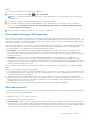
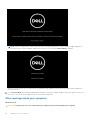
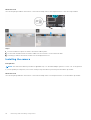
3. The following screen appears.
Press any key to continue.
NOTE:
The Service Mode procedure automatically skips this step if the Owner Tag of the system is not set up in
advance by the manufacturer.
4. When the ready-to-proceed message appears on the screen, press any key to proceed. The system emits three short beeps
and shuts down immediately.
Working on your computer
9

NOTE: If the AC adapter has not been disconnected, a message prompting you to remove the AC adapter appears on
the screen. Remove the AC adapter and then press any key to continue the Service Mode procedure.
Once the system shuts down, you can perform the replacement procedures without disconnecting the battery cable from
the system board.
5. To exit Service Mode after finishing replacement procedures, connect AC adapter and press the power button to power on
the system. The system automatically returns to normal functioning mode.
After working inside your computer
About this task
CAUTION: Leaving stray or loose screws inside your computer may severely damage your computer.
10 Working on your computer

Steps
1. Replace all screws and ensure that no stray screws remain inside your computer.
2. Connect any external devices, peripherals, or cables you removed before working on your computer.
3. Replace any media cards, discs, or any other parts that you removed before working on your computer.
4. Connect your computer and all attached devices to their electrical outlets.
5. Turn on your computer.
Working on your computer 11

Removing and installing components
NOTE: The images in this document may differ from your computer depending on the configuration you ordered.
Topics:
• Recommended tools
• Screw list
• Major components of your system
• SIM card tray
• MicroSD card
• Base cover
• Battery
• Battery cable
• WLAN card
• WWAN card
• Solid-state drive
• Speakers
• Fan
• Heat sink
• System board
• Power button with fingerprint reader (optional)
• Display assembly
• Display bezel
• Display panel
• Display hinges
• Display back cover assembly
• eDP cable
• Sensor board
• LED board
• Camera
• Smart card reader
• Keyboard
• SIM card slot filler
• Palm-rest and keyboard assembly
Recommended tools
The procedures in this document may require the following tools:
● Phillips #0 screwdriver
● Plastic scribe
NOTE: The #0 screw driver is for screws 0-1, and the #1 screw driver is for screws 2-4.
Screw list
NOTE:
When removing screws from a component, it is recommended to note the screw type, the quantity of screws, and
then place them in a screw storage box. This is to ensure that the correct number of screws and correct screw type is
restored when the component is replaced.
2
12 Removing and installing components

NOTE: Some computers have magnetic surfaces. Ensure that the screws are not left attached to such surface when
replacing a component.
NOTE: Screw color may vary with the configuration ordered.
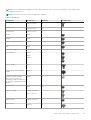
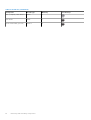
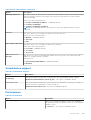
Table 1. Screw list
Component Screw type Quantity Screw image
Base cover
Captive screws 8
3-cell battery
Captive screws 4
4-cell battery
Captive screws
4
WLAN M2x3 1
WWAN M2x3 1
Solid-state drive bracket M2x2.5 2
Fan M2x3 2
Heat sink - UMA only Captive screws 4
System board M2x3
M2x4
M2x2.5
2
1
2
Type-C bracket M2x5 3
Power button with fingerprint
reader
M2x2.5 1
Fingerprint reader bracket
Note: Systems with non-
fingerprint reader configuration
do not have a fingerprint reader
bracket.
M2x4 1
Keyboard
M2x2 19
Display assembly
Laptop - M2.5x4
2-in-1 - M2.5x4
4
4
Display panel
Laptop - M2x2.5 2
Hinge screws
M2.5x3 6
Removing and installing components 13

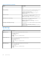
Table 1. Screw list (continued)
Component Screw type Quantity Screw image
eDP (or display) cable bracket
M2x4 1
LED board M2x3 1
Smart card reader (optional) M2x2.5 2
14 Removing and installing components

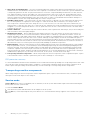
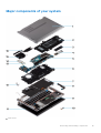
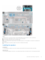
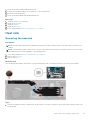
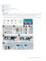
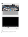
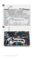
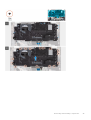
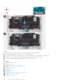
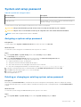
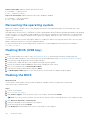
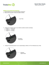
Major components of your system
1. Base cover
Removing and installing components
15

2. Battery
3. SSD thermal plate
4. M.2 2280 SSD card
5. System board
6. Keyboard bracket
7. Keyboard
8. Speakers
9. Palm-rest assembly
10. LED board
11. Display panel
12. Power button with fingerprint reader (optional)
13. WLAN
14. WWAN
15. Fan
16. Heat sink
NOTE: Dell provides a list of components and their part numbers for the original system configuration purchased. These
parts are available according to warranty coverages purchased by the customer. Contact your Dell sales representative for
purchase options.
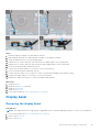
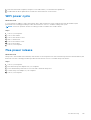
SIM card tray
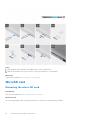
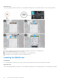
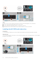
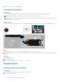
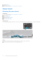
Removing the SIM card tray
Prerequisites
Follow the procedure in before working inside your computer.
About this task
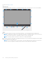
The following image provides a visual representation of the SIM card tray removal procedure.
16
Removing and installing components

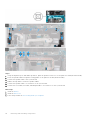
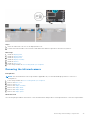
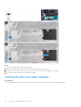
Steps
1. Insert a pin into the release hole to release the SIM card tray.
2. Push the pin to disengage the lock, and eject the SIM card tray.
3. Slide the SIM card tray out of the slot on the system.
4. Remove the SIM card from the SIM card tray.
5. Slide and push the SIM card tray back into the slot.
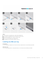
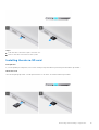
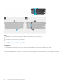
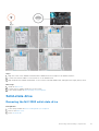
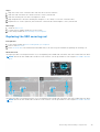
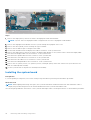
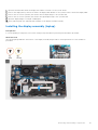
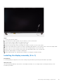
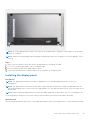
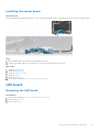
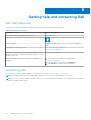
Installing the SIM card tray
Prerequisites
If you are replacing a component, remove the necessary component before the installation procedure.
About this task
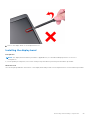
The following image provides a visual representation of the SIM card tray installation procedure.
Removing and installing components
17

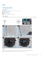
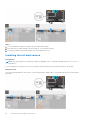
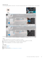
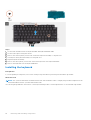
Steps
1. Align and place the SIM card in the dedicated slot on the SIM card tray.
2. Slide the SIM card tray into the slot in the system [6], and push it to lock in place.
Next steps
Follow the procedure in After working on your computer.
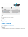
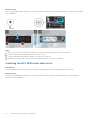
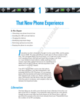
MicroSD card
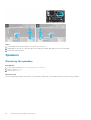
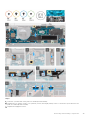
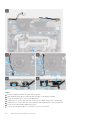
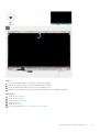
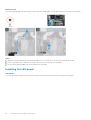
Removing the micro-SD card
Prerequisites
Follow the procedure in before working inside your computer.
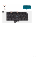
About this task
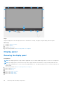
The following image provides a visual representation of the micro-SD card removal procedure.
18
Removing and installing components

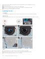
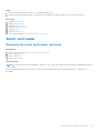
Steps
1. Push the micro-SD card to eject it from the slot.
2. Remove the micro-SD card from the system.
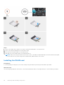
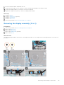
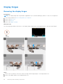
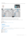
Installing the micro-SD card
Prerequisites
If you are replacing a component, remove the existing component before performing the installation procedure.
About this task
The following image provides a visual representation of the micro-SD card installation procedure.
Removing and installing components
19

Steps
Insert the micro-SD card into its slot until it clicks into place.
Next steps
1. Follow the procedure in After working on your computer.
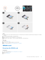
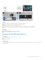
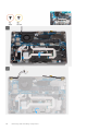
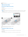
Base cover
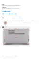
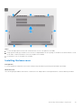
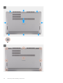
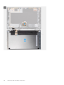
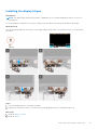
Removing the base cover
Prerequisites
1. Follow the procedure in before working inside your computer.
About this task
The following images indicate the location of the base cover and provide a visual representation of the removal procedure.
20 Removing and installing components
Page is loading ...
Page is loading ...
Page is loading ...
Page is loading ...
Page is loading ...
Page is loading ...
Page is loading ...
Page is loading ...
Page is loading ...
Page is loading ...
Page is loading ...
Page is loading ...
Page is loading ...
Page is loading ...
Page is loading ...
Page is loading ...
Page is loading ...
Page is loading ...
Page is loading ...
Page is loading ...
Page is loading ...
Page is loading ...
Page is loading ...
Page is loading ...
Page is loading ...
Page is loading ...
Page is loading ...
Page is loading ...
Page is loading ...
Page is loading ...
Page is loading ...
Page is loading ...
Page is loading ...
Page is loading ...
Page is loading ...
Page is loading ...
Page is loading ...
Page is loading ...
Page is loading ...
Page is loading ...
Page is loading ...
Page is loading ...
Page is loading ...
Page is loading ...
Page is loading ...
Page is loading ...
Page is loading ...
Page is loading ...
Page is loading ...
Page is loading ...
Page is loading ...
Page is loading ...
Page is loading ...
Page is loading ...
Page is loading ...
Page is loading ...
Page is loading ...
Page is loading ...
Page is loading ...
Page is loading ...
Page is loading ...
Page is loading ...
Page is loading ...
Page is loading ...
Page is loading ...
Page is loading ...
Page is loading ...
Page is loading ...
Page is loading ...
Page is loading ...
Page is loading ...
Page is loading ...
Page is loading ...
Page is loading ...
Page is loading ...
Page is loading ...
Page is loading ...
Page is loading ...
Page is loading ...
Page is loading ...
Page is loading ...
Page is loading ...
Page is loading ...
Page is loading ...
Page is loading ...
Page is loading ...
Page is loading ...
Page is loading ...
Page is loading ...
Page is loading ...
Page is loading ...
Page is loading ...
Page is loading ...
Page is loading ...
Page is loading ...
Page is loading ...
-
 1
1
-
 2
2
-
 3
3
-
 4
4
-
 5
5
-
 6
6
-
 7
7
-
 8
8
-
 9
9
-
 10
10
-
 11
11
-
 12
12
-
 13
13
-
 14
14
-
 15
15
-
 16
16
-
 17
17
-
 18
18
-
 19
19
-
 20
20
-
 21
21
-
 22
22
-
 23
23
-
 24
24
-
 25
25
-
 26
26
-
 27
27
-
 28
28
-
 29
29
-
 30
30
-
 31
31
-
 32
32
-
 33
33
-
 34
34
-
 35
35
-
 36
36
-
 37
37
-
 38
38
-
 39
39
-
 40
40
-
 41
41
-
 42
42
-
 43
43
-
 44
44
-
 45
45
-
 46
46
-
 47
47
-
 48
48
-
 49
49
-
 50
50
-
 51
51
-
 52
52
-
 53
53
-
 54
54
-
 55
55
-
 56
56
-
 57
57
-
 58
58
-
 59
59
-
 60
60
-
 61
61
-
 62
62
-
 63
63
-
 64
64
-
 65
65
-
 66
66
-
 67
67
-
 68
68
-
 69
69
-
 70
70
-
 71
71
-
 72
72
-
 73
73
-
 74
74
-
 75
75
-
 76
76
-
 77
77
-
 78
78
-
 79
79
-
 80
80
-
 81
81
-
 82
82
-
 83
83
-
 84
84
-
 85
85
-
 86
86
-
 87
87
-
 88
88
-
 89
89
-
 90
90
-
 91
91
-
 92
92
-
 93
93
-
 94
94
-
 95
95
-
 96
96
-
 97
97
-
 98
98
-
 99
99
-
 100
100
-
 101
101
-
 102
102
-
 103
103
-
 104
104
-
 105
105
-
 106
106
-
 107
107
-
 108
108
-
 109
109
-
 110
110
-
 111
111
-
 112
112
-
 113
113
-
 114
114
-
 115
115
-
 116
116


Ask a question and I''ll find the answer in the document
Finding information in a document is now easier with AI
Related papers
-
Dell Latitude 7380 User guide
-
Dell Inspiron 7500 User manual
-
Dell OptiPlex 5080 Owner's manual
-
-
Dell Inspiron 7300 User manual
-
Dell Inspiron 7501 User manual
-
Dell latitude e5270 Owner's manual
-
-
Dell Precision 3561 Owner's manual
-
Dell Latitude 5521 Owner's manual
Other documents
-
Alienware m15 R3 User manual
-
Alienware m15 Ryzen Edition R5 User manual
-
Alienware m15 R4 User manual
-
ASROCK 13.3 Inch Side Panel Kit User manual
-
Getac V100(791901250XXX) User guide
-
 Wiley 978-1-1180-7601-9 Datasheet
-
Toshiba 6100 User manual
-
-
-
 TrickleStar TS2602 User guide

