
MCU-30 Family User Manual
Mobilicom LTD
Hametzoda 31, Azor - Israel
Phone: +972-77-7103060 - Fax: +972-77-7103060 - www.mobilicom.com

MCU-30 User Manual
Page : 2 / 51
This page contains information which is protected by copyright and is proprietary to Mobilicom Ltd.
No part of this document may be used, copied, disclosed or conveyed to another party without prior written consent of Mobilicom Ltd
Notice
This manual contains information that is proprietary of Mobilicom Ltd.
No part of this publication may be reproduced in any form whatsoever without prior
written approval by Mobilicom.
License Terms
Mobilicom hereby grants a non-exclusive, nontransferable worldwide license to the
licensee of this software product to use and install Mobilicom's MC-EMA software, in
object code only for the sole and internal purpose of configuring, monitoring and
managing Mobilicom's MCU’s.
Warranty
Mobilicom does not warrant that this software product is free from errors and/or will
run properly on all computer hardware and/or operating systems. Mobilicom does not
warrant that this software will operate in the combinations which may be selected for
use by end users or that the operation of this software product will be uninterrupted
or error free.
Limitation of Liability
Mobilicom’s cumulative liability to you or any other party for any loss or damages
resulting from any claims, demands, or actions arising out of or relating to this
agreement and the MC-EMA shall not exceed the sum paid to Mobilicom for the
purchase of the MC-EMA. In no event shall Mobilicom be liable for any indirect,
incidental, consequential, special or exemplary damages or lost profits, even if
Mobilicom has been advised of the possibility of such damages.
This agreement shall be construed and governed in accordance with the laws of the
State of Israel.

MCU-30 User Manual
Page : 3 / 51
This page contains information which is protected by copyright and is proprietary to Mobilicom Ltd.
No part of this document may be used, copied, disclosed or conveyed to another party without prior written consent of Mobilicom Ltd
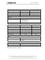
Document Information
Date
Version
Author(s)
Reference
Distribution
Comments
06.05.13
1.0
Tomer Hot
External
Release
19.12.13
1.1
Tomer Hot
External
LED functionality
17.2.14
1.2
Tomer Hot
External
Added PTMP
4.6.14
1.3
Tomer Hot
External
Configuration changes
21.10.14
1.4
Tomer Hot
External
Updates
12.01.15
1.5
Tomer Hot
External
Update of product images
2.04.15
1.6
Tomer Hot
External
Added Collaborative MESH
27.08.15
1.7
Tomer Hot
External
Datasheet updates
14.06.16
1.8
Tomer Hot
External
Added Lite unit phase 1
28.08.17
1.8.1
Tomer Hot
External
Added FCC Statement
28.01.18
1.8.2
Boaz Pick
External
Changes for FCC
29-1-2018
1.8.3
Boaz Pick
External
Change per FCC Request
14-2-2018
1.8.4
Boaz Pick
External
Section 6.1.2 , Antenna
type +Declaration of
Conformity
06-9-2018
1.8.5
Tomer Hot
External
FCC 915MHz update
Revision History
Section
Change
Revision
All
Changed Images
1.5
Section 10
Added
1.6
Appendix A
Updated Datasheet
1.7
Section 4.2, 5
Appex A, B, C
Added Lite info/drawings
1.8
Added FCC Statement; Removed confidential statement
1.8.1
Typos fixing
1.8.2
Sections: 6.1.3,
13 and 15.1
Remove Optional statements
1.8.3
6.1.2, 13, p51
Antenna Type Dipole
1.8.4
Appex A
1.8.5

MCU-30 User Manual
Page : 4 / 51
This page contains information which is protected by copyright and is proprietary to Mobilicom Ltd.
No part of this document may be used, copied, disclosed or conveyed to another party without prior written consent of Mobilicom Ltd
Contents
1 QUICK START GUIDE ........................................................................................ 8
2 INTRODUCTION ................................................................................................. 9
2.1 ABBREVIATION LIST ......................................................................................... 9
3 OVERVIEW ....................................................................................................... 12
3.1 NETWORK TOPOLOGIES AND APPLICATIONS .................................................... 13
3.1.1 Mobile Point-to-Point (PTP)................................................................. 13
3.1.2 Mobile MESH - Multi-Point-to-Multi-Point (MPTMP) ............................ 13
3.1.3 Collaborative MESH – Collaborative Relay ......................................... 13
3.2 MCU-30 MAIN FEATURES ............................................................................. 14
3.3 PACKETS SUPPORTED BY THE MOBILICOM NETWORK ....................................... 14
4 PHYSICAL DESCRIPTION ............................................................................... 15
4.1 FRONT VIEW CONNECTORS ........................................................................... 15
4.2 REAR VIEW CONNECTORS ............................................................................. 16
5 MECHANICAL SPECIFICATIONS ................................................................... 19
6 TECHNICAL SPECIFICATIONS ....................................................................... 19
6.1 RADIO AND MODEM SPECIFICATIONS .............................................................. 19
6.1.1 Frequency bands available with the MCU-30: ..................................... 19
6.1.2 Antennas ............................................................................................. 19
6.1.3 RF Characteristics ............................................................................... 20
6.2 POWER SPECIFICATIONS ............................................................................... 21
6.3 ENVIRONMENTAL SPECIFICATIONS ................................................................. 21
6.4 EMBEDDED GPS CHARACTERISTICS .............................................................. 22
7 TDMA ................................................................................................................ 23
8 MOBILE PTP (POINT-TO-POINT) .................................................................... 23
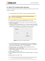
8.1 MOBILE PTP LINK STEP-BY-STEP CONFIGURATION ......................................... 24
8.2 MCU-30 LED INDICATOR .............................................................................. 25
9 MOBILE MESH (MULTI-POINT-TO- MULTI-POINT) NETWORK .................... 26
9.1 MOBILE MESH NETWORK STEP-BY-STEP CONFIGURATION ............................. 28
9.2 MCU-30 LED INDICATOR .............................................................................. 30
10 COLLABORATIVE MESH – (COLLABORATIVE RELAY) .......................... 31
10.1 COLLABORATIVE MESH NETWORK EXAMPLE:................................................. 32
10.2 CONFIGURING A COLLABORATIVE MESH NETWORK ........................................ 34
10.3 MCU-30 LED INDICATOR .............................................................................. 36

MCU-30 User Manual
Page : 5 / 51
This page contains information which is protected by copyright and is proprietary to Mobilicom Ltd.
No part of this document may be used, copied, disclosed or conveyed to another party without prior written consent of Mobilicom Ltd
11 INTRODUCTION TO PTMP (POINT-TO- MULTI-POINT) ............................. 37
12 INSTALLATION AND SETUP ....................................................................... 38
12.1 PACKAGE CONTENTS .................................................................................... 38
12.2 CONNECTING THE ANTENNAS ........................................................................ 38
12.3 CONNECTING THE POWER ............................................................................. 38
13 APPENDIX A - DATA SHEET ....................................................................... 39
14 APPENDIX B - MECHANICAL DRAWINGS ................................................. 41
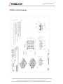
14.1 MCU-30 RUGGED DRAWINGS ....................................................................... 41
14.2 MCU-30 LITE DRAWINGS .............................................................................. 42
15 APPENDIX C – CONNECTORS’ PINOUT .................................................... 43
15.1 MAIN (DATA) CABLE .................................................................................... 43
15.2 POWER CABLE ............................................................................................. 44
15.3 LITE SYSTEM DATA CONNECTOR .................................................................... 45
15.4 LITE SYSTEM POWER CONNECTOR ................................................................. 46
16 APPENDIX D –TROUBLESHOOTING .......................................................... 47

MCU-30 User Manual
Page : 6 / 51
This page contains information which is protected by copyright and is proprietary to Mobilicom Ltd.
No part of this document may be used, copied, disclosed or conveyed to another party without prior written consent of Mobilicom Ltd
List of Figures
Figure 1: MCU-30 .................................................................................................................12
Figure 2: Asymmetric link configuration ................................................................................13
Figure 3: MCU-30 Front View ...............................................................................................15
Figure 4: MCU-30 Lite Front View ........................................................................................15
Figure 5: MCU-30 Rear View................................................................................................17
Figure 6: MCU-30 Lite Rear View .........................................................................................18
Figure 7: shows the transmit frames of VC and Node from Power Up ..................................23
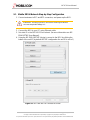
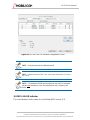
Figure 8: MC-EMA-PTP connect to screen ...........................................................................24
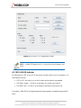
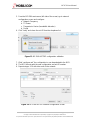
Figure 9: MC-EMA-PTP Configuration screen ......................................................................25
Figure 10: Transmit frames of MCUs in Mobile MESH from Power Up .................................27
Figure 11: Simple air transmission vector .............................................................................27
Figure 12: MC-EMA-MPTMP connect to screen ...................................................................28
Figure 13: MC-EMA-MPTMP configuration validation ...........................................................29
Figure 14: MC-EMA-MPTMP Network configuration screen .................................................29
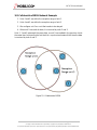
Figure 15: Collaborative MESH ............................................................................................32
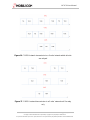
Figure 16: C.MESH network transmission in a 3 units’ network which all units are relayed ..33
Figure 17: C.MESH network transmission in a 3 units’ network unit 2 is relay only ...............33
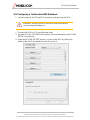
Figure 18: MC-EMA-MPTMP connect to screen ...................................................................35
Figure 19: MC-EMA-MPTMP configuration validation ...........................................................35
Figure 20: MC-EMA-MPTMP network configuration screen ..................................................36
Figure 21: MAIN Connector Front View (MCU-30 side) ........................................................43
Figure 22: PWR Connector Front View (MCU-30 side) .........................................................44
Figure 23: Lite System Data Connector (MCU-30 side) ........................................................45
Figure 24: Lite System Power Connector (MCU-30 side) .....................................................46

MCU-30 User Manual
Page : 7 / 51
This page contains information which is protected by copyright and is proprietary to Mobilicom Ltd.
No part of this document may be used, copied, disclosed or conveyed to another party without prior written consent of Mobilicom Ltd
List of Tables
Table 1: Abbreviation List ......................................................................................... 11
Table 2: MCU-30 Mechanical Specifications ............................................................ 19
Table 3: MCU-30 Power Specifications .................................................................... 21
Table 4: MCU-30 Environmental Specifications ....................................................... 21
Table 5: Embedded GPS Characteristics of the MCU-30 ......................................... 22
Table 6: MAIN Connector Type and Pin Mapping (connectors on cable side) ......... 43
Table 7: PWR Connector Type and Pin Mapping ..................................................... 44
Table 8: Lite System Data Connector Pin Mapping .................................................. 45
Table 9: Lite System Power Connector Pin Mapping ............................................... 46

MCU-30 User Manual
Page : 8 / 51
This page contains information which is protected by copyright and is proprietary to Mobilicom Ltd.
No part of this document may be used, copied, disclosed or conveyed to another party without prior written consent of Mobilicom Ltd
1 Quick Start Guide
If you are familiar with Mobilicom's MCUs, use this guide to prepare for operation. If
you are not familiar with the Mobilicom MCUs, it is recommended to read the entire
user guide. You can also visit the Mobilicom website for more material and videos at
http://www.mobilicom.com
Before turning the MCU on:
1. Connect antennas to the MCU RF1 and RF2 connectors.
2. Connect the GPS antenna to the AUX connector (For a Mobile MESH and
Collaborative MESH links it is mandatory to connect the GPS antenna).
3. Connect the data cable to the MAIN connector.
4. Connect the power cable.
5. Connect a DC power source to the power cable according to the specification.
6. If the MCUs are pre-configured, they will start operating automatically (plug and
play).
5. Otherwise: connect an Ethernet cable between the data cable and the PC’s
Ethernet adapter.
7. Use the MC-EMA to configure the unit.
CAUTION – Powering up an MCU unit without connecting the antennas
can cause unrepairable damage to the MCU-30.

MCU-30 User Manual
Page : 9 / 51
This page contains information which is protected by copyright and is proprietary to Mobilicom Ltd.
No part of this document may be used, copied, disclosed or conveyed to another party without prior written consent of Mobilicom Ltd
2 Introduction
As a leading global mission-critical-communications solution provider, Mobilicom
develops and delivers Bound-Free Mobile Private Network® technology and
solutions for wireless mobile networks, without the need for any infrastructure. By
leveraging 4G technology combined with Mobile MESH network topology,
Mobilicom assures optimal secured wireless communications.
All our products and solutions are designed to operate as a unified entity on a
single platform, regardless of which unit is operating. With versatile network
topologies and large product portfolio, Mobilicom caters to every deployment and
project scope from small to large scale with the highest flexibility, reliability and
mobility in the market.
2.1 Abbreviation List
BPS
Bits Per Second
BW
Bandwidth
CEP
Circular Error Probable (Accuracy)
CINR
Carrier to Interference and Noise Ratio (Signal to Noise Ratio)
CPLD
Complex programmable logic device
CRC
Cyclic Redundancy Code
dB
Decibel
dBm
Power ratio in decibels of the measured power referenced to
one milliwatt
CDD
Cyclic Delay Diversity
CTC
Convolutional Turbo Code
DC
Direct Current
EMA
Element Management Application
EMI
Electromagnetic Interference
ETH
Ethernet
ETSI
European Telecommunication Standard Institute
FAE
Field Application Engineer
FCC
Federal Communication Commission
FEC
Forward Error Correction
FFT
Fast Fourier Transform

MCU-30 User Manual
Page : 10 / 51
This page contains information which is protected by copyright and is proprietary to Mobilicom Ltd.
No part of this document may be used, copied, disclosed or conveyed to another party without prior written consent of Mobilicom Ltd
Freq.
Frequency
FW
Firmware
GHz
Gigahertz
GPS
Global Positioning System
HD
High Definition (Video)
HPA
High Power Amplifier
HW
Hardware
ID
Identification (Number)
IP
Internet Protocol
LAN
Local Area Network
LAT
Latitude
LED
Light Emitting Diode
LON
Longitude
LOS
Line Of Sight
mW
Milli Watt
MBR
Multi Band Radio
MCU
Mobilicom Communications Unit
MHz
Mega Hertz
MIMO
Multiple In Multiple Out
MRC
Maximal Ratio Combining
MPTMP
Multi-Point To Multi-Point
Node
Mobilicom Communications Unit, In PTP setup act as end point
communication unit
N.C
Not Connected
OEM
Original Equipment Manufacturer
OFDM
Orthogonal Frequency Division Modulation
OS
Operating System
PC
Personal Computer
PPS
Pulse Per Second
PTP
Point To Point
QAM
Quadrature Amplitude Modulation
QPSK
Quadrature Phase Shift Keying (modulation)
RF
Radio Frequency

MCU-30 User Manual
Page : 11 / 51
This page contains information which is protected by copyright and is proprietary to Mobilicom Ltd.
No part of this document may be used, copied, disclosed or conveyed to another party without prior written consent of Mobilicom Ltd
RMS
Root Mean Square (Average)
RSSI
Receiver Signal Strength Indication
RX
Receive
SBAS
Satellite Based Augmentation System
SW
Software
TDD
Time Division Duplexing
TDMA
Time Division Multiple Access
TX
Transmit
UAV
Unmanned Aerial Vehicle
UGV
Unmanned Ground Vehicle
VC
Virtual Concentrator, Mobilicom Communications Unit in PTP setup
act as end point communications unit that distribute clocks in the
system
VLAN
Virtual LAN
VPN
Virtual Private Network
Table 1: Abbreviation List

MCU-30 User Manual
Page : 12 / 51
This page contains information which is protected by copyright and is proprietary to Mobilicom Ltd.
No part of this document may be used, copied, disclosed or conveyed to another party without prior written consent of Mobilicom Ltd
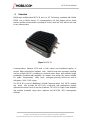
3 Overview
Mobilicom's multifunctional MCU-30 unit is a 4G Technology combined with Mobile
MESH (not a cellular device), IP communications unit that delivers ad-hoc direct
wireless mobile communication including HD Video, data and VoIP without the need
for any infrastructure.
Figure 1: MCU-30
Communications between MCU units is both robust and broadband quality, of
several Mbps transmission between units. Ideal for large area coverage, including
non-line-of-sight (N-LOS), conditions in rural and urban areas, with extended range
provided by a powerful relay capability. Its compact size makes this device suitable
for public transportation, utility grids, emergency/security vehicles as well as
helicopters / UAV / UGV usage.
The MCU-30 is part of Mobilicom’s Mobile Communications Unit (MCU) product
line which also includes the MCU-200, a high-end, high performance product
optimized for various land, air and sea platforms. MC-HPA, is a High-Power Amplifier
that enables extended range when required and MC-EMA, MCU management
software.

MCU-30 User Manual
Page : 13 / 51
This page contains information which is protected by copyright and is proprietary to Mobilicom Ltd.
No part of this document may be used, copied, disclosed or conveyed to another party without prior written consent of Mobilicom Ltd
3.1 Network Topologies and Applications
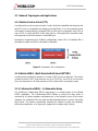
3.1.1 Mobile Point-to-Point (PTP)
A mobile point-to-point system includes 2 units, while the bandwidth ratio between the
two MCU units is configurable according to the application. It can be symmetric when
a full duplex communication is required (50% to each unit) or asymmetric up to 10% to
one unit (VC or node) and 90% to the other unit (i.e. Helicopter which transmits video
to the ground unit and its camera is controlled by it).
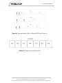
Example for asymmetric link: 8.4Mb/s configuration, where 10% of available BW is
allocated for uplink and 90% is allocated for downlink
Figure 2: Asymmetric link configuration
3.1.2 Mobile MESH - Multi-Point-to-Multi-Point (MPTMP)
A multi-point-to-multi-point network is a cluster of MCUs over a radio link. The cluster
includes at least 2 MCU units and can run up to 32 MCUs. Each MCU unit receives
from, and transmits to, all other members of the cluster within a reception range.
3.1.3 Collaborative MESH – Collaborative Relay
The Mobilicom Collaborative MESH technology is an enhancement to the Mobile
MESH capabilities. The Collaborative MESH allows to choose the data, which is
received by all cluster members simultaneously, to be relayed by any of the cluster
members (i.e. multiple MCUs can relay the data transmitted from a specific unit at the
same time). This feature significantly extends the network's range and reliability,
without any implication on its capacity (compared to a simple relay system).

MCU-30 User Manual
Page : 14 / 51
This page contains information which is protected by copyright and is proprietary to Mobilicom Ltd.
No part of this document may be used, copied, disclosed or conveyed to another party without prior written consent of Mobilicom Ltd
3.2 MCU-30 Main Features
•
• Diversity support MIMO antenna processing technologies.
• Scalable solution from a Mobile Point-to-Point to a MPTMP MESH
• High mobility with continuous transmissions up to 800km/h
• Mobile broadband network
• Small physical dimensions (portable device)
• Low power consumption (less than 10W)
• Plug-and-play installation
• Battery operated
• Dual power feed for hot swap during operation
3.3 Packets supported by the Mobilicom network
The MCU physical link supports Ethernet (IEEE 802.3) which includes:
1. Ethernet, VLAN Services, VPN and any other Protocol over IP.
2. Including real time applications using RT Protocols such as: Voice, Video, Data
3. Broadcast, Multicast, Unicast
Any Ethernet packet received by the MCU’s Ethernet port, is encapsulated with
Mobilicom’s standard frame for transmitting over the air-link to the remote MCU. The
remote MCU recovers the original Ethernet packet and forwards it to the Ethernet port.
NOTE – The MCU is similar to Ethernet layer 1 (physical layer) which makes
the integration with your equipment to be nothing more than connecting the ETH
cable.

MCU-30 User Manual
Page : 15 / 51
This page contains information which is protected by copyright and is proprietary to Mobilicom Ltd.
No part of this document may be used, copied, disclosed or conveyed to another party without prior written consent of Mobilicom Ltd
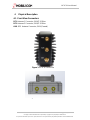
4 Physical Description
4.1 Front View Connectors
RF1: Antenna 1 Connector, SMA/F 50 Ohm
RF2: Antenna 2 Connector, SMA/F 50 Ohm
AUX: GPS Antenna Connector, SMA (Female)
Figure 3: MCU-30 Front View
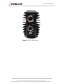
Figure 4: MCU-30 Lite Front View

MCU-30 User Manual
Page : 16 / 51
This page contains information which is protected by copyright and is proprietary to Mobilicom Ltd.
No part of this document may be used, copied, disclosed or conveyed to another party without prior written consent of Mobilicom Ltd
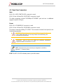
4.2 Rear View Connectors
Main:
MCU-30: A HR22-12WTRA-20P connector is used.
MCU-30 Lite: A Molex P/N: 5015715007 connector is used.
The data connectors include 10/100Mbps ETHERNET port and can in additional
support Serial RS-232 port.
Power:
MCU-30: A LF10WBRB-4P connector is used.
MCU-30 Lite: A Molex P/N: 5023520600 connector is used.
The power connecters utilizing 7-14.5VDC. The connector includes Dual Inputs for Hot
Swap during operation.
CAUTION – Connecting two batteries in parallel for a long period might
cause common discharge. For hot swap connect the second battery and
disconnect the first one after.
CAUTION – When an MCU-30 is carried by a personnel, environment
temperature should not exceed 45°C (113°F)
NOTE –Information about the connectors pin assignment is available in
Appendix C – Connectors Pinout
LED: The MCU-30 LED indicates power up and link status

MCU-30 User Manual
Page : 17 / 51
This page contains information which is protected by copyright and is proprietary to Mobilicom Ltd.
No part of this document may be used, copied, disclosed or conveyed to another party without prior written consent of Mobilicom Ltd
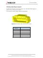
Figure 5: MCU-30 Rear View

MCU-30 User Manual
Page : 18 / 51
This page contains information which is protected by copyright and is proprietary to Mobilicom Ltd.
No part of this document may be used, copied, disclosed or conveyed to another party without prior written consent of Mobilicom Ltd
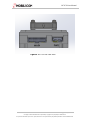
Figure 6: MCU-30 Lite Rear View

MCU-30 User Manual
Page : 19 / 51
This page contains information which is protected by copyright and is proprietary to Mobilicom Ltd.
No part of this document may be used, copied, disclosed or conveyed to another party without prior written consent of Mobilicom Ltd
5 Mechanical Specifications
The MCU-30 has various packaging options enabling a wide range of applications and
installation scenarios.
The most common packaging option is the outdoor unit with rugged casing, designed
for harsh environment conditions and flight ready.
An extended ruggedized environmental casing should be used for extreme
environmental conditions and is available for ordering.
There is an option for an Lite package (electronic boards only) which does not include
any casing. It is commonly used for embedding the unit as OEM into systems such as
UAVs, robots and other applications. In such cases, the customer/partner is
responsible for the mechanical casing and mechanical design considerations such as
cooling, (heat sink), sealing etc.
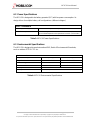
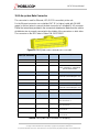
The following table shows the MCU-30 mechanical details for various packages
types.
Dimensions
[HxWxD] cm
[HxWxD] inch
Weight (g)
Weight (Oz)
Lite Package
7.4 x 8.0 x 2.7 cm
2.9 x 3.15 x 1.1”
140 gr.
4.94 oz.
Ruggedized
12 x 9 x 6 cm
4.7 x 3.5 x 2.3”
550 gr.
19.5 oz.
Extended Rugged
12 x 9 x 6 cm
4.7 x 3.5 x 2.3”
550 gr.
19.5 oz.
Table 2: MCU-30 Mechanical Specifications
6 Technical Specifications
6.1 Radio and Modem Specifications
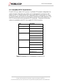
6.1.1 Frequency bands available with the MCU-30:
• 700-950MHz
• 2.3-2.7GHz
• 2.4GHz unlicensed band
• 4.9-5.9GHz (including all the unlicensed bands).
Additionally, there is an option for a multiband radio including 2 different bands within
the same MCU unit. The MCU-30 family is hardware ready to support any frequency
between 70MHz and 6GHz upon specific demand submitted by the customer.
6.1.2 Antennas
Various standard antennas Dipole, 2dBi maximum gain, Omni with SMA/M connector
can be supported.

MCU-30 User Manual
Page : 20 / 51
This page contains information which is protected by copyright and is proprietary to Mobilicom Ltd.
No part of this document may be used, copied, disclosed or conveyed to another party without prior written consent of Mobilicom Ltd
6.1.3 RF Characteristics
• Max output power: 2 x 0.5W per channel
• Average output power :2x 200mW per channel (23dBm)
• Noise Figure: 5dBm
• Transmission Power Control Range: 50dB in 1dB steps.
• Radio Access Method: OFDM - TDMA
• Configuration & Diversity Support: 2X2 MIMO with MRC(RX) and CDD(TX)
• Frequency Resolution: 0.25MHz
• Channel bandwidth: Configurable 4.2/8.4MHz
• FFT Supported: 512
• Guard band: 64 sub-carries each side
• Total subcarriers used per symbol: 384
• Data carriers used: 336
• Pilot carriers used: 48
• Sub carrier spacing: 13KHz for 5MHz bandwidth with 5msec frame
• Modulations: QPSK
• FEC methods: CTC
• FEC Ratios ¾ , ½ , ¼
• Error Detection: CRC32
• Full TDD asymmetrical duplexing
Flexible ratio from 1:1 to 1:9 in Mobile PTP
Resolution of 1% between all units in Mobile MESH and Collaborative MESH
networks
NOTE – The wide configurable power control range enables transmitting in low
TX power when not needed and by that reducing the power consumption.
Page is loading ...
Page is loading ...
Page is loading ...
Page is loading ...
Page is loading ...
Page is loading ...
Page is loading ...
Page is loading ...
Page is loading ...
Page is loading ...
Page is loading ...
Page is loading ...
Page is loading ...
Page is loading ...
Page is loading ...
Page is loading ...
Page is loading ...
Page is loading ...
Page is loading ...
Page is loading ...
Page is loading ...
Page is loading ...
Page is loading ...
Page is loading ...
Page is loading ...
Page is loading ...
Page is loading ...
Page is loading ...
Page is loading ...
Page is loading ...
Page is loading ...
-
 1
1
-
 2
2
-
 3
3
-
 4
4
-
 5
5
-
 6
6
-
 7
7
-
 8
8
-
 9
9
-
 10
10
-
 11
11
-
 12
12
-
 13
13
-
 14
14
-
 15
15
-
 16
16
-
 17
17
-
 18
18
-
 19
19
-
 20
20
-
 21
21
-
 22
22
-
 23
23
-
 24
24
-
 25
25
-
 26
26
-
 27
27
-
 28
28
-
 29
29
-
 30
30
-
 31
31
-
 32
32
-
 33
33
-
 34
34
-
 35
35
-
 36
36
-
 37
37
-
 38
38
-
 39
39
-
 40
40
-
 41
41
-
 42
42
-
 43
43
-
 44
44
-
 45
45
-
 46
46
-
 47
47
-
 48
48
-
 49
49
-
 50
50
-
 51
51


Ask a question and I''ll find the answer in the document
Finding information in a document is now easier with AI
Other documents
-
Renesas M3S-UFLA32R User manual
-
-
Wireless Solution T-1 Specification
-
Microchip Technology LORA User manual
-
Analog Devices Blackfin Getting Started
-
Poly RealPresence Web Suite Administrator Guide
-
-
-
-
Texas Instruments Secure In-Field Firmware Updates for MSP MCUs Application Note