Digital View ACM-1024 Owner's manual
- Category
- TVs & monitors
- Type
- Owner's manual

ANALOG INTERFACE CONTROLLER
FOR XGA RESOLUTION TFT LCD
Model: ACM-1024
(Part number: 4164600-3X)
INSTRUCTIONS
CONTENTS
Page: 2.Introduction
2. System design – Diagram of a suggested system
3. Assembly notes – Important information about system elements
4.Connection & Operation – How to use the controller
7. Connectors, pinouts & jumpers – Essential connection information
12. Controller dimensions
13. Application notes
14. Troubleshooting
15. Specifications
16. Warranty, Caution & Limitation of Liability
16. Contact details
It is essential that the sections on Assembly Notes and Connectors, Pinouts &
Jumpers is read and understood before connecting or powering up this controller.

Page 2
INTRODUCTION
Designed for LCD monitor and other flat panel display applications, the ACM-1024 controller provides an auto-input
synchronization and easy to use interface controller for:
Ø TFT (active matrix) LCDs of 1024x768 resolution;
Ø Computer video signals of VGA, SVGA and XGA standard;
Ø Good image expansion quality.
HOW TO PROCEED
ØEnsure you have all parts and that they are correct, refer to:
wConnection diagram (separate document for each panel)
wConnector reference (in following section)
wAssembly notes
ØCheck controller switch and jumper settings (errors may damage the panel)
ØPrepare the PC
ØConnect the parts
ØUnderstand the operation and functions ( in following section)
IMPORTANT USAGE NOTE
This product is for use by system developers and integrators, the manufacturer accepts no liability for damage or injury
caused by the use of this product. It is the responsibility of the developer, integrators or other user of this product to:
ØEnsure that all necessary and appropriate safety measures are taken.
ØObtain suitable regulatory approvals as may be required.
ØCheck power settings to all component parts before connection.
ØUnderstand the operation and connectivity requirements of this controller.
DISCLAIMER
There is no implied or expressed warranty regarding this material.
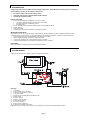
SYSTEM DESIGN
A typical LCD based display system is likely to comprise the following:
Summary:
1. LCD panel
2. LCD controller card, ACM-1024
3. LCD connector board (if necessary)
4. LCD signal cables
5. Inverter for CCFT backlight (if not built into LCD)
6. Inverter cable
7. Function controls
8. Function controls cable
9. Status LED & cable kit
10. PC VGA (analog) in
11. Power supply (+12VDC in)
12. Enclosure or mounting (not shown)
Digital View offers a range of accessories such as listed above, to make up complete display solution.
10
2

Page 3
ASSEMBLY NOTES
This controller is designed for monitor and custom display projects using 1024x768 resolution TFT panels with a VGA, SVGA
or XGA signal input. The following provides some guidelines for installation and preparation of finished display solution.
ØØ Preparation: Before proceeding it is important to familiarize yourself with the parts making up a system and the various
connectors, mounting holes and general layout of the controller. As much as possible connectors have been labeled.
Guides to connectors and mounting holes are shown in the following relevant sections.
ØØ 1. LCD Panel: This controller is designed for typical TFT panels with 5V or 3.3V TTL or LVDS interface. For LVDS
interface panel a separate add-on board is required. Due to the variation between manufacturers of signal timing and
other panel characteristics factory setup and confirmation should be obtained before connecting to a panel. (NOTE:
Check panel power jumper settings before connection)
NOTE: This controller supports up to 8-bit per colour, for panels of lower bits (eg 3 x 3 bit, 3 x 4 bit etc), connection of the
panel signal high value should correspond to the controllers highest bit. For example for a 3 x 3 bit panel R2 on the panel
should connect to R7 on the controller, in this case R0~4 on the controller will not be connected. For a 3 x 6 bit panel R5
on the panel should be connected to R7 on the controller. For a 3 x 8 bit panel R7 on the panel should be connected to
R7 on the controller. Same for G & B.
ØØ 2. Controller card: Handle the controller card with care as static charge may damage electronic components.
ØØ 3. LCD connector board: Different makes and models of LCD panel require different panel signal connectors and
different pin assignments. The connector board may not necessary for some Digital View cables that direct plug to the
LCD panel.
ØØ 4. LCD signal cable: In order to provide a clean signal it is recommended that LCD signal cables are no longer than
33cm (13 inches). If loose wire cabling is utilized these can be made into a harness with cable ties. Care should be
taken when placing the cables to avoid signal interference. Additionally it may be necessary in some systems to add
ferrite cores to the cables to minimize signal noise.
ØØ 5. Inverter: This will be required for the backlight of an LCD, some LCD panels have an inverter built in. As panels may
have 1 or more backlight tubes and the power requirements for different panel models backlights may vary it is important
to match the inverter in order to obtain optimum performance. See Application notes for more information on connection.
ØØ 6. Inverter Cables: Different inverter models require different cables and different pin assignment. Make sure correct
cable pin out to match the inverter. Using wrong cable pin out may damage the inverter.
ØØ 7. Function Controls: The following section ‘Operation’ discusses the controls required and the section ‘Connectors,
jumpers & pinouts’ provides the detail. The controls are minimal for ease of use: On/Off, Brightness (depends on
inverter), OSD (5 momentary buttons).
ØØ 8. Function controls cable: The cables to the function switches should be of suitable quality and length so that
impedance does not affect performance. Generally lengths up to 1 metre (3 feet) should be acceptable.
ØØ 9. Status LED: The pin direction of the LED should be corrected for right colour indication. Red colour stands for
standby. Green colour stands for signal on. It is an optional part only, can be unconnected.
ØØ 10. Analog VGA Input Cable: As this may affect regulatory emission test results and the quality of the signal to the
controller, a suitably shielded cable should be utilized.
ØØ Power Input: 12V DC is required, this should be a regulated supply. Although the controller provides power regulation for
the LCD power this does not relate to the power supplied to the backlight inverter. If an unregulated power supply is
provided to an inverter any fluctuations in power may affect operation, performance and lifetime of the inverter and or
backlight tubes.
ØØ Power Output: An auxiliary power output is available providing 5V and 12V DC power, this can be used for accessories
such as touch panels. Note the controller has an overall 3Amp current limit and the current available from the auxiliary
power output will be dependent on the power input and other system requirements.
ØØ Power Safety: Note that although only 12VDC is supplied as ‘power-in’ a backlight inverter for panel backlighting
produces significantly higher voltages (the inverter does not connect to the ground plane). We strongly advise
appropriate insulation for all circuitry.
ØØ EMI: Shielding will be required for passing certain regulatory emissions tests. Also the choice of external Controller to PC
signal cable and power supply can affect the result.
ØØ Ground: The various PCB mounting holes are connected to the ground plane.
ØØ Servicing: The controller is not user serviceable or repairable. Warranty does not cover user error in connecting up to
the controller and is invalidated by unauthorized modification or repairs.
ØØ Controller Mounting: It is recommended that a clearance of at least 10mm is provided above and 5mm below the
controller when mounted. Additionally consideration should be given to:
w Electrical insulation
w Grounding.
wEMI shielding.
wCable management. Note: It is important to keep panel signal cables apart from the inverter & backlight cables to
prevent signal interface.

Page 4
wHeat & ventilation: Heat generated from other sources, for example the backlight of a very high brightness panel may
generate significant heat which could adversely affect the controller.
wOther issues that may affect safety or performance.
ØØ Touch Panels: Support for touch panels or other low power consumption accessories is available by:
ww Connector CNA1 provides 5V & 12V DC which can be used to power such accessories subject to a maximum
loading recommended at 500mA.
ØØ PC Graphics Output: A few guidelines:
wSignal quality is very important, if there is noise or instability in the PC graphics output this may result in visible noise
on the display.
wVertical refresh rate should be set to 60Hz preferable.
wNon-interlaced is required.
IMPORTANT: Please read the Application Notes section for more information.
CONNECTION & OPERATION
CAUTION: Never connect or disconnect parts of the display system when the systrem is powered up as this may cause
serious damage.
CONNECTION
Connection and usage is quite straight forward (it is useful to have the relevant connection diagram available at this time):
1. LCD panel & Inverter: Connect the inverter (if it is not built-in the panel) to the CCFT lead connector of the LCD
panel.
2. TTL type panels: Plug the signal cables direct to CN2, CN3 and CN4 (necessary for 8-bit panel only) on the
controller board. Plug the other end of cables to the LCD connector board (if connector board is required, otherwise
the signal can be direct plug to the LCD panel connector). Then plug the board connector to the LCD panel
connector.
LVDS/PanelLink type panels: A LVDS/PanelLink transmitter board is required. Plug the transmitter board to CN2,
CN3 and CN4 (necessary for 8-bit panel only). Then insert the LCD signal cable with controller end to the connector
on the transmitter board. Insert the panel end of the cable the LCD panel connector.
3. Inverter & Controller: Plug the inverter cable to CNB1 and CNA1 (if necessary). Plug another end to the connector
on the inverter.
4. Function switch & Controller: Plug the OSD switch mount cable to CNC1 on the controller board and another to
the OSD switch mount.
5. LED & Controller: Plug in a 3-way with dual colour LED to connector LED1 on the controller board.
6. Jumpers & Switches: Check all jumpers and switches (SW1) are set correctly. Details referring the connection
diagram (a separate document) or the jumpers and switches setting table (in the following section).
7. Jumpers & Inverter & Panel voltage: Particularly pay attention to the settings of JA3, JB2, JB3, JP6. JB2 & JB3
are used for inverter control (read inverter specification and information on the jumper table to define the correct
settings). JA3 & JP6 are used for panel voltage input (read panel specification and information on the jumper table
to define the correct settings).
8. VGA cable & Controller: Plug the VGA cable to the connector P1 on the controller board.
9. Power supply & Controller: Plug the DC 12V power in to the connector PP1.
10. Power on: Switch on the controller board and panel by using the OSD switch mount.
The red LED will light up when power on. The LED will change to green when VGA signal on.
General:
ØIf you are using supplied cables & connectors, ensure they are correct for the model of panel and controller.
ØIf you are making your own cables & connectors refer carefully to both the panel & inverter specifications and the section
in this manual, “Connector, Pinouts & Jumpers” to ensure the correct pin to pin wiring.
PC SETTINGS
The controller has been designed to take a very wide range of input signals however to optimize the PC’s graphics
performance we recommend choosing 60Hz vertical refresh rate – this will not cause screen flicker.
OPERATION
Once the system has been connected and switched on there are a number of functions available to adjust the display
image as summarized in the following sections. The settings chosen will be saved for each mode independently.

Page 5
LCD DISPLAY SYSTEM SETTINGS
NOTE: By way of explanation the following refers to a set of sample buttons that may be obtained as an option. In
addition to power on/off and connection for backlight brightness the controller provides an On Screen Display of certain
functions which are controlled by 5 momentary type buttons (analog VR type) or 8 momentary type buttons (digital type):
Controls Analog VR type Digital type
On/Off – turns controller board power on VR toggle switch On/Off button
Brightness – controls backlight brightness Rotary VR Brightness +/- buttons
Menu – turns OSD menu On or Off (it will auto time
off) Menu button Menu button
Select down – moves the selector to the next
function (down) SEL DN SEL DN
Select up – moves the selector to the previous
function (up) SEL UP SEL UP
+ – increase the setting/confirm the select + +
- – decrease the setting - -
MANUAL & REMOTE CONTROL
The following table shows the comparison of functions available from different controls:
Operation One for All Sony multi remote DV switchmount DV digital VR
switchmount
Menu Power Power Menu Menu
Default Mute Mute - -
Select + Ch+ Ch+ Select + Select +
Select - Ch- Ch- Select - Select -
Setting + Vol+ Vol+ Setting + Setting +
Setting - Vol- Vol- Setting - Setting -
Other multi-system IR transmitters will also be suitable if they support common Sony signal timings.
OSD Functions
Auto Setup Auto setting the display, e.g. positions, image size, tuning, etc.
Press + to activate auto setup.
Brightness Increase/decrease panel brightness level.
Press – or + (- + nn), range: 0 to 100
Contrast Increase/decrease panel brightness level.
Press – or + (- + nn), range: 0 to 100
Image Adjust 4Turns on the image adjust submenu
Languages 4Turns on the language submenu
OSD Settings 4Turns on the language submenu
Restore Factory Presets Loading factory default
Press – or + (Yes / No)
Information 4Turns on information submenu
Shows board information
Exit Turn off the OSD menu.
Press + turns off the OSD menu.
Items marked 4 have sub menus.
ON/Off/Brightness
SEL UP
SEL DN
+
-
Menu
Analog VR type
Digital type

Page 6
Image Adjust – submenu
Horizontal Position Move the image position horizontally
Press – or + (- + nn), range: 0 to 100
Vertical Position Move the image position vertically
Press – or + (- + nn), range: 0 to 100
Scale/Center 4Press + to turn on submenu
Sharpen 4Press + to turn on submenu
Color 4Press + to turn on submenu
Advanced 4Press + to turn on submenu
Exit Press + to go back to previous menu.
Languages – submenu
English Press + to activate English displayed OSD menu
French Press + to activate French displayed OSD menu
German Press + to activate German displayed OSD menu
Spanish Press + to activate Spanish displayed OSD menu
Chinese Press + to activate Chinese displayed OSD menu
OSD Settings – submenu
OSD Position 4Press + to turn on submenu
OSD Size 4Press + to turn on submenu
OSD Transparency Adjust the transparent level of the OSD menu
Press – or + (- + nn), range: 0 to 100, 4 steps
OSD Timeout Set menu time-out period
Press – or + (10 / 20 / 30 / 40 / 50 / 60 / 70 / 80 / 90 / 100 sec.)
Exit Press + to go back to previous menu.
Scale/Center – sub-submenu
Full Screen Full screen expansion
Maintain Aspect Ratio Expansion maintain aspect ratio
Center No expansion
Sharpen – sub-submenu
Smart Sharpening Select the best sharpness level among high, medium, low
High Select high sharpness level
Medium Select medium sharpness level
Low Select low sharpness level
Color – sub-submenu
Gamma correction 4Press + to turn on gamma correction submenu
Color Temp 4Press + to turn on color temperature submenu
RGB Adjust 4Press + to turn on RGB color adjustment submenu
Black Level Adjust 4Press + to turn on black level adjustment submenu
Save Color Settings Press & hold + for 3 seconds to save color settings
Restore Color Settings Press & hold + for 3 seconds to restore color settings
Restore Factory Colors Press & hold + for 3 seconds to restore factory settings
Exit Press + to go back to previous menu.
Advanced – sub-submenu
Phase Adjust Adjust data sampling position (tuning)
Press – or + (- + nn), range: 0 to 100
Clock Adjust Adjust the image size
Press – or + (- + nn), range: 0 to 100
Exit Press + to go back to previous menu.
OSD Position – sub-submenu
Horizontal Position Move OSD menu position horizontally
Press – or + (- + nn), range: 0 to 100
Vertical Position Move OSD menu position vertically
Press – or + (- + nn), range: 0 to 100
Exit Press + to go back to previous menu.
OSD Size – sub-submenu
Normal Normal OSD menu size
Double Double the OSD menu size
Gamma Correction – sub-sub-submenu
LCD Corrected Gamma corrected according to LCD characteristic
CRT Corrected Gamma corrected according to CRT characteristic
Color Temp – sub-sub-submenu
Cool Cool color temperature
Neutral Neutral color temperature
Warm Warm color temperature

Page 7
RGB Adjust – sub-sub-submenu
Red Adjust red color level
Press – or + (- + nn), range: 0 to 100
Green Adjust green color level
Press – or + (- + nn), range: 0 to 100
Blue Adjust blue color level
Press – or + (- + nn), range: 0 to 100
Exit Press + to go back to previous menu.
CONNECTORS, PINOUTS & JUMPERS
The various connectors are:
Summary: Connectors (18 bit = 3 x 6 bit)
Ref Purpose Description
CNA1 Auxiliary power JST 4-way, B4B-XH-A
CN2 Panel signal Hirose 28-pin, DF11-28DP-2DSA
CN3 Panel signal Hirose 32-pin, DF11-32DP-2DSA
CN4 Panel signal Hirose 20-pin, DF11-20DP-2DSA
CN5 Reserved for touch panel controller Hirose 10-pin, DF11-10DP-2DSA
CNB1 Backlight inverter JST 5-way, B5B-XH-A
CNB2 Alternate backlight inverter Hirose 10-pin, DF13-10P-1.25DSA
CNC1 Alternate function controls Hirose 9-pin, DF13-9P-1.25DSA
CNC2 Function controls JST 12-way, B12B-XH-A
JJ1 RS-232 serial control in Header pin 6x1
LED1 Dual color LED connector Header pin 3x1
P1 VGA analog input DB15-way DDC version (blue colour)
P2 VGA input (alternative) Header pin 8 x 2
PP1 DC power in DC power jack, 2.5mm contact pin diameter positive
PP2 DC power input (alternative) DC power Molex 2-pin 0.156” pitch

Page 8
Summary: Jumpers setting
Ref Purpose Note
JA1 On board +5V logic power enable 1-3 & 2-4 closed, factory set, do not remove
JA2 On board +3.3V logic supply enable 1-3 & 2-4 closed, factory set, do not remove
JA3 Panel power voltage select 1-3 & 2-4 = +5V panel voltage supply
3-5 & 4-6 = +3.3V panel voltage supply
JA4 RS-232 voltage level 1-3 & 2-4 = +12V
3-5 & 4-6 = +5V
JB1 PWM level select 1-2 = +5V
2-3 = +12V
CAUTION: Incorrect setting can damage inverter.
JB2 Backlight inverter on/off control – signal level 1-2 = On/Off control signal ‘High’ = +12V
2-3 = On/Off control signal ‘High’ = +5V
Open = On/Off control signal ‘High’ = Open collector
CAUTION: Incorrect setting can damage inverter.
JB3 Backlight inverter on/off control – polarity 1-2 = control signal ‘high’ = CCFT ON
2-3 = control signal ‘low’ = CCFT ON
JB4 Backlight brightness PWM – polarity 1-2 = high = ON
2-3 = low = ON
JB5 Backlight brightness signal. 1-2 = voltage
2-3 = PWM
JB6 Backlight brightness control 1-2 = VR (default)
2-3 = Voltage or PWM (selected by JB5)
JB7~8 Not present
JB9 Backlight inverter status 1-2 = active low
2-3 = active high
Open = status not known by MCU (default)
JB10 Backlight power control Short = by MCU
Open = always enable
JC1 Input power control Short = soft-power control
Open = switch mount control (default)
JP5 Coast signal to PLL Default open
JP6 +12V LCD power select for CN3 pin 3 Short = +12V DC enable
Open = NC (default)
JP7 Reserved Factory set to 1-2
JP8 Reserved Factory set to 1-2
JP9 Reserved Factory set to 2-3
JP11 Reserved Factory set to open
JP12 Panel selection 1-2 & 3-4 = double pixel panel
1-3 & 2-4 = single pixel panel
JP13 Noise scrambler selection Short = activate
Open = not activate (default)
SW1 Panel & function selection See table below
SW1: Panel and function selection
Pos. # Function Description
1Clock phase change Change to get best image quality
2Single/Double pixel panel support ON = Single-pixel panel
OFF = Double-pixel panel
3Reserved OFF
4Reserved OFF
PINOUTS
CNA1 - Auxiliary power output, JST B4B-XH-A
PIN SYMBOL DESCRIPTION
1AUX_12V +12V DC, 500mA max.
2AUX_GND Ground
3AUX_GND Ground
4AUX_Vcc +5V DC, 500mA max

Page 9
CN2 – Panel connector: HIROSE DF11-28DP-2DSA
PIN SYMBOL DESCRIPTION
1GND Ground
2GND Ground
3P_ER2 Even data bit R2
4P_OR2 Odd data bit R2
5P_ER3 Even data bit R3
6P_OR3 Odd data bit R3
7P_ER4 Even data bit R4
8P_OR4 Odd data bit R4
9P_ER5 Even data bit R5
10 P_OR5 Odd data bit R5
11 P_EG2 Even data bit G2
12 P_OG2 Odd data bit G2
13 P_EG3 Even data bit G3
14 P_OG3 Odd data bit G3
15 P_EG4 Even data bit G4
16 P_OG4 Odd data bit G4
17 P_EG5 Even data bit G5
18 P_OG5 Odd data bit G5
19 P_EB2 Even data bit B2
20 P_OB2 Odd data bit B2
21 P_EB3 Even data bit B3
22 P_OB3 Odd data bit B3
23 P_EB4 Even data bit B4
24 P_OB4 Odd data bit B4
25 P_EB5 Even data bit B5
26 P_OB5 Odd data bit B5
27 GND Ground
28 GND Ground
CN3 – Panel connector: HIROSE DF11-32DP-2DSA
PIN SYMBOL DESCRIPTION
1+12v DC +12v, reserved & not normally used
2+12v DC +12v, reserved & not normally used
3NC/VLCD12 No connection or 12V VLCD
4NC No connection
5GND Ground
6GND Ground
7P_ER6 Even data bit R6
8P_OR6 Odd data bit R6
9P_ER7 Even data bit R7 (MSB of lower colour bit panels)
10 P_OR7 Odd data bit R7 (MSB of lower colour bit panels)
11 P_EG6 Even data bit G6
12 P_OG6 Odd data bit G6
13 P_EG7 Even data bit G7 (MSB of lower colour bit panels)
14 P_OG7 Odd data bit G7 (MSB of lower colour bit panels)
15 P_EB6 Even data bit B6
16 P_OB6 Odd data bit B6
17 P_EB7 Even data bit B7 (MSB of lower colour bit panels)
18 P_OB7 Odd data bit B7 (MSB of lower colour bit panels)
19 GND Ground
20 GND Ground
21 Vcc DC +5v, reserved & not normally used
22 Vcc DC +5v, reserved & not normally used
23 VS Vertical sync
24 PwrDn Power down control signal (5v TTL)
25 P_HS Horizontal sync
26 P_DE Display enable
27 P_VLCD Panel supply (switched)
28 P_VLCD Panel supply (switched)
29 P_CLE Even dot clock (shift clock)
30 P_CKO Odd dot clock (shift clock)
31 GND Ground
32 GND Ground

Page 10
CN4 – Panel connector: HIROSE DF11-20DF-2DSA
PIN SYMBOL DESCRIPTION
1GND Ground
2GND Ground
3NC No connection
4NC No connection
5P_ER0 Even data bit R0
6P_OR0 Odd data bit R0
7P_ER1 Even data bit R1
8P_OR1 Odd data bit R1
9P_EG0 Even data bit G0
10 P_OG0 Odd data bit G0
11 P_EG1 Even data bit G1
12 P_OG1 Odd data bit G1
13 P_EB0 Even data bit B0
14 P_OB0 Odd data bit B0
15 P_EB1 Even data bit B1
16 P_OB1 Odd data bit B1
17 NC No connection
18 NC No connection
19 GND Ground
20 GND Ground
CN5 – Touch Panel connector: HIROSE DF11-10DF-2DSA
PIN SYMBOL DESCRIPTION
1GND Ground
2GND Ground
3Vcc Vcc to touch-panel controller board
4Vcc Vcc to touch-panel controller board
5NC No connection
6NC No connection
7GND Ground
8GND Ground
9+12V +12V to touch-panel controller board
10 +12V +12V to touch-panel controller board
CNB1 - To backlight inverter, JST B5B-XH-A
PIN SYMBOL DESCRIPTION
1GND Ground
2VBKL Backlight power supply, +12VDC (switched)
3BLCTRL Backlight On/Off control signal (refer to JB2 & JB3)
4BVR_WIP Backlight brightness VR pin WIP
5BVR_A Backlight brightness VR pin A
CNB2 – ALTERNATE BACKLIGHT INVERTER, HIROSE DF13-10P-1.25DSA
PIN SYMBOL DESCRIPTION
1+12V Backlight power supply, +12VDC (switched)
2+12V Backlight power supply, +12VDC (switched)
3Aux_Vcc Auxiliary power, +5VDC
4GND Ground
5GND Ground
6INV_STAT Inverter status
7BLCTRL Backlight On/Off control signal (refer to JB2 & JB3)
8BVR_B Backlight brightness VR pin B
9BVR_WIP Backlight brightness VR pin WIP, level or PWM
10 BVR_A Backlight brightness VR pin A
CNC1 - To control switches, JST B12B-XH-A
PIN SYMBOL DESCRIPTION
1PSWIN Power switch A
2SW_ON Power switch B
3BVR_A Backlight brightness VR pin A
4BVR_WIP Backlight brightness VR pin WIP
5BVR_B Backlight brightness VR pin B (470Ω resistor to +5V Vcc)
6GND Ground
7MENU OSD menu button
8-/LEFT OSD -/Left button
9+/RIGHT OSD +/Right button
10 SEL OSD Select down button
11 SEL_UP OSD Select up button
12 PWR Power button

Page 11
CNC2 - Alternate control switches, HIROSE DF13-9P-1.25DSA
PIN SYMBOL DESCRIPTION
1PWR Power button
2BL_UP Backlight brightness up
3BL_DN Backlight brightness down
4MENU OSD menu button
5SEL_UP OSD select up
6SEL_DN OSD select down
7PLUS/RIGHT OSD +/Right
8MINUS/LEFT OSD -/Left
9GND Ground
JJ1 – Serial control (RS-232), JST B6B-PH-K
PIN SYMBOL DESCRIPTION
1SDATA Reserved
2SCLK Reserved
3Vcc +5V
4TXD RS-232 Tx data
5GND Ground
6RXD RS-232 Rx data
P1 & P2 - ANALOG VGA INPUT - 15 way connector
PIN SYMBOL DESCRIPTION
1PCR Red, analog
2PCG Green, analog
3PCB Blue analog
4ID2 Reserved for monitor ID bit 2 (grounded)
5DGND Digital ground
6AGND Analog ground red
7AGND Analog ground green
8AGND Analog ground blue
9DDC_5V +5V power supply for DDC (optional)
10 DGND Digital ground
11 ID0 Reserved for monitor ID bit 0 (grounded)
12 DDC_SDA DDC serial data
13 HS_IN Horizontal sync or composite sync, input
14 VS_IN Vertical sync, input
15 DDC_SCL DDC serial clock
PP1 - 12VDC power supply - input
PIN DESCRIPTION
1+12VDC in middle pin
2Ground
PP2 – Alternate 12VDC power supply - input
PIN DESCRIPTION
1+12VDC
2Ground

Page 12
CONTROLLER DIMENSIONS
The maximum thickness of the controller is 20.6mm (measured from bottom of PCB to top of components, including
any underside components & leads). We recommend clearances of:
•5mm from bottom of PCB - if mounting on a metal plate we also recommend a layer of suitable insulation
material is added to the mounting plate surface.
•10mm above the components
•3~5mm around the edges
Any of the holes shown above can be used for mounting the PCB, they are 3.2mm in diameter. Other holes are used
for mounting inverters supplied as fitted options.
CAUTION: Ensure adequate insulation is provided for all areas of the PCB with special attention to high
voltage parts such as the inverter.

Page 13
APPLICATION NOTES
USING THE CONTROLLER WITHOUT SWITCHES ATTACHED
This is very straightforward:
ØWith controls attached and display system active make any settings for colour, tint and image position as required then
switch everything off.
ØRemove the control switches, the 12 way (CNC1) cables.
ØUse a jumper or similar to connect pins 1 & 2 on CNC1, this will fix the board On.
ØRefer to inverter specifications for details as to fixing brightness to a desired level, this may require a resistor, an open
circuit or closed circuit depending on inverter.
Summary: On CNC1 the only functions that are used are for On/Off and Brightness (if controller mounted inverter is used). On
CNC1 the pins are for momentary buttons so it doesn’t matter that no buttons are attached.
INVERTER CONNECTION
There are potentially 3 issues to consider with inverter connection:
1. Power
2. Enable
3. Brightness
Please read the following sections for a guide to these issues.
Inverter Power:As per the table for CNB1 pin 1 is ground and pin 2 provides 12V DC. This should be matched with the
inverter specification: see table.
CNC1
PIN DESCRIPTION
1ground
2+12VDC
Enable: This is a pin provided on some inverters for On/Off function and is used by this panel controller for VESA DPMS
compliance. If the inverter does not have an enable pin or the enable pin is not used then DPMS will not be
operational. Pin 3 should be matched to the inverters specification for the ‘enable’ or ‘disable’ pin.
CNC1
PIN DESCRIPTION
3enable
Further, jumpers JB2 & JB3 should be set to match the inverters specification for the enable pin power and High or Low
setting: see table.
Ref Purpose Note
JB2 inverter enable voltage 1-2 H=12V, 2-3 H=5V (Vcc), OPEN H=open collector
JB3 inverter control 1-2 H=On, 2-3 L=On
Brightness: There are various methods for brightness control and it is important to consider the specifications for the
inverter to be used. Generally the situation is:
1. Brightness can controlled by using a VR.
2. Brightness controlled adding a circuit such as PWM (Pulse Width Modulation).
3. No adjustment of brightness is possible.
CNC1 pins 4 & 5 are available for connecting to an inverter or circuit where VR control is supported.
CNC1
PIN DESCRIPTION
4VR WIP
5VR A
This can then be matched with function controls connected to CNC1 pins 3 & 4: see table.
CNC1
PIN DESCRIPTION
3VR A
4VR WIP

Page 14
TROUBLESHOOTING
General
A general guide to troubleshooting a flat panel display system it is worth considering the system as separate elements, such
as:
ØController (jumpers, PC settings)
ØPanel (controller, cabling, connection, PC settings)
ØBacklight (inverter, cabling, backlight tubes)
ØCabling
ØComputer system (display settings, operating system)
Through step by step cross checking with instruction manuals and a process of elimination to isolate the problem it is usually
possible to clearly identify the problem area.
No image:
ØIf the panel backlight is not working it may still be possible to just see some image on the display.
ØA lack of image is most likely to be caused by incorrect connection, lack of power, failure to provide a signal or incorrect
graphic card settings.
Image position:
ØIf it is impossible to position the image correctly, ie the image adjustment controls will not move the image far enough,
then test using another graphics card. This situation can occur with a custom graphics card that is not close to standard
timings or if something is in the graphics line that may be affecting the signal such as a signal splitter (please note that
normally a signal splitter will not have any bad effect).
Image appearance:
ØA faulty panel can have blank lines, failed sections, flickering or flashing display
ØIncorrect graphics card refresh rate, resolution or interlaced mode will probably cause the image to be the wrong size, to
scroll, flicker badly or possibly even no image.
ØIncorrect jumper settings on the controller may cause everything from total failure to incorrect image. CAUTION: Do not
set the panel power input incorrectly.
ØSparkling on the display: faulty panel signal cable.
Backlight:
Items to check include: Power input, Controls, Inverter and Tubes generally in this order. If half the screen is dimmer than the
other half:
ØCheck cabling for the inverter.
ØFor a specific backlight tube check the AC pins orientation (CAUTION: never reverse any DC power pins).
Also:
ØIf adjusting brightness control has no effect the chances are that the VR rating or method of adjusting brightness is not
compatible or correctly connected to the inverter.
ØIf system does not power down when there is a loss of signal.
Continued failure:
ØIf unit after unit keeps failing consider and investigate whether you are short circuiting the equipment or doing something
else seriously wrong.
Generally after common sense issues have been resolved we recommend step by step substitution of known working parts to
isolate the problem.

Page 15
SPECIFICATIONS
Panel compatibility 1024 x 768 TFT LCD’s from manufacturers such as
Sharp, NEC, Toshiba, IBM, Hitachi, Philips/Hosiden,
Fujitsu, Mitsubishi, Samsung, LG, Hyundai, etc though some factory
adjustment may be required for individual panel timings.
No. of colours Up to 3 x 8 bit providing 16.7 million colours.
Vertical refresh rate VGA, SVGA, XGA to VESA standards up to 85Hz
Dot clock (pixel clock) maximum 95MHz
Graphics formats Standard VGA, SVGA & XGA
Graphics mode auto detect Yes, VGA, SVGA & XGA
Standard input at source VGA analog (15-pin) standard, separate sync only
Controls available - On/Off
- Brightness (inverter)
- OSD menu,
- OSD select up
- OSD select down
- OSD setting +
- OSD setting -
Control interface - Buttons
- RS-232
Settings memory Settings are stored in non volatile memory
Multi-language OSD support 5 languages (English, French German, Spanish and Chinese)
VESA DPMS implementation Yes
Plug & Play VESA DDC 1, 2/b compatible
Voltage output for LCD +3.3V DC, +5V DC
Input voltage 12VDC
Power protection Fuse fitted - auto reset
DC Power handling An on board relay handles the power load for On/Off and power protection to
the LCD.
Power load maximum The controller has an overall 3Amp current limit.
Controller power consumption Approx 2.5W (controller logic only, no panel)
Controller dimensions 178mm x 91.5mm x 21mm
Storage temperature limits -40oC to +70oC
Operating temperature limits 0oC to +65oC
NOTES
Please note the following:
•For specific panel setup a sample of an LCD may be required (this will be returned) and a copy of the full technical
specifications for the panel from the manufacturer.
•Relayout and custom development services are available.
Graphics modes supported:
Ref Mode Resolution Hor. Freq
/ kHz
Vert.
Freq
/ Hz
Dot clock
/MHz
Remark
1Text 720 x 400 31.5 70 28.320
2Graphics 640 x 350 31.5 70 25.175
3Graphics 640 x 350 37.861 85 31.500
4Graphics 640 x 480 31.5 60 25.175
5Graphics 640 x 480 37.86 72 31.5
6Graphics 640 x 480 37.50 75 31.5
7Graphics 640 x 480 43.27 85 36
8Graphics 800 x 600 35.156 56 36
9Graphics 800 x 600 37.879 60 40
10 Graphics 800 x 600 48.08 72 50
11 Graphics 800 x 600 46.88 75 49.5
12 Graphics 800 x 600 53.67 85 56.25
13 Graphics 1024 x 768 48.36 60 65
14 Graphics 1024 x 768 56.48 70 75
15 Graphics 1024 x 768 57.52 72 75
16 Graphics 1024 x 768 60 75 78.75
17 Graphics 1024 x 768 68.68 85 94.5
The ACM-1024 may be able to scaling down (may not very good quality) the images that higher than XGA, e.g.
1152x864, 1280x960, 1280x1024, 1600x1200, etc, onto a XGA panel. The support of those modes are depending
on final testing.

Page 16
WARRANTY
The products are warranted against defects in workmanship and material for a period of one (1) year from the date of purchase
provided no modifications are made to it and it is operated under normal conditions and in compliance with the instruction
manual.
The warranty does not apply to:
•Product that has been installed incorrectly, this specifically includes but is not limited to cases where electrical short
circuit is caused.
•Product that has been altered or repaired except by the manufacturer (or with the manufacturer’s consent).
•Product that has subjected to misuse, accidents, abuse, negligence or unusual stress whether physical or electrical.
•Ordinary wear and tear.
Except for the above express warranties, the manufacturer disclaims all warranties on products furnished hereunder, including
all implied warranties of merchantability and fitness for a particular application or purpose. The stated express warranties are in
lieu of all obligations or liabilities on the part of the manufacturer for damages, including but not limited to special, indirect
consequential damages arising out of or in connection with the use of or performance of the products.
CAUTION
Whilst care has been taken to provide as much detail as possible for use of this product these instructions cannot be
relied upon as an exhaustive source of information. This product is for use by suitably qualified persons who
understand the nature of the work they are doing and are able to take suitable precautions and design and produce a
product that is safe and meets regulatory requirements.
LIMITATION OF LIABILITY
The manufacturer’s liability for damages to customer or others resulting from the use of any product supplied hereunder shall
in no event exceed the purchase price of said product.
TRADEMARKS
The following are trademarks of Digital View Ltd:
• Digital View
• ACM-1024
CONTACT DETAILS
Digital View has offices in Asia, Europe and USA also an internet site:
ASIADigital View Ltd
2201 Nanyang Plaza, 57 Hung To Road
Kwun Tong, Kowloon, Hong Kong
Tel: (852) 2861 3615 Fax: (852) 2520 2987
Sales: [email protected] Technical Support: [email protected]
EUROPE
Digital View Ltd
Millenium Studios, 5 Elstree Way
Borehamwood, Hertfordshire, WD6 1SF
England
Tel: (44) (0)181-236 1112 Fax: (44) (0)181-236 1116
Sales: [email protected] Support: [email protected]
USA Digital View Inc.
18440 Technology Drive, Building 130
Morgan Hill, California, 95037
USA
Tel: (1) 408-782 7773 Fax: (1) 408-782 7883
Sales: [email protected] Support: [email protected]
WEBSITE
www.digitalview.com
Specifications subject to change without notice
Revised: September 19, 1999 (AC-0800.doc) © Digital View Ltd 1999
-
 1
1
-
 2
2
-
 3
3
-
 4
4
-
 5
5
-
 6
6
-
 7
7
-
 8
8
-
 9
9
-
 10
10
-
 11
11
-
 12
12
-
 13
13
-
 14
14
-
 15
15
-
 16
16


Digital View ACM-1024 Owner's manual
- Category
- TVs & monitors
- Type
- Owner's manual
Ask a question and I''ll find the answer in the document
Finding information in a document is now easier with AI
Related papers
-
Digital View ACG-1024 Owner's manual
-
-
-
-
-
-
-
-
-