Kathrein 20510026 User manual

Category
TV signal amplifiers
Type
User manual

This manual is also suitable for

1 / 5
Zu dieser Anleitung
Dieses Dokument ist Teil des Produkts.
Das Gerät erst installieren und benutzen, nachdem Sie
dieses Dokument gelesen und verstanden haben.
Die in diesem Dokument beschriebenen Maßnahmen
immer in der angegebenen Reihenfolge durchführen.
Dieses Dokument während der Lebensdauer des
Geräts aufbewahren. Das Dokument an nachfolgende
Besitzer und Benutzer weitergeben.
Die aktuelle Version dieses Dokuments  nden Sie auf
www.kathrein.com.
Merkmale
Hohe Aussteuerfestigkeit der Verstärkerzüge
Hohe Entkopplung zwischen den Verstärkerzügen
Durch die Verwendung einer GaAs-Endstufe ist der
terrestrische Verstärker für BK-Anwendung geeignet
Schrittweise einstellbare Dämpfungssteller (1-dB-
Stufung) für den Sat- und den terrestrischen Bereich
(jeder Verstärkezweig wird getrennt eingestellt)
Schrittweise einstellbare Vorentzerrung (2/4/6 dB) im
Sat-Bereich (jeder SAT-Zweig wird getrennt eingestellt)
ermöglicht einen optimalen Schräglagenausgleich in
der Kaskade
Die Stromversorgung der Verstärkerzüge sowie des
LNBs erfolgt durch das eingebaute, hochef ziente
Schaltnetzteil
Durch Verwendung eines hochef zienten DC/DC-
Wandlers ist der Stromverbrauch des VWS2990
extrem gering
Geeignet für den Einsatz in Kathrein-Sat-ZF-Verteilsys-
temen mit 8 x Sat-ZF (zwei Satellitenpositionen)
Für die Innenmontage
Lieferumfang
VWS2900
Anleitung
Bestimmungsgemäßer Gebrauch
Der VWS2900 dient ausschließlich der Verstärkung von
Sat- und terrestrischen Signalen in Satellitenempfangsan-
lagen.
Jegliche anderweitige Nutzung oder die Nichtbeachtung
dieses Anwendungshinweises hat den Verlust der Gewähr-
leistung bzw. Garantie zur Folge.
VWS2900 20510026
Sat-ZF-Verteilsystem
Multischalter-Verteilnetzverstärker
Transport und Lagerung
Das Gerät in der Originalverpackung transportieren und
lagern.
Das Gerät im zulässigen Temperaturbereich von –25bis
+70 °C transportieren und von –5bis +45°C lagern.
Darauf achten, dass kein Kondenswasser gebildet wird.
geeignet für DVB-T/T2
2 / 5
Typ VWS2900
Bestellnummer 20510026
Eingänge 1 x terrestrisch 8 x Sat-ZF
Frequenzbereich MHz 47–862 950–2150
Verstärkung
1)
dB 17–21 22–24
Einstellbereich Dämpfungssteller (1-dB-Schritte) dB 0–15 0–15
Einstellbereich Entzerrung dB - 2/4/6
Max. Ausgangspegel (Störprodukte 3. Ordnung) dBµV 113
2)
115
3)
Max. Ausgangspegel (Störprodukte 2. Ordnung) dBµV 104
2)
110
3)
Max. Betriebspegel für BK (bis 862 MHz)
4)
dBµV 98 -
Entkopplung Stamm dB - 40
Eingangsnennspannung V 207 – 253 (50 – 60 Hz)
Spannung sekundär (Eingang horiz. low) V +18
Verfügbarer Fernspeisestrom (Eingang horiz. low) mA 500
Zulässige Umgebungstemperatur °C –20 bis +55
Schutzklasse/Schutzart (schutzisoliert) II (schutzisoliert) / IP 30
Anschlüsse F-Connectoren
Abmessungen (B x H x T) mm 285 x 148 x 43
Verpackungseinheit/Gewicht St./kg 1 (10)/1,1
1)
Frequenzabhängige Verstärkung (Preemphase) in Abhängigkeit der Schalterstellung für Vorentzerrung
2)
60-dB-IMA nach EN 60728-3
3)
35-dB-IMA nach EN 60728-3
4)
Nach EN 60728-3, 60-dB-CTB/CSO, CENELEC-Raster
Abmessungen in mm
Technische Daten
3 / 5
Montage- und Sicherheitshinweise
VORSICHT
Gefahr von Sachschäden am Gerät beim Betrieb in unsachgemäßen Umgebungsbedingungen!
Gerät nur in trockenen Innenräumen montieren.
Gerät nicht auf oder an leicht entzündlichen Materialien montieren.
Gerät mit einer Potenzialausgleichsleitung (Cu, mindestens 4mm
2
) versehen.
Die Sicherheitsbestimmungen der jeweils aktuellen Normen EN60728-11 und EN62368-1 beachten.
Nicht benutzte Anschlüsse abschließen (Einhalten der Störstrahlvorschrift).
Befestigungsmittel: Holzschrauben, max Ø: 4,0mm
Verbindungsstecker: HF-Stecker 75Ω (Serie F) nach EN61169-24.
Gerät installieren
Verstärker in eine Satellitenempfangsanlage einsetzen
Der Verstärker VWS 2900 wird am Eingang größerer Multischalterkaskaden oder als kaskadierbarer Verteilnetzverstärker
zum Ausgleichen von Kabel-, Abzweiger- oder Verteiler-Durchgangsdämpfungen in großen Verteilnetzen eingesetzt.
Sicherstellen, dass der Pegel am Eingang zwischen 50 bis max. 80 dBV liegt und nachfolgende Multischalter nicht
übersteuert werden.
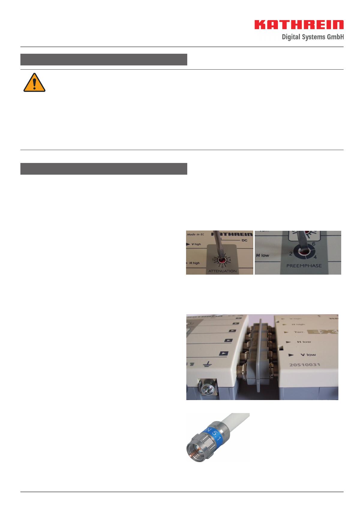
Verstärker einpegeln
Zur Bestimmung des Pegels ist am Besten ein Anten-
nenmessgerät, z. B. MSK130 geeignet. Sie können die
Verstärkung in 1-dB-Schritten zurückregeln (siehe Bild
rechts). Der Dämpfungssteller wirkt jeweils auf alle vier
Verstärkerzüge im Sat-Bereich gleichzeitig.
Zum Ausgleich von Schräglagen der Dämpfung, z. B. bei
großen Kabellängen, ist es möglich, den Verstärker auf eine
Vorentzerrung von 2-, 4- und 6dB einzustellen. Der terrest-
rische Verstärker wird mit einem eigenen Regler eingestellt.
Verstärker mit weiteren Geräten der
Sat-Empfangsanlage verbinden
Die einfachste und schnellste Verbindung, z.B. zu einem
Durchgangsmultischalter, wird mit dem optional erhältli-
chen Steckverbinder EMU 290 hergestellt (Bild rechts).
Hier werden die Geräte direkt aneinandergesteckt.
Bei weiter voneinander entfernten Geräten emp ehlt sich
die Verwendung von hochwertigen Koaxialkabeln (mit sehr
hohen Schirmungswerten), z. B. LCD111 A+.
Wenn möglich, hochwertige F-Stecker (Bild rechts, Self-
Install-Stecker) oder Kompressionsstecker verwenden;
siehe auch Kathrein-Katalog „Kabel und Stecker von
Kathrein – immer eine gute Verbindung“.
4 / 5
ACHTUNG
Bei Verwendung von Koaxialkabeln achten Sie besonders auf die richtige Zuordnung der Ein- bzw. Ausgänge
zueinander. Der Ausgang „V low“ des Verstärkers muss mit dem Eingang „V low“ des Multischalters
verbunden werden usw.
ACHTUNG
Gefahr von Geräteschäden!
Bei größerem Durchmesser des Kabelinnenleiters als 1,2mm bzw. Grat können die Gerätebuchsen zerstört
werden.
Nur Koaxialkabel mit einem maximalen Innenleiterdurchmesser von 1,2 mm und ohne Grat verwenden.
Max. 2 mm
Überstand
Anzugsmoment
max. 3,4 Nm
(Gefahr des
Überdrehens)
Durchmesser
0,6 - 1,2 mm gratfrei
Potenzialausgleich
Für den Potenzialausgleich einen Erdungsdraht von mindestens 4mm Querschnitt
verwenden.
Zur Erdung des Gerätes die am Gerät vorhandene Erdungsschraube verwenden.
Jedes Gerät der Empfangsanlage erden.
Spannungsversorgung des Verstärkers
Der Verstärker wird durch das eingebaute Schaltnetzteil versorgt. Dieses Netzteil versorgt über den Hlow-Anschluss
auch das Speisesystem.
WARNUNG
Lebensgefahr durch elektrische Spannung!
Gerät nicht öffnen oder manipulieren.
Bei Arbeiten an der Anlage immer Netzstecker aus der Steckdose ziehen.
Zum Gerät allseitig einen Abstand von mindestens 5cm einhalten.
Die freie Luftzirkulation um das Gerät sicherstellen, um eine Überhitzung zu vermeiden.
Gerät nicht an der Decke montieren.
VORSICHT
Gefahr durch elektrische Spannung!
Keine mit Flüssigkeit gefüllten Gegenstände auf das Netzteil stellen.
Das Netzteil nicht Tropf- oder Spritzwasser aussetzen.
Der Netzstecker muss leicht zugänglich sein.
Gerät durch Ziehen des Netzsteckers vom Netz trennen.
www.kathrein-ds.com | support@kathrein-ds.com 9363163/d/STM/0320/DE | Änderungen vorbehalten.
KATHREIN Digital Systems GmbH | Anton-Kathrein-Str. 1–3 | 83022 Rosenheim | Deutschland | Telefon +49 731 270 909 70
Anlagenbeispiele (symbolische Darstellung)
KAZ 11/12
UAS
584
KAZ 12
21810002
A
KAZ 11
A
UAS
584
VWS 2900
ESD..
ESC..
ESD..
ESC..
2
T
err.
V
high
H
high
V
low
H
low
1
4
3
6
5
8
7
V
high
H
high
V
low
H
low
Pos
A
Pos
B
1
3
5
7
2
4
6
8
T
err.
V
high
H
high
V
low
H
low
V
high
H
high
V
low
H
low
Pos
A
Pos
B
EXR 2998 | EXR 2908
T
err.
V
low
H
low
18V
T
err.
H
high
V
high
V
low
H
low
18V
V
low
H
low
18V
H
high
V
high
V
low
H
low
18V
Servicestelle
Sollten Sie mit diesem Kathrein-Qualitätsprodukt wider Erwarten Probleme haben, setzen Sie sich bitte mit Ihrem Fach-
händler bzw. mit unserer Servicestelle in Verbindung. Die Anschrift unserer Servicestelle lautet:
autronic electronic-service GmbH
Hauptstr. 2a
35792 Löhnberg-Obershausen
Telefon: +49 6477 6123-101
Fax: +49 6477 6123-020
E-Mail: service-kathrein@autronic-service.de
Vereinfachte EU-Konformitätserklärung
Hiermit erklärt die KATHREIN Digital Systems GmbH, dass das Gerät
VWS 2900, BN: 20510026
der Richtlinie 2014/53/EU entspricht. Der vollständige Text der EU-Konformitätserklärung ist unter der folgenden
Internetadresse verfügbar: www.kathrein-ds.com
Entsorgung
Elektronische Geräte gehören nicht in den Hausmüll, sondern müssen – gemäß Richtlinie 2002/96/EG DES
EUROPÄISCHEN PARLAMENTS UND DES RATES vom 27. Januar 2003 – über Elektro- und Elektronik-Altge-
räte fachgerecht entsorgt werden. Bitte geben Sie dieses Gerät am Ende seiner Verwendung zur Entsorgung an
den dafür vorgesehenen öffentlichen Sammelstellen ab.
1 / 5
About This Guide
This document is part of the product.
Do not install or use the device until you have read and
understood this document.
Perform all operating steps described in this manual in
the speci ed sequence.
Keep this document for reference throughout the ser-
vice life of the device. Pass this document on to any
new owner or user.
For the most up-to-date version of this document, go to
www.kathrein-ds.com.
Features
High dynamic range of ampli er units
High decoupling between the ampli er units
Due to the use of a GaAs  nal stage, the terrestrial
ampli er is suitable for CATV applications
Adjustable attenuators (in 1-dB steps) for the satellite
range and terrestrial range (the ampli er branches for
the satellite range and terrestrial range are adjusted
separately)
Adjustable pre-emphasis (steps of 2/4/6 dB) in the
satellite range (each satellite branch is adjusted sepa-
rately) permits optimum pre-emphasis slope in the
cascade
The power supply to the ampli er units and the LNBs
is provided by an integrated highly ef cient switched-
mode power supply unit
Due to the use of a highly ef cient DC/DC converter,
the power consumption of the VWS 2990 is extremely
low
Suitable for use in Kathrein Sat-IF distribution systems
with 8 x Sat-IF (two satellite positions)
For indoor installation
Scope of Delivery
VWS2900
Instructions for use
Intended Use
The VWS2900 is used solely to amplify satellite and
terrestrial signals in satellite reception systems.
Any use other than that speci ed or failure to observe
these application notes will invalidate the warranty or
guarantee.
Sat IF Distribution System
Multi-switch Distribution Network Amplifi er
Transport and Storage
Transport and store the device in its original packaging.
Transport the device only in the permitted temperature
range between -25 and +70 °C and store it in the range
between –5and +45°C. Make sure there is no water
condensation build-up.
VWS2900 20510026
geeignet für DVB-T/T2
2 / 5
Type VWS2900
Order number 20510026
Inputs 1 x terrestrial 8 x Sat IF
Frequency range MHz 47–862 950–2150
Gain 
)
dB 17–21 22–24
Adjustment range of the adjustable attenuator (1
dB steps)
dB 0–15 0–15
Equalisation setting range dB - 2/4/6
Max. output level (interferences 3rd order) dBµV 113
2)
115
3)
Max. output level (interferences 2nd order) dBµV 104
2)
110
3)
Max. operational level for CATV (up to 862 MHz)
4)
dBµV 98 -
Trunk decoupling dB - 40
Nominal input voltage V 207 – 253 (50 – 60 Hz)
Secondary voltage (input horiz. low) V +18
Available remote feed current (input horiz. low) mA 500
Permissible ambient temperature °C –20 bis +55
Protection class/protection type (insulated) II (double insulated)/IP 30
Connections F-type connectors
Dimensions (W x H x D) mm 285 x 148 x 43
Packing unit/weight (pc./kg) 1 (10)/1,1
1)
Frequency-dependent gain (pre-emphasis) depending on the pre-equalisation setting
2)
60 dB IMA according to EN 60728-3
3)
35 dB IMA according to EN 60728-3
4)
According to EN 60728-3, 60 dB CTB/CSO, CENELEC channel plan
Dimensions in mm
Technical Data
3 / 5
Installation and Safety Instructions
CAUTION
Risk of material damage when operating the device in inappropriate ambient conditions!
Install the device in dry indoor areas only.
Do not install on or against highly combustible materials.
Equip the device with an equipotential bonding conductor (Cu, at least 4mm
2
).
Make sure to comply with the safety regulations set out in the current EN 60728-11 and EN 62368-1
standards.
Cap the ports that are not used (for compliance with the regulations on radiated interference)
Fixings: Wood screws, max. Ø: 4.0mm
Connectors: RF connector 75 Ω (F series) to EN 61169-24.
Installing the Device
Installing the Amplifi er in a Satellite Reception System
The VWS2900 ampli er is used at the input to large multi-switch cascades or as a cascadable distribution network
ampli er for balancing the through losses of cables, splitters or distributors in large distribution networks.
Ensure that the level at the input lies between 50 and max. 80dBµV and that the downstream multi-switches are not
overloaded.
Levelling the Amplifi er
To determine the level, an antenna meter is suited best,
e.g. the MSK130. You can adjust the gain in 1-dB steps
(see  gure on the right). The attenuator affects all four
ampli er units in the satellite range at the same time.
To equalise attenuation slopes, e.g. in long cable lengths,
it is possible to set the ampli er’s pre-equalisation to 2, 4
and 6 dB. The terrestrial ampli er is adjusted with its own
attenuator.
Connecting the Amplifi er to Other Devices
Within the Satellite Reception System
The easiest and quickest way to connect the ampli er
to, e.g. a loop-through multi-switch is to use the optional
connector EMU 290 (see picture on the right).
This enables the devices to be connected to each other
directly.
If the devices are further apart from each other, we recom-
mend using high-quality coaxial cables with very high
screening values, e.g. LCD111 A+.
If possible, use high-quality F-type connectors (picture
on the right, self-installed connectors) or compression
connectors; see also the Kathrein catalogue “Cables and
connectors from Kathrein – always a good connection”.
4 / 5
NOTICE
When using coaxial cables, take particular care to ensure correct assignment of the inputs and outputs. The
Vlow output from the ampli er must be connected to the Vlow input of the multi-switch, etc.
NOTICE
Risk of material damage to the device!
If the inner cable conductor diameter is more than 1.2mm, or if burring is present, the device sockets may be
destroyed.
Only use a coaxial cable with an inner conductor diameter of 1.2 mm max. and without burrs.
Max. 2 mm
Überstand
Anzugsmoment
max. 3,4 Nm
(Gefahr des
Überdrehens)
Durchmesser
0,6 - 1,2 mm gratfrei
Potential Equalisation
For potential equalisation, use an earthing wire of at least 4 mm cross-section.
For earthing the device, use the earthing screw provided on the device.
Earth each unit in the reception system.
Power Supply for the Amplifi er
The ampli er incorporates a switched-mode power supply. Via the H low port, this power supply unit also supplies the
terrestrial ampli er power supply system.
WARNING
Danger to life due to electric shock!
Do not open the device or tamper with it.
When working on the system, always unplug the mains plug from the wall socket.
Maintain a clearance of at least 5 mm all round the device.
To avoid overheating, ensure free circulation of air all round the device.
Do not install the device on the ceiling.
CAUTION
Danger to life due to electric shock!
No liquid- lled items may be placed on top of the power supply unit.
The power supply unit must not be exposed to dripping or splashing water.
The mains plug must be easily accessible.
The device must be disconnected from the mains by unplugging it at the wall socket
www.kathrein-ds.com | support@kathrein-ds.com 9363163/d/STM/0320/GB | Subject to change.
KATHREIN Digital Systems GmbH | Anton-Kathrein-Str. 1–3 | 83022 Rosenheim | Germany | Phone +49 731 270 909 70
System Examples (Symbolic Representation)
KAZ 11/12
UAS
584
KAZ 12
21810002
A
KAZ 11
A
UAS
584
VWS 2900
ESD..
ESC..
ESD..
ESC..
2
T
err.
V
high
H
high
V
low
H
low
1
4
3
6
5
8
7
V
high
H
high
V
low
H
low
Pos
A
Pos
B
1
3
5
7
2
4
6
8
T
err.
V
high
H
high
V
low
H
low
V
high
H
high
V
low
H
low
Pos
A
Pos
B
EXR 2998 | EXR 2908
T
err.
V
low
H
low
18V
T
err.
H
high
V
high
V
low
H
low
18V
V
low
H
low
18V
H
high
V
high
V
low
H
low
18V
Service Centre
If, contrary to expectation, you should have any problems with Kathrein quality products, please contact your specialist
dealer or our service centre. The address of our service centre is:
autronic electronic-service GmbH
Hauptstr. 2a
35792 Löhnberg-Obershausen
Phone: +49 6477 6123-101
Fax: +49 6477 6123-020
E-Mail: service-kathrein@autronic-service.de
SIMPLIFIED EU DECLARATION OF CONFORMITY
Hereby, KATHREIN Digital Systems GmbH declares that the radio equipment type
VWS 2900, order no.: 20510026
is in compliance with Directive 2014/53/EU. The full text of the EU declaration of conformity is available at the
following internet address: www.kathrein-ds.com
Disposal
Electronic equipment is not domestic waste – in accordance with directive 2002/96/EC OF THE EUROPEAN
PARLIAMENT AND THE COUNCIL dated 27th January 2003 concerning used electrical and electronic appli-
ances, it must be disposed of properly. At the end of its service life, take this unit for disposal at a designated
public collection point.
  • Page 1 1
  • Page 2 2
  • Page 3 3
  • Page 4 4
  • Page 5 5
  • Page 6 6
  • Page 7 7
  • Page 8 8
  • Page 9 9
  • Page 10 10

Kathrein 20510026 User manual

Category
TV signal amplifiers
Type
User manual
This manual is also suitable for

Ask a question and I''ll find the answer in the document

Finding information in a document is now easier with AI

in other languages