Page is loading ...

8115F
8115SF
Turn off hot and cold water
supplies before beginning.
CAUTION
Insert FAUCET (1) and CABLE CONNECTOR (2) through center hole
of mounting surface. Fig. A.
From under side of mounting surface thread the two MOUNTING
NUTS (2) onto FAUCET SHANKS (4). Fig. B.
Center FAUCET (1) and hand tighten MOUNTING NUTS (3) to
secure FAUCET (1).
1
Certified to comply with ANSI A112.18.1
Installation
Instructions
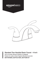
Single Control Centerset Lavatory
Faucet
with Speed Connect™ Drain
INSTALL FAUCET
Adjustable Wrench Screwdriver Channel Locks
Recommended tools
Tubing Cutter
Congratulations on purchasing your American Standard faucet with the
Speed Connect Drain, a feature found only on American Standard faucets.
Speed Connect Drain*
• 1/3 of the parts, installs in 1/3 of the time
• No tools needed
• Never needs adjustment
• Guaranteed to seal properly the first time, every time.
*Your new American Standard faucet is designed to work only with the Speed Connect Drain. Helpful tips for
removing your current drain can be found in the Troubleshooting section of these instructions.
To ensure that your installation proceeds smoothly-please read these instructions carefully before you begin.
Fig. A.
Fig. B.
1
Plumbers' Putty or Caulking
Apply a bead of putty along the edge of the underside of the FAUCET (1).
(HAND TIGHTEN)
3
1
2
4
3
PUTTY
M968797 Rev.1.8
TM

INSTALL POP-UP DRAIN
INSTALL BLACK GASKET
3
2
Install BLACK CONE GASKET (1) onto DRAIN BODY (2)
from below.
Note: The flat side of the BLACK CONE GASKET (1) must
face down.
4
Drop DRAIN BODY (4) through sink drain
hole. Make sure WHITE FOAM GASKET (5)
is under flange of DRAIN BODY (4).
Fig. B.
Note: No plumber’s putty or caulk is required.
The CABLE ATTACHMENT POINT (6) must
face towards the rear of the SINK.
Fig. B.
Remove CLEAR PLASTIC COVER (1). Remove
CARDBOARD SPACER (2) from under DRAIN
POP-UP (3).
Fig. A.
2
REAR OF
SINK
4
5
6
3
1
SINK
DRAIN
HOLE
FLAT SIDE OF GASKET
MUST FACE DOWN
1
2
Fig. A.
2
1
FLAT SIDE OF
GRAY LOCKNUT
MUST FACE UP
INSTALL GRAY LOCKNUT
5
Install GRAY LOCKNUT (1) onto DRAIN BODY (2)
from below SINK. Fig. A.
Note: The flat side of the GRAY LOCKNUT (1)
must face up.
Tighten firmly by hand. No tools are required.
Check DRAIN FLANGE in SINK to ensure that
WHITE FOAM GASKET (3) is fully compressed
and not visible. Fig. B.
POP-UP KNOB (1) must be fully down.
POP-UP KNOB
Fig. A. Fig. B.
DOWN
3
WHITE FOAM
GASKET
NOT VISIBLE
DRAIN
FLANGE
Fig. B.
2
1
M968797 Rev.1.8

Connect HOT water supply to inlet of left SHANK and COLD
water supply to right SHANK using sealant, appropriate
connectors, and COUPLING NUTS.
Connect 1-1/4” O.D. TAILPIECE (4) on POP-UP
DRAIN to
“p” trap.
8
Connect water supply to INLET SHANKS (1) with 1/2" IPS
FLEXIBLE SUPPLIES (2) or 3/8" O.D. BULL-NOSE RISERS (3).
Use adjustable wrench to tighten connections. Do not over
tighten. Be careful not to kink copper supply when bending.
Use tubing cutter to cut to proper length.
MAKE WATER SUPPLY AND WASTE CONNECTIONS
NOTE: FLEXIBLE SUPPLIES OR BULL-NOSE RISERS NOT INCLUDED
AND MUST BE PURCHASED SEPARATELY.
HOT
COLD
FERRULE
COMPRESSION
NUT
COUPLING
NUT WITH
FAUCET
COUPLING
NUT ON FLEX
SUPPLIES
FLEXIBLE
SUPPLIES
1
3/8 O.D.
BULL-NOSE
RISERS
3/8 COMPRESSION
CONNECTION
2
3
Thread CABLE CONNECTOR (1) clockwise
onto DRAIN BODY CONNECTION (2) and
hand tighten. Fig. A.
Your new POP-UP DRAIN installation is
now complete. Fig. B.
Note: Tailpeice on pop-up drain is 1-1/4” O.D.
Fig. B.
Fig. A.
ATTACH CABLE CONNECTOR
6
2
1
Operate LIFT KNOB (1) to verify that STOPPER (2) opens and
closes.
Note: If STOPPER (2) does not open and close properly then refer
to the “troubleshooting section” of these instructions.
CHECK OPERATION OF POP-UP
7
1-1/4” O.D.
Fig. B.
4
3
2
1
“P” TRAP
M968797 Rev.1.8

3
CHECK DRAIN CONNECTIONS
10
11
12
TEST INSTALLED FITTING
With HANDLE (1) in OFF position, turn on WATER
SUPPLIES (2) and check all connections for leaks.
Ensure that AERATOR (3) is tightened completely.
Operate HANDLE (1) to allow water flow.
Operate POP-UP KNOB (5) and fill Sink with water. Check
that DRAIN STOPPER (4) makes a good seal and retains
water in Sink. If STOPPER (4) does not seal properly, please
refer to “Troubleshooting Guide” in these instructions.
Release POP-UP KNOB (5) down and check all drain
connections and "P" trap for leaks. Tighten
if necessary.
5
9
4
CARE INSTRUCTIONS:
DO: SIMPLY RINSE THE PRODUCT CLEAN WITH CLEAR WATER. DRY WITH A SOFT COTTON FLANNEL CLOTH.
DO NOT: DO NOT CLEAN THE PRODUCT WITH SOAPS, ACID, POLISH, ABRASIVES, HARSH CLEANERS, OR A
CLOTH WITH A COARSE SURFACE.
2
1
2
4
“P” TRAP
WASTE
OUTLET
CARTRIDGE INLETS
MANIFOLD
SERVICE
1
2
3
4
If Faucet Drips Proceed As Follows:
Turn VALVE in OFF position.
Remove HANDLE (1), CAP (2) and CARTRIDGE (3).
Clean CARTRIDGE INLETS and MANIFOLD.
Reassemble CARTRIDGE (3), alternately tightening SCREWS (4).
Replace CAP (2) and HANDLE (1). Check flow.
If faucet drips, operate handle several times from "off" to "on".
Do not apply excessive force.
Clogged CARTRIDGE INLETS may cause reduced flow in "full on" hot
or cold. To clean inlets, first turn off water supply, then:
M968797 Rev.1.8

Speed Connect™ Drain
Troubleshooting Guide
1
2
Disconnect the Cable from the Drain by threading the Cable Connector (1) counter-clockwise. Fig. A.
Look at the area on the Drain Body where the Cable was attached and locate the component labeled
as “Cam” and “Cam Cap” in the illustration. Fig. B.
Use fingers or small screwdriver under either side of the Cam Cap to pry it out from the Drain. Fig. D.
Remove the Cam by pulling it straight out while wiggling gently to loosen the Rubber Seal. Fig. E.
The Stopper can now be removed by lifting it out of the Drain. Fig. F.
CAM
CAM CAP
RE-ATTACH
DISCONNECT
CABLE ADJUSTMENT PROCEDURE
If sink does not hold water even though Stopper is in the “down” position:
• Follow CABLE ADJUSTMENT PROCEDURE.
If Stopper does not raise up fully or sink drains too slowly:
• Follow CABLE ADJUSTMENT PROCEDURE.
If you need to remove the Stopper:
• Follow STOPPER REMOVAL PROCEDURE.
If you would like the ability to remove your Stopper simply by lifting it out of the drain:
• Follow STOPPER INSTALLATION PROCEDURE for “Unlocked” mode.
Fig. A.
REMOVE
CAM CAP
REMOVE
CAM
Fig. D.
Fig. F.
Disconnect the Cable from the Drain by threading the Cable Connector (1) counter-clockwise. Fig. A.
Look at the area on the Drain Body where the Cable was attached and locate the component labeled as
“Cam” in the illustration. Fig. B.
Use a small screwdriver to rotate the Cam in the clockwise direction as far as it will go. At this point the
Stopper should be in the UP position. Fig. B, C.
Push DOWN on the Lift-Knob to make sure it is fully down. Fig. C.
Re-attach the Cable to the Drain Body Connection (2) by threading the Cable Connector (1) clockwise onto the
Drain Body Connection (2) and hand-tighten. Fig. A.
STOPPER REMOVAL PROCEDURE
5
Fig. B.
1
DOWN
STOPPER
Fig. C.
Fig. E.
M968797 Rev.1.8

STOPPER INSTALLATION PROCEDURE
Locked Mode:
Look at the Plastic Loop at the bottom of the Stopper and notice
that the Loop is on one side of the Stopper. Fig. G.
To install the stopper in “Locked” mode, insert the Stopper into
the Drain so that the Plastic Loop is facing toward the rear of the
Sink and the American Standard logo is facing front. Rotate
Stopper slightly if necessary so that the Stopper slides all the
way down.Fig. G.
Re-install the Cam into the Drain, rotating the Cam if necessary
to make sure it is fully inserted. Fig. J.
Re-install the Cam Cap, making sure the guide teeth are facing
outward. If the Cam Cap does not “snap” into place, then rotate
the Cam to make sure it is fully inserted. Fig. K.
Re-attach Cable. See “CABLE ADJUSTMENT PROCEDURE” in
Troubling Shooting Guide to complete installation. Stopper will be
in “Locked” mode and not be removable.
Unlocked Mode:
Look at the Plastic Loop at the bottom of the Stopper and notice
that the Loop is on one side of the Stopper. Fig. H.
To install the stopper in “Unlocked” mode, insert the Stopper into
the Drain so that the Plastic Loop is facing toward the front of the
Sink and the American Standard logo is facing rear. Rotate Stopper
slightly if necessary so that the Stopper slides all the way down.
Fig. H.
Re-install the Cam into the Drain, rotating the Cam if necessary
to make sure it is fully inserted. Fig. J.
Re-install the Cam Cap, making sure the guide teeth are facing
outward. If the Cam Cap does not “snap” into place, then rotate
the Cam to make sure it is fully inserted. Fig. K.
Re-attach Cable. See “CABLE ADJUSTMENT PROCEDURE” in
“Troublingshooting Guide” to complete installation. Stopper will be
in “Unlocked” mode and removable.
Fig. J. Fig. K.
INSTALL
CAM CAP
CAM
INSTALL CAM
The Stopper can be installed two ways, “Locked” Mode (Stopper cannot be
removed) or “Unlock” Mode (Stopper is removable).
Unlocked Mode
locked Mode
LOOP TOWARD
FRONT OF SINK
180˚
LOGO
DRAIN
Fig. H.
LOGO
DRAIN
Fig. G.
LOOP TOWARD
REAR OF SINK
6
M968797 Rev.1.8

TIPS FOR REMOVING YOUR OLD DRAIN:
Loosen nuts on P-Trap using channel locks. Suggest spraying nuts with spray lubricant to loosen any corrosion or
debris that may have built up. Remove P-Trap half from Tailpiece. Use bucket to catch any residual water in P-trap.
Unthread Pivot Rod Nut from Drain Body and remove. Pull Stopper out from Drain Body.
Loosen Mounting Nut as far down as it will go. Push Drain Body up into Sink and unthread Flange from Drain Body.
Remove Drain Body from below sink.
Unthread Tailpiece from Drain Body.
Loosen and remove Mounting Nut and Gasket on Drain Body using channel locks. Suggest spraying nut with spray
lubricant to loosen any corrosion or debris that may have built up. Push Drain Body up into the Sink and remove.
Note: If Drain body rotates while loosening Mounting Nut, insert a screw driver into overflow hole to prevent Drain
Body from rotating while Mounting Nut is removed.
Adjustable Wrench Phillips ScrewdriverChannel Locks
Required tools
METAL OR PLASTIC TWO PIECE
DRAIN BODY
METAL DRAIN BODY WITH
PLASTIC TAILPIECE
PLASTIC DRAIN BODY
WITH PLASTIC TAILPIECE
UNTHREAD
FLANGE
STOPPER
WHEN DRAIN IS REMOVED FROM ABOVE SINKWHEN DRAIN IS REMOVED
FROM BELOW SINK
MOUNTING
NUT
MOUNTING
NUT and
GASKET
METAL
DRAIN
BODY
PLASTIC
DRAIN BODY
PLASTIC
TAILPIECE
P-TRAP
HALF
PIVOT
ROD NUT
PIVOT
ROD NUT
SINK
STOPPER
SCREWDRIVER
STOPPER
MOUNTING
NUT and
GASKET
METAL OR
PLASTIC
DRAIN BODY
FINISHED
WALL
FINISHED
WALL
FINISHED
WALL
PLASTIC
TAILPIECE
PIVOT
ROD NUT
SINK SINK
P-TRAP
HALF
P-TRAP
HALF
For Drains that are removed from below Sink:
For Drains that are removed from above Sink:
7
Most existing drains can be removed quickly and easily with only a pair of channel-
lock pliers or a wrench. However, there may be situations where it is difficult to
remove your old drain or determine how the drain is disassembled. Depending upon
the existing Drain in your sink, it is either removed from above or below the sink.
The illustrations below show some typical drain installations and how they are disas-
sembled from the sink.
The following tips can help with some of the more common challenges in drain removal:
M968797 Rev.1.8

MODEL NUMBER
SINGLE CONTROL
CENTERSET FAUCET
with Speed Connect Drain
CADET
8115F
8115SF
M913208-007A
SPONGE WASHER
M962551-0070A
CAM ASSEMBLY
M962431-0070A
DRAIN MOUNTING KIT
M952430-0070A
CABLE ASSEMBLY
M952410-0020A
M952410-2950A
DRAIN ASSEMBLY
8
072574-0070A
EXTENSION
PIVOT ROD S/A
M960991-0070A
CLIP
072531-0070A
RETAINER KIT
M960990-0070A
SEAL
M913815-0070A
TAILPIECE
M919665-0070A
RUBBER GASKET
M913302-0070A
FLANGE
M900986-YYY0A
M900986-YYY0A
STOPPER
M907022-YYY0A
M907022-YYY0A
M950146-0020A
M950146-2950A
POP-UP ROD
OLD DRAIN & POP-UP
ROD BEFORE 06/2006
065800-0070A
ATTACHMENT NUT
M922880-0020A
M922880-2950A
AERATOR
M950158-0020A
M950158-2950A
LIFT ROD
M918506-0070A
CARTRIDGE SCREWS
A951470-0070A
CARTRIDGE
M907301-0020A
M907301-2950A
CAP
M962133-0020A
M962133-2950A
HANDLE KIT
030746-0070A
HANDLE SCREW KIT
Appropriate finish code
CHROME 002
SATIN NICKEL 295
M962543-0020A
M962543-2950A
STOPPER
ASSEMBLY
For toll-free information and answers to your questions, call:
1-800-442-1902
Weekdays 8:00 a.m. to 6:00 p.m. EST
IN CANADA 1-800-387-0369 (TORONTO 1-905-306-1093)
Weekdays 8:00 a.m. to 7:00 p.m. EST
IN MEXICO 01-800-839-1200
Product names listed herein are trademarks of American Standard Inc.
© AS America, Inc. 2008
HOT LINE FOR HELP
M968797 Rev.1.8
M907265-0070A
PLUG BUTTON
/