Snap-On MIG220 Owner's manual
- Category
- Welding System
- Type
- Owner's manual
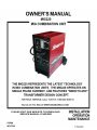
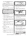
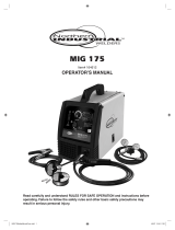
Snap-On MIG220 is a versatile welding machine capable of welding steel, stainless steel, aluminum, bronze, flux-cored, and gasless flux-cored wires. It offers precise control over voltage and wire feed speed, making it suitable for both beginners and experienced welders. The MIG220's compact design and industrial wheel kit ensure portability and maneuverability in various work environments.
Snap-On MIG220 is a versatile welding machine capable of welding steel, stainless steel, aluminum, bronze, flux-cored, and gasless flux-cored wires. It offers precise control over voltage and wire feed speed, making it suitable for both beginners and experienced welders. The MIG220's compact design and industrial wheel kit ensure portability and maneuverability in various work environments.


-
 1
1
-
 2
2
-
 3
3
-
 4
4
-
 5
5
-
 6
6
-
 7
7
-
 8
8
-
 9
9
-
 10
10
-
 11
11
-
 12
12
-
 13
13
-
 14
14
-
 15
15
-
 16
16
-
 17
17
-
 18
18
-
 19
19
-
 20
20
-
 21
21
-
 22
22
-
 23
23
-
 24
24


Snap-On MIG220 Owner's manual
- Category
- Welding System
- Type
- Owner's manual
Snap-On MIG220 is a versatile welding machine capable of welding steel, stainless steel, aluminum, bronze, flux-cored, and gasless flux-cored wires. It offers precise control over voltage and wire feed speed, making it suitable for both beginners and experienced welders. The MIG220's compact design and industrial wheel kit ensure portability and maneuverability in various work environments.
Ask a question and I''ll find the answer in the document
Finding information in a document is now easier with AI
Related papers
Other documents
-
ESAB MXA253 B 3m Torch & MXA254 B 4m Torch Specification
-
 HIT Welding 802276 User manual
-
 HIT Welding 802276 User guide
-
PRO-SERIES MMIG140 User guide
-
 Northern Industrial Tools 164612 User manual
-
 HIT Welding 802054 User manual
-
Craftsman 18851265 Owner's manual
-
Builders Edge 130110004030 Installation guide
-
 HIT Welding 802283 User guide
-
Cebora 584 Jaguar 203 User manual


