Cooper Security Scantronic 9751 User manual
- Category
- Fire protection
- Type
- User manual
This manual is also suitable for

ALARM SYSTEM
USER GUIDE

Page 2 497100, Issue 3
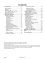
Contents
1. Introduction ........................................3
Alarm System.......................................3
Keypad.................................................4
Proximity Tags .....................................4
723r Telecommand/ 722r PA ...............7
Mains Power Failures...........................7
About this Guide...................................8
2. Everyday Operation ...........................9
Setting the System...............................9
General Procedure.........................10
Timed Set.......................................11
Final Door Set ................................11
Lock Set .........................................11
Terminated Set...............................11
Silent Set........................................11
Instant Set......................................12
Keyswitch Set.................................12
Telecommand Set ..........................12
Forbikobler Keypad Set..................12
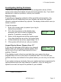
Investigating Setting Problems...........13
Detector Active...............................13
Keypad Display Shows “Bypass
Supr. Z?” ........................................13
Keypad “Locks” ..............................14
Other Problems..............................14
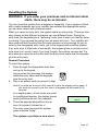
Unsetting the System.........................15
General Procedure ........................ 15
Keyswitch Unset............................ 16
Telecommand Unset ..................... 16
Aborting False Alarms ................... 16
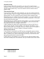
3. After an Alarm.................................. 17
Responding to a Fire Alarm............... 17
Responding to other Alarms .............. 17
4. Special Functions............................ 19
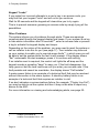
Introduction........................................ 19
Calling Downloader ........................... 19
Viewing Alerts.................................... 20
Omitting Zones .................................. 21
Requiring User Code before
Installer Code .................................... 22
Reading the Log ................................ 22
Turning the Chime On and Off .......... 23
Testing the Sounders ........................ 23
Testing Zones.................................... 24
Setting up Users................................ 24
Access Codes ............................... 25
Proximity Tags............................... 28
Setting Time and Date....................... 28
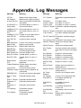
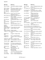
Appendix. Log Messages ................... 29
Notes .................................................... 31
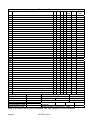
Your Installation .................................. 32
9853, 9752, 9751 Hardwired Control Unit Alarm System User Guide.
This document applies to control panels using software version 4.03.x.
© Cooper Security Ltd. 2006
Every effort has been made to ensure that the contents of this book are correct. However, neither the authors
nor Cooper Security Limited accept any liability for loss or damage caused or alleged to be caused directly or
indirectly by this book. The contents of this book are subject to change without notice.
Printed and published in the U.K.

497100, Issue 3 Page 3
1. Introduction
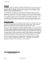
Alarm System
The alarm systems described in this book comprise a control unit (model
9853, 9752 or 9751), one or more keypads, and various detectors. The
control unit houses a main controller, power supply, stand-by battery and
communication device. It is normally fitted in a safe place out of sight (for
example, under the stairs).
The detectors are installed in various places, or zones, around the premises.
If something triggers a detector, the detector signals this to the control unit.
How the control unit reacts depends on whether the system is set or unset.
• When set, the control unit raises an alarm whenever a detector is
triggered. The alarm might be a bell or strobe on the outside of your
premises, or it might be a silent signal over the telephone line to an Alarm
Receiving Centre (ARC).
• When unset, the system does not raise an alarm if a detector is triggered.
Your installer can program the control unit so that your system is either:
• Single system. You can set the system to one of four levels: A, B, C or
D. Level A protects the whole of the premises covered by the detectors.
Levels B, C and D each protect part of the premises while the rest is in
use. You cannot set more than one level at the same time.
• Partitioned system. The premises protected by the system are divided
into four partitions: A, B, C and D. Each partition behaves as a separate
alarm system; it can have its own final exit and entry route zone, and it
can be set and unset independently of other partitions. One or more
partitions may share a common area. You can set one, two, three or four
partitions at the same time.
Whichever type of system you have, the control unit raises an alarm when a
detector in a set level or partition is triggered. Your installer allocates detector
zones to levels or partitions during installation. Refer to the table on page 32
to see if your system is single or partitioned, and how zones are allocated.
Your premises may be fitted with 24-hour zones and panic alarm zones. If
these zones are triggered, the system will raise an alarm even if no level or
partition is set. 24-hour zones are often used to protect emergency fire exits.

1. Introduction
Page 4 497100, Issue 3
Keypad
Your alarm system is fitted with a 9930 or 9940 keypad, from which you can
set and unset the system. Figures 1 and 2 show the main features of these
keypads. Refer to "4. Special Functions" on page 19 for information about
other functions available from them.
The system will not accept commands from the keypad until you identify
yourself with an access code or proximity tag. It can store 50 access codes,
which may contain four or six digits
1
, giving secure access for up to 50 users.
Your installer may have set up your system to hide status information
2
. If so,
the display and lamps show no information until you identify yourself. This
prevents status information being used to compromise system effectiveness.
Proximity Tags
So that you do not have to remember access codes, your installer may have
fitted your keypads with a device that reads proximity tags. These tags are
small slips of plastic that have electronic circuitry built into them.
When you hold a tag against a suitably equipped keypad, the circuit inside the
tag emits a radio code that the keypad reads. Each tag has a unique code. If
the alarm system recognises the tag, it allows you to do almost anything that
you could do with an access code. If the tag is not recognised, you cannot use
the alarm system. When presenting a tag to a 9930 keypad, make sure that it
is touching the sensitive area to the left of the display (Figure 1). The 9940
keypad has a proximity coil that makes the whole case sensitive to tags.
You can program the system to recognise up to 49 tags. U01, the master
user, can only be assigned an access code – a proximity tag cannot be
assigned to this user. For instructions, refer to page 27.
1
Installer Command 56
2
Installer Command 28

1. Introduction
497100, Issue 3 Page 5
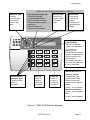
Figure 1. 9930 LCD Remote Keypad
Alert lamp (see page 20)
Flashes to highlight
unacknowledged alarm,
fault or tamper conditions.
Glows for acknowledged
conditions.
Goes out when all
conditions are rectified.
Service lamp
Glows if the
system needs
an Installer
reset.
Mains lamp
Glows when
using mains
power.
Flashes when
using stand-by
battery.
Sensitive area
Present
proximity tags
by touching
them to this
area.
2-line 16-digit liquid
crystal display
The first line shows:
- unset: time and date
- set: level(s) or
partition(s) set.
The second line shows
Installer-configured text,
often the control unit
model number.
The display may show
only time and date until
a user is identified.
Exit key
Press to
cancel a
command
sequence.
Enter key
Press to
confirm a
command
sequence.
IMPORTANT NOTE
Dual key alarms
Pressing two keys
together can initiate
alarms if these are
enabled (see page 32).
Panic
Press 1 and 3 together.
Medical assistance
Press 4 and 6 together.
Fire
Press 7 and 9 together.
These may show nothing until a user is identified.
Level/partition
selection keys
Press to select
levels or
partitions.

1. Introduction
Page 6 497100, Issue 3
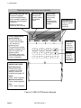
Figure 2. 9940 LCD Remote Keypad
AB CD
123
456
7890
Alert lamp (see page 20)
Flashes to highlight
unacknowledged alarm,
fault or tamper conditions.
Glows for acknowledged
conditions.
Goes out when all
conditions are rectified.
Service lamp
Glows if the
system needs
an Installer
reset.
Mains lamp
Glows when
using mains
power.
Flashes when
using stand-by
battery.
2-line 16-digit liquid
crystal display
The first line shows:
- unset: time and date
- set: level(s) or
partition(s) set.
The second line shows
Installer-configured text,
often the control unit
model number.
The display may show
only time and date until
a user is identified.
Exit key
Press to
cancel a
command
sequence.
Enter key
Press to
confirm a
command
sequence.
IMPORTANT NOTE
Dual key alarms
Pressing two keys
together can initiate
alarms if these are
enabled (see page 32).
Panic
Press 1 and 3 together.
Medical assistance
Press 4 and 6 together.
Fire
Press 7 and 9 together.
These may show nothing until a user is identified.
Level/partition
selection keys
Press to select
levels or
partitions.

1. Introduction
497100, Issue 3 Page 7
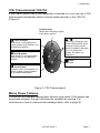
723r Telecommand/ 722r PA
If your alarm system has a radio expander connected to it, you can use a 723r
telecommand (sometimes called a remote setting device) or the 722r PA
(Figure 3).
Figure 3. 723r Telecommand
Mains Power Failures
The control unit indicates mains power failures using alerts. If the supply has
since been restored, the alert will show the condition as inactive. For
instructions on how to view and acknowledge alerts, refer to page 20.
Transmit lamp
Glows when sending a signal
to the alarm system.
Level A button
Sets Level A (full system) in a
single system; sets Partition A in
a partitioned system.
Level B button
Sets Level B in a single system;
has no effect in a partitioned
system.
Unset button
Unsets Level A (full system) in a
single system; unsets Partition
A
in a partitioned system.
+
(722r only) Pressing Level
A
and Unset buttons at the
same time starts a panic
alarm (if enabled, see page
32). In a partitioned
system, the alarm is in
Partition A.
button
Not used.

1. Introduction
Page 8 497100, Issue 3
About this Guide
The rest of this guide tells you how to use the system:
2. Everyday Operation Tells you how to set and unset the system.
3. After an Alarm Tells you how to switch off the sounders after an
alarm, view what caused the alarm and reset the
system so that it can be used again.
4. Special Functions Tells you how to use more advanced features, some
of which are available only to the master user.

497100, Issue 3 Page 9
2. Everyday Operation
During installation, your installer programs the system to create an exit route
and entry route for your premises. When setting the system, you must follow
the exit route. When unsetting the system, you must follow the entry route. If
you stray from these routes, you may cause a false alarm.
Setting the System
There are several different methods for setting the system. Each level or
partition can use a different method, although not all methods are available in
all cases. Your installer will have selected the methods that suit your site
best
3
.
The possible setting methods are:
Timed Set Instant Set
Final Door Set Keyswitch Set
Lock Set Telecommand Set
Terminated Set Forbikobler Keypad Set
Silent Set
The setting procedure is similar for each method and shown on page 10.
Subsequent sections describe the specifics of each setting method.
If you try to set the system while something is triggering a detector in the
protected area (for example a door or window is still open), the system will not
set (see page 13).
If you find that your detectors generate false alarms immediately after you
leave the premises, this may be because they are detecting air movements
when the exit door is closed. You may need to ask your installer to increase
the Final Exit Settling Time
4
.
3
Installer Commands 39, 62, 72 and 76
4
Installer Command 182

2. Everyday Operation
Page 10 497100, Issue 3
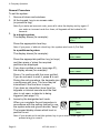
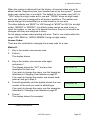
General Procedure
To set the system:
1. Secure all doors and windows.
2. At the keypad, key in an access code
(or present a tag).
Note:If you enter an incorrect code, press
X
to clear the display and try again. If
you enter an incorrect code four times, all keypads will be locked for 90
seconds.
3.
In a single system:
The display shows (for example):
System OK
Set?
Press the appropriate level key.
Note: If you press
y
without a level key, the system sets Level A (Full Set).
In a partitioned system:
The display shows (for example):
System OK
Set? ABCD
Press the appropriate partition key (or keys)
and then press y when the required
partitions are displayed.
4. If you have omitted a zone (see page 21),
the display shows (for example):
Omit Zone 03?
Set? ABCD
Press y to continue with the zone omitted.
If you do not want to omit it, press X to exit.
During the exit procedure, the keypads give
a continuous exit tone. The tone may be
intermittent if the final door is open.
Setting ABCD 009
If you hear an intermittent tone from the
keypads or internal sounder and the final
door is not open, a detector is being
triggered (see page 12).
5. Leave by the designated exit route.
When you complete the exit procedure in
accordance with the setting method in use,
the system sets and gives a double "beep".
The keypad display shows which level or
partition is set.
Set ABCD
9x5x
Set A
9x5x
Note: If you decide not to set the system, key in your access code again (or
present a tag) to unset it.

2. Everyday Operation
497100, Issue 3 Page 11
Timed Set
With Timed Set, the system sets after a programmed exit time has expired.
The time starts when you press a level key in a single system or y in a
partitioned system, or when you press y to accept an omitted zone. Your
installer will have made the exit time long enough for you to leave the
premises and secure the final door
5
.
When using Terminated Set (see below), your installer may have
programmed the system to set after the exit time even if the exit terminate
button is not pressed. This ensures your premises are protected if you forget
to press the button.
Final Door Set
Your installer may have programmed the system so that closing the final door
completes the setting sequence. The system sets 7–12 seconds
6
after you
secure the final door. There is no fixed exit time.
Lock Set
Your installer may have fitted a special lock so that locking the final door
completes the setting sequence. The lock contains a switch so that the control
unit can sense whether the lock is open or closed. The system sets seven
7
seconds after you lock the final door. There is no fixed exit time.
Note: Lock Set is available only for Level A (Full Set) in a single system.
In a partitioned system, any partition may be Lock Set.
Terminated Set
Your installer may have fitted an exit terminate button. This is usually outside,
beside the final door, and you press it when you leave. The system sets
seven
8
seconds after you press the button. There is no fixed exit time.
Silent Set
Some levels or partitions on your system may be programmed for Silent Set.
The system does not give an audible warning when it sets these but it gives a
double "beep" at the end of the exit time to show that it is set.
Note: Silent Set is not available for Level A (Full Set) in a single system.
In a partitioned system, any partition may be Silent Set.
5
Installer Commands 44, 65, 75 and 79
6
Installer Command 182
7
Installer Command 182
8
Installer Command 182

2. Everyday Operation
Page 12 497100, Issue 3
Instant Set
The area protected by a level or partition may not need an exit route or final
door. With Instant Set, the system sets as soon as you press the appropriate
key, without waiting for an exit time. The system gives a double "beep" to
show that it is set.
Note: Instant Set is not available for Level A (Full Set) in a single system.
In a partitioned system, any partition may be Instant Set.
Keyswitch Set
If your system is fitted with a keyswitch, you can use it to set the system. If it
is a three-position keyswitch in a single system, you can use it to set Level B.
The keyswitch initiates setting, which then completes in accordance with the
programmed exit mode. You do not need to enter an access code or present
a tag.
Note: In a partitioned system, you can set only Partition A.
Telecommand Set
If your system is fitted with a radio expander and your installer has enabled
the appropriate option, you can use a telecommand to set the system. If it is a
single system, you can use the telecommand to set Level B.
The telecommand initiates setting, which then completes in accordance with
the programmed exit mode. You do not need to enter an access code or
present a tag.
Figure 3 on page 7 shows the actions of the buttons on the telecommand.
Note: In a partitioned system, you can set only Partition A.
Forbikobler Keypad Set
Your system may be programmed to use a special type of entry or exit zone
called a Forbikobler zone. The word "forbikobler" means "bypass" in Danish.
These zones are used to connect external keypads or access controllers.
If an exit is programmed as a Forbikobler zone with an external keypad, a
trigger from the keypad within the exit time stops the timer and sets the
system.

2. Everyday Operation
497100, Issue 3 Page 13
Investigating Setting Problems
This section offers general guidance but the configurable nature of 9x5x
control units means that details of each alert and response vary. If you need
assistance to resolve a problem, contact your installer.
Detector Active
If something is triggering a detector at the end of the exit procedure, the
system will not set. Depending how your installer has set up the system
9
,
internal or external sounders may operate. The display shows which zone (or
zones) is active.
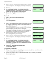
To set the system:
1. Enter your access code (or present your tag) to
silence any sounders.
2. Go to the zone shown on the display (see
example) and find out what is triggering the
detector. If possible, remedy the fault.
Zone Open Z03
Zone 03
3. Return to the keypad and set the system again.
If no other detectors are active, the system sets.
4. If other detectors are active, repeat steps 1 to 3.
5. If the system still will not set, call your installer.
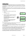
Keypad Display Shows “Bypass Supr. Z?”
If you see the message at the right on your keypad
display when you are trying to set the system, then
one or more of your radio based detectors has a
problem. Press Y.
Bypass Supr. Z?
Active Set?
If the display reverts to the time and date then your system has been
programmed not to set in the event of a detector fault. You must call your
installer and they must attend to the system before you can carry on and use
it.
If you system carries on and sets, then your system has been programmed to
ignore problems with the radio detector in question. Carry on using your
system as normal, but report the problem to your installer.
9
Installer Command 27

2. Everyday Operation
Page 14 497100, Issue 3
Keypad “Locks”
If you make four incorrect attempts in a row to key in an access code, you
may find that your keypad “locks” and will not let you continue.
Wait for 90 seconds and the keypad will clear allow you to try again.
This is to prevent someone guessing an access code by simply trying all the
possibilities.
Other Problems
The system informs you of problems through alerts. These are warnings
communicated through the keypad display and lamps. If your system is set up
to hide status information after 30 seconds
10
, enter an access code or present
a tag to activate the keypad display and lamps.
Depending on the nature of the problem, you may need to reset the system or
call an installer to do this for you (see page 17). Your installer may have set
up your system to enable you to override some faults
11
, in which case you will
be able to set the system while the fault is still present. If the display shows
"Set" underneath the alert message, press y to continue with setting.
If an installer reset is required, the control unit lights the s lamp and the
keypad sounds a repeating "beep" to warn you. If the fault disappears, the
lamp goes out but the tone continues until you enter your access code. If the
fault persists and cannot be overridden, the display shows "Call Installer".
A mains power failure is an example of a technical fault that may be resolved
without intervention in the alarm system. A stand-by battery failure is an
example of a technical fault that requires an installer to visit.
If an alert indicates a communications failure (for example, "Plugby Line Fail"),
you may be able to set the system but then it may not be able to report any
alarms to the ARC.
For more information on viewing and acknowledging alerts, see page 20.
10
Installer Command 28
11
Installer Commands 134 to 140

2. Everyday Operation
497100, Issue 3 Page 15
Unsetting the System
WARNING: If you enter your premises and an internal alarm
starts, there may be an intruder.
You can unset the system from a keypad or keyswitch. If your system is fitted
with a radio expander and your installer has enabled the appropriate option,
you can also unset it with a telecommand.
When you open an entry door, the system starts an entry timer. There are four
entry timers so that different entrances can use different times. During the
entry time, the keypads give a "galloping" entry tone to warn you that the timer
is running. If you exceed the entry time, an alarm will occur. Your installer will
have ensured that the entry time for each entrance is long enough for you to
enter by the designated entry route, get to the keypad and unset the system.
If an entry door is fitted with a lock switch, the keypad gives a continuous exit
tone when you unlock it and, if you lock it again, the system remains set; it is
only when you open the entry door that the entry timer starts and the keypads
give the entry tone.
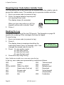
General Procedure
To unset the system:
1. Enter through the designated entry door
and go to the keypad.
As you enter the premises, the system
starts the entry timer and the keypads
give the entry tone.
2. Key in an access code (or present a tag).
Note:If you enter an incorrect code, press
X
to clear the display and try again. If
you enter an incorrect code four times, all keypads will be locked for 90
seconds.
In a single system, all set levels are unset.
In a partitioned system, the display shows
which partitions are set (for example):
Unset? AB D
9x5x
3. Press the appropriate partition key (or
keys) if required, followed by y.
The entry tone stops and the system
gives a double "beep".
The system or partition is now unset.

2. Everyday Operation
Page 16 497100, Issue 3
Keyswitch Unset
If your system is fitted with a keyswitch, you can use it to unset Level or
Partition A. With a three-position keyswitch, switching from Part to Off unsets
Level B (single system only). You do not need to enter an access code or
present a tag.
Telecommand Unset
If your system is fitted with a radio expander, you can use a telecommand to
unset the system. Figure 3 on page 7 shows the actions of the buttons on the
telecommand. You do not need to enter an access code or present a tag.
Depending how your installer has set up the system
12
, you may be able to use
the telecommand to unset the system from outside the premises. In this case,
the entry time will not be used.
Depending how your installer has set up the system
13
, you may be required to
use the telecommand for unsetting. If you attempt to enter an access code,
the keypad will show the message "Locked Out".
If after unsetting the system with a telecommand you hear an alert tone (a
gentle "beep") and see "Tcmd Low Batt" on the keypad, the battery in your
telecommand needs to be changed. Enter your access code at the keypad to
silence the alert tone. Ask your installer to change the battery.
Aborting False Alarms
If your system is connected to an ARC and you accidentally cause an alarm,
you normally have at least two minutes before the ARC calls the police. Alarm
Abort
14
enables you to cancel a false alarm by entering a valid access code
during this period (which is set by the ARC).
If Alarm Abort is not enabled on your system and you often exceed an entry
timer that is already set to the maximum, ask your installer about Alarm Abort.
12
Installer Command 129
13
Installer Command 48
14
Installer Command 36

497100, Issue 3 Page 17
3. After an Alarm
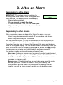
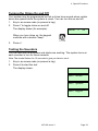
Responding to a Fire Alarm
IMPORTANT: The system gives a fire alarm by
sounding a two-tone warning from the keypads and
alarm sounder. The display shows (for example):
Fire Z02 Alarm
9x5x
1. Evacuate the premises.
Do not attempt to unset the alarm.
2. If there is evidence of fire, call the Fire Brigade.
3. Only when the premises are safe, proceed as for
other alarms.
Responding to other Alarms
When your system raises an alarm other than a fire alarm, you must:
• Unset the system as normal to switch off the sounders and strobes.
• Reset the system ready for further use.
Note: In a partitioned system, you may not have access to unset all partitions but
entering your access code (or presenting your tag) will silence all sounders.
The system logs the zone (or zones) that triggered the alarm and displays
alerts on the keypad display. The first zone is shown automatically when you
unset the system. View the others by pressing Y to accept the Next prompt.
For instructions on viewing and acknowledging alerts, see page 20.
Your system may be configured for various types of reset:
• User reset. Enter your access code (or present your tag) again to reset
the system. The system gives a double "beep" to confirm that it has reset.
• Installer reset. If the display shows "Call Installer", contact your alarm
company to arrange a visit.
• Remote reset. If the display shows a reset code, write down the code
and call your ARC. You will be asked to verify your identity, the
circumstances and the code. If no intervention is required from an
installer, you will be given a code to enable you to reset the system.

3. After an Alarm
Page 18 497100, Issue 3
Your installer may have enabled a guard, which is someone who is authorised
to unset the system only after an alarm
15
.
Your installer may have set up your system to dial a number in an alarm and
send a "beep"
16
. Up to 15 calls may be made to confirm the alarm
17
. If you
have a 9853 control unit (see page 32), the person taking the call can press 5
on the telephone keypad to acknowledge the notification and stop further
calls. With other models, the full sequence of calls must be completed.
15
Installer Command 181
16
Installer Command 103
17
Installer Command 186

497100, Issue 3 Page 19
4. Special Functions
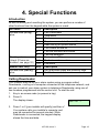
Introduction
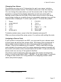
As well as setting and unsetting the system, you can perform a number of
other functions from the keypad while the system is unset:
All Users Key Description
0 Call Downloader
1 View alerts
2 Omit zones
3 Require user code before installer code
5 Read the log of system events
7 Turn chime on and off
8 Test the sounders and strobe
Access code (or tag)
plus:
9 Test the detectors
1+3 Panic alarm (PA)
4+6 Medical assistance alarm
Dual key alarms
(check if these are
enabled, see page 32)
7+9 Fire alarm
Master User Only Key Description
4 Set up access codes and proximity tags
Access code (not tag)
plus:
6 Set the time and date
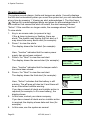
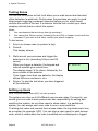
Calling Downloader
Your installer may set up your alarm system using a program called
Downloader, running on a computer connected to the telephone network, and
ask you to instruct your alarm system to telephone Downloader using one of
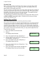
two numbers programmed into the control unit. To start the call:
1. Key in an access code (or present a tag).
2. Press 0.
The display shows:
Call CS ?
3.
Press 1 or 2 (your installer will specify) and then y.
Your system calls your installer's computer and
may be connected for several minutes. While
Downloader is connected, the keypad display
shows the time and date.

4. Special Functions
Page 20 497100, Issue 3
Viewing Alerts
The system records alarms, faults and tampers as alerts. It usually displays
the first alert automatically when you unset the system but you can view alerts
at any time by pressing 1. Viewing an alert acknowledges it. The Alert lamp
(
) flashes for unacknowledged alerts and glows for acknowledged alerts. If
the condition that caused the alert still exists, the alert message shows
"Active". If the condition no longer exists, the message shows "Inactive".
To view alerts:
1. Key in an access code (or present a tag).
If the
lamp is glowing or flashing, there are
alerts. The system may display the first alert or it
may show how many alerts exist (for example):
3 Problem(s)
Set? ABCD
2. Press 1 to view the alerts.
The display shows the first alert (for example):
MAINS Fail
Inactive Next
Here, "Inactive" indicates that the mains power
supply has since been restored.
3. Press
y for "Next" to view the next alert.
The display shows the second alert (for example):
Lid Tamper
Inactive Next
Here, "Inactive" indicates that the tamper switch
has since been closed.
4. Press
y for "Next" to view the next alert.
The display shows the third alert (for example):
Battery Missing
Active Next
Here, "Active" indicates that the battery is still
missing. The s lamp will also be lit and there will
be an intermittent audible warning.
If you have viewed all alerts and installer action is
required (for example, to fit a new battery), the
display shows:
Call Installer
9x5x
5.
In this case, contact your alarm company.
If you have viewed all alerts and no installer action
is required, the display shows date and time (for
example):
18/04/2005 14:45
9x5x
6.
In this case, use the system as normal.
Page is loading ...
Page is loading ...
Page is loading ...
Page is loading ...
Page is loading ...
Page is loading ...
Page is loading ...
Page is loading ...
Page is loading ...
Page is loading ...
Page is loading ...
Page is loading ...
-
 1
1
-
 2
2
-
 3
3
-
 4
4
-
 5
5
-
 6
6
-
 7
7
-
 8
8
-
 9
9
-
 10
10
-
 11
11
-
 12
12
-
 13
13
-
 14
14
-
 15
15
-
 16
16
-
 17
17
-
 18
18
-
 19
19
-
 20
20
-
 21
21
-
 22
22
-
 23
23
-
 24
24
-
 25
25
-
 26
26
-
 27
27
-
 28
28
-
 29
29
-
 30
30
-
 31
31
-
 32
32


Cooper Security Scantronic 9751 User manual
- Category
- Fire protection
- Type
- User manual
- This manual is also suitable for
Ask a question and I''ll find the answer in the document
Finding information in a document is now easier with AI
Related papers
-
Cooper Security Scantronic 9651 User manual
-
Cooper Security 9651PD User manual
-
-
Cooper Security i-on160EX User guide
-
-
-
-
Cooper M1000 User manual
Other documents
-
-
Scantronic 9448+ User manual
-
-
-
Risco Gardtec GT480 User Instructions
-
 C&K systems S802 Installation guide
-
Challenger AP200 Engineer Manual
-
Eaton i-on Series Administration And User Manual
-
Pyronix Paragon Plus User Instructions
-
