Page is loading ...

MAN 195C
Digi-Wave
™
300 Series
DLT 300 Digital Transceiver and DLR 360 Digital Receiver
USER MANUAL
DLT 300 DLR 360
The Digi-Wave 300 Series is not backward compatible with previous Digi-Wave transceivers or receivers.

DigiWave 300 Series Digital Transceiver and Receiver
2
Contents
Safety Warnings and Recycling Instructions ............................................................................................................................. 3
System Overview ..................................................................................................................................................................... 4
DLT 300 Controls and Connectors .......................................................................................................................................... 5
DLT 300 Operation .................................................................................................................................................................. 5
Button Functions .............................................................................................................................................................. 5
DLR 360 Controls and Connectors ..........................................................................................................................................7
DLR 360 Operation ................................................................................................................................................................. 7
Getting Started: Preprogrammed Systems .............................................................................................................................. 8
Before Programming the Digi-Wave™ System ......................................................................................................................... 9
Programming the Digi-Wave™ System for 1-way Modes ....................................................................................................... 11
Programming the Digi-Wave™ System for 2-way Modes ....................................................................................................... 12
Programming the Digi-Wave™ System: Optional Settings .................................................................................................... 13
Example 1: 2-way Mode, Tour Guide .................................................................................................................................... 16
How it works .................................................................................................................................................................. 16
2-Way Setup for Tour Guide Operation ........................................................................................................................... 17
Example 2: Simultaneous Interpretation (1-way) ....................................................................................................................19
How it works .................................................................................................................................................................. 19
1-way setup for Simultaneous Interpretation ...................................................................................................................20
Example 3: Intercom (2, 3, 4, 5 or 6 simultaneous talkers) ..................................................................................................21
How it works .................................................................................................................................................................. 21
2-way setup for Intercom ...............................................................................................................................................22
Example 4: Repeater Mode ................................................................................................................................................... 23
Repeater Mode setup .................................................................................................................................................... 23
Dierences between DLT 300, DLT 100 2.0 and DLT 100 ...................................................................................................... 25
Dierences between DLR 360, DLR 60 2.0 and DLR 60 ........................................................................................................26
Dierences between DLT 100, DLT 100 2.0, and DLT 300 rmware versions ......................................................................... 26
Specications ........................................................................................................................................................................ 27
DLT 300 Transceiver ....................................................................................................................................................... 27
DLR 360 Receiver .......................................................................................................................................................... 28
Testing and Certication ........................................................................................................................................................ 29
Troubleshooting ..................................................................................................................................................................... 29
FAQs ..................................................................................................................................................................................... 30
FCC statements .................................................................................................................................................................... 31
2-year Warranty ..................................................................................................................................................................... 32
Digi-Wave™ 300 Series
DLT 300 Digital Transceiver and DLR 360 Digital Receiver

DigiWave 300 Series Digital Transceiver and Receiver
3
Safety Warnings and Recycling Instructions
HEARING SAFETY
CAUTION!
This product is designed to amplify sounds to a high volume level which could potentially cause hearing damage if used
improperly. To protect your hearing and the hearing of others:
(1) Turn the volume down before putting on the earphone or headphone, and then adjust the volume to a comfortable level,
(2) Set the volume level at the minimum setting that you need to hear,
(3) if you experience feedback (a squealing or howling sound), reduce the volume setting and move the microphone away from the
earphone or headphone, and (4) Do not allow children or other unauthorized persons to have access to this product
MEDICAL DEVICE SAFETY
CAUTION!
1. Before using this product with an implantable or other medical device, consult your physician or the manufacturer of your
implantable or other medical device.
2. If you have a pacemaker or other medical device, make sure that you are using this product in accordance with safety
guidelines established by your physician or the implantable device manufacturer.
BATTERY SAFETY
CAUTION!
DLT 300 internal battery pack.
To reduce the risk of re or burns, do not attempt to open, disassemble, or service the battery pack. Do not crush, puncture,
short contacts or dispose of in re or water. Do not incinerate or expose to temperatures above 140F (60C). Replace only with
battery pack designated for this product. Rechargeable Lithium-polymer battery (Li-Po). Recycle or dispose of properly.
CAUTION!
The lithium batteries used in the DLT provide great performance and long life. But, like all lithium batteries, they do have a limited
number of charge/discharge cycles. Lithium batteries may experience swelling if used beyond their expected lifecycle (2 years).
If you notice swelling of the battery, please discontinue use and have the battery replaced. We recommend battery replacement
after 2 years of use. For more information about replacing the battery, please visit our website at:
http://www.williamssound.com/digiwave-battery-replacement.
RECYCLING INSTRUCTIONS
Battery Safety and Disposal
Help Williams Sound protect the environment! Please take time to dispose of your equipment properly. Please do NOT
dispose of batteries in the household trash. Please take the batteries to a retail or community collection point for recycling.
Product Recycling:
Please do NOT dispose of your Williams Sound equipment in the household trash. Please take the equipment to an
electronics recycling center or return the product to the factory for proper disposal.

DigiWave 300 Series Digital Transceiver and Receiver
4
System Overview
The Digi-wave™ system is a patented, digital spread-spectrum (DSS), simultaneous two-way wireless listening system
operating in the 2.4 GHz band. Due to it’s frequency-hopping algorithm, it avoids interference and is a very secure method of
communication. For a more detailed explanation of how Digi-wave technology works, please visit our website and download the
“Digi-wave™ Technology White Paper” (under “Support – Downloads - Tech Bulletins”).
A Digi-Wave communication system consists of at least one transceiver (DLT 300 ) and various combinations of transceivers and
receivers (DLR 360 ) depending on the venue.
The DLT 300 is a 2-way transceiver, meaning that it can transmit and receive audio simultaneously. It can operate in one of 3
dierent modes:
1. In Two-way Mode, a speaker (with a DLT 300) can hear another speaker’s voice (from a second DLT 300) and, at
the same time, can also transmit their own voice. In this way, two-way communication is established (similar to a phone
conversation). Two-way mode can only be established between DLT 300 units. In addition, DLR 360 receivers in the
same group can also hear the broadcast.
2. In One-way Mode, one DLT 300 acts as a transmitter (speaker) and another DLT 300 acts as a receiver (listener). In
addition, DLR 360 receivers in the same group can also hear the broadcast. There are 4 one-way modes.
3. In Repeater Mode, the DLT 300 receives audio from another DLT 300 and re-broadcasts the signal to increase the
transmitted range of the person speaking. In this way, larger groups can be covered by using one or more DLT 300’s
acting as repeaters. Listeners can have either DLT 300’s or DLR 360’s to listen to the broadcast.
4. In Intercom Mode, up to six people can talk simultaneously. All of the DLT 300’s are in 2-way mode in the same
group. More DLT’s can be in the group, but only six can have live mics at the same time (the seventh DLT who wishes
to speak pushes their TALK button and knocks the sixth talker o). DLR’s can listen-in on the conversation if desired.
The Repeater function only operates in 1-way mode. It is not available in a 2-way scenario.
The DLR 360 is a receiver only. Users of receivers can only hear what is being broadcast by DLT(s).
Combinations of one or more DLT 300’s and DLR 360’s in One-way mode, Two-way mode, or Repeater mode can be used to
facilitate dierent events, depending on what needs to be spoken and what needs to be heard. Examples of scenarios will be
covered here.
Typical Scenarios include:
Guided Tours - with one or more tour guides (2-way), with audience participation (2-way), or without audience participation (1-way)
Language Interpretation - one or more interpreted languages transmitted to audience (1-way)
Intercom - with up to six people able to speak simultaneously (2-way)
Note: there are many more scenarios than are covered in this manual, however these would be variations on the ones discussed
here. Rules of Operation for 1-way or 2-way mode must be followed for successful operation.
Note: for simplicity, throughout the rest of this manual, the DLT 300 may be referred to as a “DLT” and the
DLR 360 may be referred to as a “DLR”. Similarly, Master 1, Master 2 and Guest may be referred to as “M1”,
“M2”, and “GST”.
The Digi-Wave 300 Series is not backward compatible with previous Digi-Wave transceivers or receivers.

DigiWave 300 Series Digital Transceiver and Receiver
5
DLT 300 Controls and Connectors
INTERNAL SPEAKER
LCD DISPLAY
A540
LED INDICATORS
TALK BUTTON WITH
RAISED BRAILLE DOT
VOLUME / SELECT UP
VOLUME / SELECT DOWN
POWER / MENU
HEADPHONE JACK 3.5 MM
MICROPHONE JACK 3.5 MM
INTERNAL MICROPHONE
DOCKING / CHARGING
CONNECTOR 30-PIN
DLT 300 Operation
BUTTON FUNCTIONS
POWER / MENU BUTTON
· Press and hold for power On/O
· Press once to change section when in setup menu
· Review setup (push repeatedly to advance to next setting)
· Attendance checking can only be done with a Master unit. Must have address assigned between 1 — 99 to allow
attendance checking function. To check attendance, push and release the
button and the number of attendees
will be displayed for 2 seconds.
QUICK GROUP CHANGE / SETUP BUTTONS
· Press and hold and together for 3 seconds to enter setup menu
· Press and hold button for 3 seconds to enter quick group change mode. The GRP light will ash. Then use
or to change groups. To exit, push again or just wait until the unit times out.
· Use these buttons to select channels in simultaneous interpretation mode

DigiWave 300 Series Digital Transceiver and Receiver
6
MICROPHONE LEVEL ADJUSTMENT
· Hold the
button for two seconds to enter mic level adjustment. For level adjustment use or
LINE LEVEL ADJUSTMENT
· Hold the
button for two seconds to enter mic level adjustment. For level adjustment use or
TONE ADJUSTMENT
· Press and hold the – and + buttons simultaneously for 2 seconds. The LCD will display the last tone setting t: (1 - 9).
· Using the -/+ buttons , adjust the tone up or down: 1 = Most bass 5 = Flat (Default) 9 = Most treble
· Press and hold the – and + buttons simultaneously for two seconds to save the tone setting.
VOLUME CONTROL / SELECT BUTTON
· Control / Volume
· Use to navigate selections in setup menu.
· Access and adjust tone control (0-53)
TALK BUTTON
· Press button momentarily once to activate the microphone. Press button once more to turn o the microphone
· Press and hold the button for approximately 2 seconds to mute other DLT 300 Guest units. Only the M1 and M2 have this
function.
([TALK] LED will blink on all units when in mute mode).
FIRMWARE VERSION
· To check the version of rmware installed in the unit, push the power button repeatedly until “F-x” is displayed; “x” represents
the rmware version of the unit.
Battery Charging – DLT 300
1. This Product uses an internal rechargeable Lithium Polymer battery.
2. Use the 30 Pin connector, located on the bottom of DLT 300 to charge the battery. Full charging time is approximately
12 hours. The Red LED ashes while charging. The Green LED will be on steady when the battery is charged.
3. Battery Maintenance - Charge the battery at room temperature.
CAUTION!
The lithium batteries used in the DLT provide great performance and long life. But, like all lithium batteries, they do have a limited
number of charge/discharge cycles. Lithium batteries may experience swelling if used beyond their expected lifecycle (2 years).
If you notice swelling of the battery, please discontinue use and have the battery replaced. We recommend battery replacement
after 2 years of use. For more information about replacing the battery, please visit our website at:
http://www.williamssound.com/digiwave-battery-replacement.

DigiWave 300 Series Digital Transceiver and Receiver
7
DLR 360 Controls and Connectors
A539
RED LED
GREEN LED
CHANNEL/
GROUP ADJUST
VOLUME ADJUST
ENCENDIDO
HEADPHONE
JACK 3.5 MM
SPEAKER
BATTERY
STRENGTH
BATTERY TYPE
SWITCH
LANYARD SLOT
CHARGING/
DOCKING
CONNECTOR
30-PIN
STRENGTH DLT NO. 1
STRENGTH DLT NO. 2
NUMERIC DISPLAY
NUMERIC TYPE
ANTENNA
SYMBOL
BATTERY
COMPARTMENT
DLR 360 Operation
1. Insert 2 AAA batteries into the DLR. Observe correct polarity. You can use either Alkaline or NiMH, but make sure the battery
switch is in the NiMH position to charge NiMH batteries. If Alkaline batteries are used, put the battery switch in the ALK position.
2. Power on/o by holding the power button for 3 seconds.
3. In 1-way mode, the DLR will seek active DLTs; press channel button up or down to seek next active DLT. In 2-way mode,
group must be selected.
4. The Antenna Symbol will ash, and there will be no Signal Strength Bars, if not synchronized with a DLT.
5. If the units are synchronized, briey push the power button
to show group assigned (0 to 99).
6. To change group, hold the and buttons for 3 seconds until “GROUP” is ashing.
7. Use or buttons to select group number.
8. Hold
and
buttons for 3 seconds again to save the group number.
9. To change volume level press or buttons, display will show 00 through 30.
10. User can listen using the speaker on the back of the DLR or by plugging in stereo or mono earphones into the jack (which
defeats the speaker operation).
11. Low battery indicator will show as a blinking battery symbol with no bars inside it.
12. The DLR will automatically power down after 5 minutes if not synchronized with a DLT.
FIRMWARE VERSION
· To check the version of rmware installed in the unit, push the power button repeatedly until “F-x” is displayed; “x” represents
the rmware version of the unit.
Battery Charging – DLR 360
1. This Product can charge AAA NiMH batteries in the battery compartment when the battery switch is in the NiMH position.
2. Use the 30 Pin connector, located on the bottom of DLR 360 to charge the battery. Full charging time is approximately
5 hours. The Red LED ashes while charging. The Green LED will be on steady when the battery is charged.
3. Battery Maintenance - Charge the battery at room temperature.
A539
RED LED
GREEN LED
CHANNEL/
GROUP ADJUST
VOLUME ADJUST
ENCENDIDO
HEADPHONE
JACK 3.5 MM
SPEAKER
BATTERY
STRENGTH
BATTERY TYPE
SWITCH
LANYARD SLOT
CHARGING/
DOCKING
CONNECTOR
30-PIN
STRENGTH DLT NO. 1
STRENGTH DLT NO. 2
NUMERIC DISPLAY
NUMERIC TYPE
ANTENNA
SYMBOL
BATTERY
COMPARTMENT

DigiWave 300 Series Digital Transceiver and Receiver
8
Getting Started: Preprogrammed Systems
If a system has been purchased, you should not need to perform any programming. The system will have been congured to your
order. Turn Master 1 on rst so other units can pair. Guest units will turn o after 5 minutes if they cannot nd a master.
1. Charge all DLTs. If using DLRs, either charge them with NiMH batteries or insert fresh Alkaline batteries. Make sure the battery
switch is in the correct position for “Alkaline” or “NiMH”. Any DLRs that will be used should have fresh batteries.
2. Identify and turn on the Master 1 rst, usually identied by a grey silicone cover. Turn on the DLT by holding the power button
until the LCD screen comes on. If Master 2 or Guests are powered up rst they will turn o after a few minutes if not paired
with the M1. As Master 2 and Guests are paired with the M1 the M1 and M2 will show C-#. The # refers to how many DLTs are
paired within the group, i.e. C-12 means that 12 DLTs are paired with the M1 or M2 within their group. This can be utilized as
an attendance checker making sure everyone is connected with the group.
3. Once all the DLTs are on, you can check the set-up status of all units by pressing the power/menu button momentarily to scroll
through the settings:
Master 1 and Master 2 screens will display:
C-6 (Chairman plus six = number of participants within the group).
ADD Address number (0 – 1023). Each DLT must have its own individual address.
Group number (0 – 1023) must be the same number for the group.
CODE Only shows if a code has been entered (code number will NOT be displayed).
“F-#” Denotes software version.
Time Displays the time of day.
All Guest units will display:
Address Number
Group Number
Secure Key Code (if entered)
Software Version
Time of Day
4. If headsets are to be worn, plug them into the jacks on the top of the DLTs making sure that the Microphone and Earphone
plugs are fully inserted into the correct jacks.
5. The Master 1 will usually be the rst speaker and should press the talk button momentarily to activate the microphone. This will be
conrmed by the red LED around the talk button illuminated. If the talk LED is ashing, the talk button was held too long and the
talk mute has been activated in the system. Hold the talk button until the LED’s stop ashing to deactivate talk mute.
6. The Master 2 and all Guest units should now be hearing audio from the M1 unit. Listening volume levels can be adjusted by
pressing the – or + button. One other DLT can activate the Talk button for team tour or teach applications. A maximum of two
talkers can be activated at any one time. For a Guest unit to talk, either the M1 or M2 will have to turn their talk button o by
quickly pressing their talk button.

DigiWave 300 Series Digital Transceiver and Receiver
9
Before Programming the Digi-Wave™ System
Depending upon the mode chosen, up to six people can talk in a group at any given time. The M1 will have rst priority, M2 has
second priority and Guest units have third priority. When two or more people are talking in a group, the participants can hear their
voices with the DLTs or DLRs.
The M1 and M2 have the ability to lock out other talkers by holding down the TALK button for three seconds. All system TALK
LEDs will continuously ash while other participants are locked out of the TALK feature.
There are 4 basic steps to programming a Digi-Wave system.
1. Decide which mode you need.
A. 2-Way Modes
In 2-way mode, DLTs can hear and talk to each other, just like having a phone conversation or a conference call. DLRs can
listen to the conversation. Common applications include: Tours with multiple Tour Guides, Tours with audience participation
(Q&A), Wireless Intercom, Portable Discussion and Personal Communication.
There are two 2-way Modes represented by these symbols on the LCD Display:
2-way:
(4 simultaneous talkers maximum)
2-way - Intercom:
(6 simultaneous talkers maximum)
Rules of Operation (2-way modes)
The following rules must be followed. Failure to adhere to these rules will result in unpredictable, unsupported operation.
• There must be one, and only one Master 1 (M1) per group.
• If the M1 unit is o, the Master 2 and Guest units will turn o after a few minutes.
• Master 2 is optional and there can only be one per group.
• Each DLT must have its own address and the address cannot be duplicated within a group.
• Maximum 4 talkers (in 2-way mode) or 6 talkers (in 2-way Intercom mode) can operate simultaneously within a group.
• Maximum four Groups can operate simultaneously within the same area, but each group must be assigned its own group
number.
• When using four simultaneous groups, group numbers must be sequential. i.e. 11, 12, 13, 14. Any numbers 0-1023 can
be used (or 0-99 if DLRs are used in the system).
• Attendee count will only work with addresses 1-99 (Maximum 100 DLT’s with one Master 1 at address 0).
• With Secure Key Code active, all DLTs within the group must have the same 4-digit code entered. (DLRs will not work
with secured DLTs)
B. 1-Way Modes
In 1-way mode, communication ows in one direction. It ows from the main speaker’s DLT, to secondary DLTs or DLR’s. If
repeater mode is used, the repeater DLTs listen to the primary DLTs and transmit to DLTs and DLRs assigned to the same
Group/Channel. The most common applications are: Simultaneous Interpretation with one or more interpreters, or Tours
without audience participation (no Q&A).
There are (4) 1-way Modes represented by these symbols on the LCD Display:
1-way - Main Speaker:
(talks on Channel 0)
1-way - Interpreter:
(receives on Channel 0, speaks on Channel designated for their language)
1-way - Repeater Mode:
(Units out of range of the primary unit(s) receive their broadcast from these units)
1-way - Listen Only:
(receive the broadcast from either the primary units or the repeater units, depending on range)

DigiWave 300 Series Digital Transceiver and Receiver
10
Rules of Operation (1-way modes)
The following rules must be followed when setting up any Digi-Wave™ system. Failure to adhere to these rules will result in
unpredictable, unsupported operation.
• Up to 15 channels can be used simultaneously, i.e. one oor and 14 interpreters.
• There must be one Master 1 (usually this is also the oor), and only one, per group.
• Each Interpreter must be assigned their own channel number.
• Repeater function can only be used in 1-Way mode.
• When repeater function is used, all 15 channels can be utilized in one-way mode, i.e. one oor and 14 interpreters.
• When repeaters are used, Floor (channel 0) must be assigned as the master unit for the group. All other DLTs have to be
assigned as “GST”.
2. Decide Speaking Priority for each DLT.
There are 3 levels of priority. The M1 has rst priority, M2 has second priority and Guest units have third priority. The M1 or M2
will have to turn OFF their talk access to allow the Guest units to talk. When 2-6 people are talking in a group the participants can
hear their voices in the DLTs or DLRs.
The M1 and M2 have the ability to lock out other talkers by holding down the TALK button for three seconds. All system TALK
LEDs will continuously ash while other participants are locked out of the TALK feature. The Master 1 can override anyone else
talking within the group. Master 2 has talking priority over Guests.
Speaker priority is assigned as follows:
1st priority — Master 1 ( M1 ):
2nd priority — Master 2 ( M2 ):
3rd priority — Guest ( GST ):
3. Decide what Address(es) you will need.
Each DLT transceiver must have a unique address. Refer to the “Rules of Operation” (under Step 1) for the mode you are using, to
determine how you will address the units.
4. Decide what Group(s) you need.
Each set of people who want to talk and/or listen to each other must be in the same group. Up to 4 Groups can operate
simultaneously within range of each other.

DigiWave 300 Series Digital Transceiver and Receiver
11
Programming the Digi-Wave™ System for 1-way Modes
There are 4 basic steps to programming a Digi-wave system:
1. Set Mode: 2-way or 1-way
2. Set Priority: Master 1, Master 2, and Guest
3. Set Channel
4. Set Group Number
Most of the programming is done on the DLT(s); the receivers just need to be assigned the correct group number. The Master 1
should be programmed rst - all other units synchronize with the Master 1.
Step 1. Set Mode: 1-way
a. With the DLT turned on, press and hold the and buttons until the icons on the display begin ashing.
b. Use either of the the buttons to scroll through the dierent icon combinations (modes).
c. When you reach the 1-way mode you are looking for (below), go to step 2.
1-way - Main Speaker:
1-way - Interpreter:
1-way - Repeater Mode:
1-way - Receive or Listen Only:
Step 2. Set Priority: Master or Guest
a. Push the button to advance to the priority setting.
b. Use either of the the buttons to scroll through the dierent priorities. Speaker priority is assigned as follows:
1st priority — Master: (Must have one master per group)
2nd priority — Guest: (All other units in the group)
c. When you reach the priority you want, go to the next step.
Step 3. Set Channel
a. Push the button to advance to the address setting. “CH” will ash and the current address will be displayed.
b. Use either of the the buttons to change the address.
Step 4. Set Group Number
a. Push the button to advance to the group setting. “GROUP” will ash and the current group will be displayed.
b. Use either of the the buttons to change the group.
c. All units operating together should have the same group number.

DigiWave 300 Series Digital Transceiver and Receiver
12
Programming the Digi-Wave™ System for 2-way Modes
There are 4 basic steps to programming a Digi-wave system:
1. Set Mode: 2-way or 1-way
2. Set Priority: Master 1, Master 2, and Guest
3. Set Address
4. Set Group Number
Most of the programming is done on the DLT(s); the receivers just need to be assigned the correct group number. The Master 1
should be programmed rst - all other units sychronize with the Master 1.
Step 1. Set Mode: 2-way
There are (3) 2-way Modes represented by these symbols on the LCD Display:
2-way:
2-way - Listen only:
2-way - Intercom:
a. With the DLT turned on, press and hold the and buttons until the icons on the display begin ashing.
b. Use either of the the buttons to scroll through the dierent icon combinations (modes).
c. When you reach 2-way mode, the icon(s) will be ashing (alternately). Go to step 2.
Step 2. Set Priority: Master 1, Master 2, and Guest
a. Push the button to advance to the priority setting.
b. Use either of the the buttons to scroll through the dierent priorities. Speaker priority is assigned as follows:
1st priority — Master 1 ( M1 ) : (Must have one per group)
2nd priority — Master 2 ( M2 ) : (Optional)
3rd priority — Guest ( GST ) : (All other units in the same group)
c. When you reach the priority you want, go to the next step.
Step 3. Set Address
a. Push the button to advance to the address setting. “ADD” will ash and the current address will be displayed.
b. Use either of the the buttons to change the address.
c. Each unit must have a dierent (unique) address assigned.
Step 4. Set Group Number
a. Push the button to advance to the group setting. “GROUP” will ash and the current group will be displayed.
b. Use either of the the buttons to change the group.
c. All units operating together should have the same group number..

DigiWave 300 Series Digital Transceiver and Receiver
13
Programming the Digi-Wave™ System: Optional Settings
DLT Secure Key Code:
When a group has been set up and the same Secure Code has been entered into all the DLTs, the DLTs without this Secure
Code entered cannot listen in on the group. This may be desirable in private or high security-level functions.
The same four digit code must be programmed into all of the DLTs, Master 1, Master 2 and Guests. If a dierent secure code has
been entered, participants cannot re-enter the group without re-entering the correct secure code. The only time the Secure Code
is displayed is when it is being entered. To block users from entering the set-up mode, refer to the SET-UP LOCK (SLOC) feature
(below).
1. Choose a 4 digit numerical code; i.e. 1357. You must use the same code on each DLT in the
group.
2. Start with the Master 1 when programming.
3. With the DLT turned on, hold the and buttons simultaneously for two seconds to
enter the set-up menu.
4. Use the menu button to scroll through the menu pages until you get to the screen displayed
in gure 1.
5. The rst dash will be blinking (gure 1); using the button, enter rst digit of the code (0 – 9).
6. Press the menu button again to move to the second dash which will now be blinking.
7. Enter the next digit and continue until all four digits have been entered.
8. One more press of the menu button and you will see the word CodE displayed (gure 2).
9. With the Secure Key Code entered, exit the set-up menu by holding the and buttons simultaneously for two
seconds.
10. Follow the same process with the Master 2 and Guest units.
NOTE: There will be fewer pages to scroll through on the Master 2 and Guest units to get to the code set-up screen.
DLT Set-Up Lock (SLOC)
Set-up Lock enables the Administrator to prevent unauthorized changes to the system set-up on the DLT.
NOTE: Each DLT has to be locked and unlocked individually.
1. Press twice, then twice (
^
-
^
-v-v). This has to be done within 5 seconds. ‘SLOC’ will
appear momentarily on the screen (gure 3). SLOC is now enabled.
2. When SLOC is enabled, if a user tries to change any setting by entering the set-up mode, ‘SLOC’ will
appear momentarily on the screen. See gure 3.
3. To unlock this feature, the same (
^
-
^
-v-v) sequence must be entered. There will be no prompt
showing that SLOC was disabled. Accessing the set-up mode is the indication that SLOC is disabled.
NOTE: Each DLT has to be locked and unlocked individually.
FIGURE 1
FIGURE 2
Secure Key Code fig. 1
Original (save)
Secure Key Code fig. 2 SLOC fig. 3 Tone Control fig. 4 Quick Group Change fig. 5
Ptt & PnL fig. 6 Ptt & PnL fig. 6
Side Tone fig. 7
A530
Secure Key Code fig. 1
Original (save)
Secure Key Code fig. 2 SLOC fig. 3 Tone Control fig. 4 Quick Group Change fig. 5
Ptt & PnL fig. 6 Ptt & PnL fig. 6
Side Tone fig. 7
A530
FIGURE 3
Secure Key Code fig. 1
Original (save)
Secure Key Code fig. 2 SLOC fig. 3 Tone Control fig. 4 Quick Group Change fig. 5
Ptt & PnL fig. 6 Ptt & PnL fig. 6
Side Tone fig. 7
A530

DigiWave 300 Series Digital Transceiver and Receiver
14
DLT Attendee Checking
When the M1 presses the MENU button once, the number of Guest devices connected to the system will be displayed for two
seconds. Addresses 0 - 99 must be used for attendee checking feature. Addresses over 99 will not be registered. ie: C 12 = 12
DLTs synched with M1.
DLT Tone Control
1. With the DLT powered ON, press and hold the – and + buttons simultaneously for 2 seconds.
2. The LCD will display the last tone setting t: (1 - 9). See Figure 4.
3. Using the -/+ buttons , adjust the tone up or down:
1 = Most bass response 5 = Flat (Default) 9 = Most treble response
4. Press and hold the – and + buttons simultaneously for two seconds to save the tone setting.
DLT Address Conrmation
Press MENU three times for M1 and M2, or twice for GST units. The address for the DLT will be displayed for two seconds.
NOTE: Every DLT MUST have its own address and all must be assigned to the same group.
DLT Quick Group Change
“Groups” apply to 2-way Mode only.
1. With the DLT powered ON, push and hold the Group button until the GROUP indicator on the screen starts blinking and the
light above the Group button comes on (Figure 5).
2. Change groups by pushing the Up button or the Down button . If no buttons are pushed, the Quick Group Change
feature will time out after 5 seconds.
3. Push the Group button once to exit the Quick Group Change function, or wait for 5 seconds.
DLT Push-to-Talk (Ptt) and Push-and-Latch (PNL)
This feature allows the user to choose between Push and Latch (PnL) or Push to Talk (Ptt). The default is PnL.
In PnL mode, when the TALK button is pressed and released, it stays in talk mode until the TALK button is pressed and released
again.
In Ptt mode, the TALK button must be held down while speaking, and when released, it shuts o.
The DLT must be set up as a Guest unit, in 2-way mode, prior to performing these steps.
1. With the DLT powered ON, press and hold the Up button and the Down button simultaneously for 2 seconds to enter
programming mode.
2. Push the Power/Menu button until the TALK indicator is ashing and either “PnL” is or “Ptt” is displayed. (Figure 6).
3. Use either of the -/+ buttons to switch between “PnL” and “Ptt”
4. Press and hold the Up button and the Down button simultaneously for 2 seconds to exit programming mode.
DLT Side Tone Adjustment
This gives the user the ability to change the volume of their own voice heard in the headset (side tone).
1. With the DLT powered ON, press and hold the Up button and the Down button simultaneously
for 2 seconds to enter programming mode.
2. Push the Power/Menu button until “St:” is displayed. See Figure 7.
FIGURE 5
Secure Key Code fig. 1
Original (save)
Secure Key Code fig. 2 SLOC fig. 3 Tone Control fig. 4 Quick Group Change fig. 5
Ptt & PnL fig. 6 Ptt & PnL fig. 6
Side Tone fig. 7
A530
FIGURE 4
Secure Key Code fig. 1
Original (save)
Secure Key Code fig. 2 SLOC fig. 3 Tone Control fig. 4 Quick Group Change fig. 5
Ptt & PnL fig. 6 Ptt & PnL fig. 6
Side Tone fig. 7
A530

DigiWave 300 Series Digital Transceiver and Receiver
15
FIGURE 7
Secure Key Code fig. 1
Original (save)
Secure Key Code fig. 2 SLOC fig. 3 Tone Control fig. 4 Quick Group Change fig. 5
Ptt & PnL fig. 6 Ptt & PnL fig. 6
Side Tone fig. 7
A530
3. Use either of the -/+ buttons to choose between Stt:0 (O), St:1 (-6dB) (default), or St:2 (-12dB).
4. Press and hold the Up button and the Down button simultaneously for 2 seconds to exit
programming mode.
DLT Microphone Level or Line Level Adjustment
To enter Microphone Level Adjustment, hold the
button for two seconds. To enter Line Level
Adjustment, hold the
button for two seconds. Then use or buttons to adjust the level.
DLT Time Display
The time function is available in 2-way or 2-way Intercom Modes only. The Master Unit (M1) can determine
whether the time of day is displayed on all units in the group. When this feature is enabled, all units sync
their time from the Master. To enable time display: Start with the M1 unit powered o. While holding the
TALK button , power the M1 unit ON. Time will now be displayed on all units in the group. Repeat this procedure to disable time
display on all units in the group.
DLT Talk “O” Double-Beep Indication Limit
The user hears an audible “double-beep” sound when the TALK button is turned o. This is heard in the
headset of the user only; it is not transmitted. On the DLT 300, as the headset volume is increased, the beep
volume will increase until the headset volume reaches 37, then the beep volume will stop increasing. (Note:
On the DLT 100 model, the beep volume continued to get louder as the headphone volume was increased,
with no limit.)
DLR Set-Up Lock (SL) (Feature available on rmware version 4 and greater only)
Set-up Lock enables the Administrator to prevent unauthorized GROUP changes on the DLR.
NOTE: Each DLR has to be locked and unlocked individually.
Locking the unit (Setting SL)
1. Hold and together to enter setup mode. The GROUP indicator will start blinking.
2. Press , then (
^
-
^
-v-v) . ‘SL’ will appear momentarily on the screen, then disappear. SLOC is now
enabled.
When SLOC is enabled, if a user tries to change GROUP, ‘SL’ will appear momentarily on the screen, indicating that the unit is
locked. While in SLOC mode, the user can still adjust volume.
Unlocking the unit (Disabling SL)
1. Press , then (
^
-
^
-v-v). “SL” will be displayed. This allows setup mode to be entered, but does not
yet unlock the unit.
2. Within 3 seconds of step 1, hold and together to enter setup mode. The GROUP indicator will start blinking.
3. Hold and together to exit setup mode. ‘SL’ will appear momentarily on the screen, then disappear. Set-up lock
(SL) is now disabled.
Note: Step 1 allows setup mode to be entered - but the act of entering, then exiting setup mode (steps 2 & 3) completes the
unlocking process.
NOTE: Each DLR has to be locked and unlocked individually.
FIGURE 6
Secure Key Code fig. 1
Original (save)
Secure Key Code fig. 2 SLOC fig. 3 Tone Control fig. 4 Quick Group Change fig. 5
Ptt & PnL fig. 6 Ptt & PnL fig. 6
Side Tone fig. 7
A530
Secure Key Code fig. 1
Original (save)
Secure Key Code fig. 2 SLOC fig. 3 Tone Control fig. 4 Quick Group Change fig. 5
Ptt & PnL fig. 6 Ptt & PnL fig. 6
Side Tone fig. 7
A530

DigiWave 300 Series Digital Transceiver and Receiver
16
Example 1: 2-way Mode, Tour Guide
HOW IT WORKS
1. Tour Guide 1 speaks, using a DLT alone (built-in mic) or using it with a compatible headset mic.
2. Each Tour Group Member and Tour Guide 2 listen directly to Tour Guide 1, each using a DLT alone (built-in speaker) or using it
with a compatible headset mic.
3. Tour Guide 2 then speaks, using a DLT alone (built-in mic) or using it with a compatible headset mic.
4. Each Tour Group Member and Tour Guide 1 listen directly to Tour Guide 2 using a DLT.
5. With the push of a button, a Tour Group Member uses a DLT (built-in mic) to ask the Tour Guides a question. Both Tour Guides
and all Tour Group Members listen to the question, each using a DLT.
6. Tour Guide 2 responds to the question, using a DLT. Tour Guide 1 and all Tour Group Members listen to the answer, each using
a DLT.
7. Tour Guide 1 responds to the same Tour Group Member question. Tour Guide 2 and Tour Group Members now listen to Tour
Guide 1’s answer, each using a DLT.
8. Tour Guides have two-way communication capability; they can talk/listen simultaneously to one another. Tour Group Members
can participate as listen-only or can ask questions with the quick push of a button. Tour Guides have the ability to take control
of the discussion by overriding Group Member (Guest) units, if needed.

DigiWave 300 Series Digital Transceiver and Receiver
17
A558
TOUR GUIDE 1
TOUR GUIDE 2
TOUR GROUP
2-WAY
2-WAY
Master Unit
Original (save)
Guest Unit(s)
A541
Intercom Setup:
Tour Guide 1 Unit
2-way Tour Guide Setup:
Tour Guide 2 Unit
Tour Group Member Units
2-WAY SETUP FOR TOUR GUIDE OPERATION
1-way
Speak Only
(Main Speaker)
1-way
Receive / Speak
(Interpreter)
1-way
Repeater
1-way
Receive Only
2-way
Intercom
2-way
(Tour Guide)
1-way Modes
1-way
Speak Only
(Main Speaker)
1-way
Receive / Speak
(Interpreter)
1-way
Repeater
1-way
Receive Only
2-way
Intercom
2-way
(Tour Guide)
1-way Modes
2-way Modes
1-way
Speak Only
(Main Speaker)
1-way
Receive / Speak
(Interpreter)
1-way
Repeater
1-way
Receive Only
2-way
Intercom
2-way
(Tour Guide)
1-way Modes
2-way Modes
1-way
Speak Only
(Main Speaker)
1-way
Receive / Speak
(Interpreter)
1-way
Repeater
1-way
Receive Only
2-way
Intercom
2-way
(Tour Guide)
1-way Modes
2-way Modes
2-way Modes
A536

DigiWave 300 Series Digital Transceiver and Receiver
18
1
A533
32 4
5 6 87
2-way Tour Guide Setup
9 10 11 12
13 14 15 16
17 18 19
Press and hold POWER
button for 2 seconds
to turn DLT ON
Press and Hold and
for 3 seconds to enter
programming mode.
The other icons will disappear
and the current mode icon
will be blinking on the screen.
Use the buttons
to change to 2-way Tour
Guide mode.
Press the button to
select this mode and move
to the next setting.
The ADDRESS icon will be
blinking. Use the
buttons then the button
to choose address (0-1023).
Use the buttons
to select Master 1 (first unit
only). There must be only
one Master 1 per group.
Press the button to
select this mode and move
to the next setting.
The TIME icon will be blinking
with the hour. Use
then the button to
choose hour (am or pm).
The GROUP icon will be
blinking. Use the
buttons then the button
to choose group.
The TALK icon will be
blinking. Use the
buttons then the button
to choose the number of
simultaneous talkers.
The Sidetone Level will be
blinking. Use the
buttons then the button
to choose the Sidetone Level.
The TIME icon will be blinking
along with the minutes. Use
the buttons to
adjust the minutes.
Press the button to
save the time and move
to the next setting.
The first secure code digit
will be blinking. Use
to adjust the first digit.
Push to advance to the
next digit.
Repeat steps 15 and 16
until all of the digits are
adjusted. Push .
The currently selected mode
will be blinking. This is the
beginning of programming.
Press and Hold and
for 3 seconds to exit
programming mode.

DigiWave 300 Series Digital Transceiver and Receiver
19
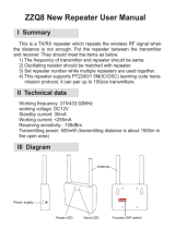
Example 2: Simultaneous Interpretation (1-way)
HOW IT WORKS
1. The Main Speaker will use channel 0; Press the TALK button to activate the microphone
2. Each Interpreter unit will need to be assigned a channel number (1-14). The TALK button must be activated to send the
interpretation to the attendees.
3. The oor speaks, using a DLT alone (built-in mic) or using it with a compatible headset mic.
4. Interpreter listens directly to the oor, using a DLT alone (built-in speaker) or using it with a compatible headset mic.
5. With the push of a button, interpreter simultaneously interprets to the listeners, using a DLT alone (built-in mic) or using it with a
compatible headset mic.
6. Each listener hears the interpretation using a DLR.
An additional DLT can be set-up as a repeater to increase the range of each channel. The Repeater Function can only be used in
simultaneous interpretation mode. See section “Repeater Mode” for details.
The 3.5mm stereo microphone jack can accept a headphone level or a line level output from audio sources when using the
Williams Sound WCA 094 attenuated cable.
A559
INTERPRETER
Listening on Ch. 0
Speaking on Ch. 1
(French)
INTERPRETER
Listening on Ch. 0
Speaking on Ch. 2
(Spanish)
INTERPRETER
Listening on Ch. 0
Speaking on Ch. 3
(German)
THE AUDIENCE
LISTENS ON THE
CHANNEL FOR
THEIR LANGUAGE
Listening
Ch. 3
German
Listening
Ch. 0
English
Listening
Ch. 1
French
In this scenario, all Interpreters listen to the main speaker on Ch. 0.
Each interpreter speaks their interpretation on a separate channel.
The audience listens to the channel for the language they want to hear..
ALL INTERPRETERS
ARE LISTENING TO
THE MAIN SPEAKER
ON CHANNEL 0
EACH INTERPRETER
SPEAKS/TRANSMITS
ON A DIFFERENT
CHANNEL
Listening
Ch. 2
Spanish
MAIN SPEAKER/
FLOOR
Speaking on Ch. 0
(English)

DigiWave 300 Series Digital Transceiver and Receiver
20
1-WAY SETUP FOR SIMULTANEOUS INTERPRETATION
1-way
Speak Only
(Main Speaker)
1-way
Receive / Speak
(Interpreter)
1-way
Repeater
1-way
Receive Only
2-way
Intercom
2-way
(Tour Guide)
1-way Modes
1-way
Speak Only
(Main Speaker)
1-way
Receive / Speak
(Interpreter)
1-way
Repeater
1-way
Receive Only
2-way
Intercom
2-way
(Tour Guide)
1-way Modes
2-way Modes
1-way
Speak Only
(Main Speaker)
1-way
Receive / Speak
(Interpreter)
1-way
Repeater
1-way
Receive Only
2-way
Intercom
2-way
(Tour Guide)
1-way Modes
2-way Modes
1-way
Speak Only
(Main Speaker)
1-way
Receive / Speak
(Interpreter)
1-way
Repeater
1-way
Receive Only
2-way
Intercom
2-way
(Tour Guide)
1-way Modes
2-way Modes
2-way Modes
A536
A534
1-way Simultaneous Interpretation Setup
1 32 4
5 6 87
9 10 11 12
13 14 15
Press and hold POWER
button for 2 seconds to
turn DLT ON.
Press and Hold and
for 3 seconds to enter
programming mode.
The other icons will disappear
and the current mode icon
will be blinking on the screen.
Use the buttons
to change to 1-way
Simultaneous Interpretation
mode.
Press the button to
select this mode and move
to the next setting.
The GROUP icon will be
blinking. Use the
buttons, then the button
to choose group.
Use to select
Master (first unit only). There
must be only one Master
per group. Press . .
Push to advance to the
next digit.
The TIME icon and hour will
be blinking. Use the
buttons then the button
to choose hour (am/pm).
The minutes will be blinking.
Use to adjust, then
to choose the minute.
Repeat steps 11 and 12 until
all four digits are adjusted.
Press to advance to
the next setting.
The first secure code digit will
be blinking. Use to
adjust the first digit. Press
to advance to the next digit.
The currently selected mode
will be blinking. This is the
beginning of programming.
Press and Hold and
for 3 seconds to exit
programming mode.
The CH icon will be
blinking. Use the
buttons, then the button
to choose channel 0 (first unit).
/