Page is loading ...

10B
10A
9A
9B
9C
8A
8C
3D
3A
3B
3C
10.Connect water supply
lines (10A) to faucet inlets
(10B). (supply lines are not
included.)
9
7
8
8.Place spout assembly (8A)
onto spout body (8B) and
secure with set screw (8C).
6.Insert T-tube (6A) onto spout
shank (6B) until it is completely
seated. Place clip (6C) through
slots (6D).
5.Place spout body (5A)
through mounting hole in
deck. Secure spout with
rubber washer (5B), metal
washer (5C) and nut (5D).
Tighten nut (5D) securely
with wrench.
3.From underneath the deck, insert
valve body with rubber washer (3A),
metal washer (3B) and mounting nut
(3C) through holes on the right (cold)
side. From above, thread flange seat
(3D) onto valve body. Tighten
mounting nut (3C), so that the flange
seat (3D) sits flush to the surface of
working area. Then insert the other
valve body through holes on the left
(hot) side and install in the same way.
NOTE: HOT side end valve is labeled.
2.Remove the index (2A)
and unscrew the screw (2B),
then remove the handle
assembly (2C). Unscrew the
flange (2D) from flange seat
(2E). Unthread flange seat
(2E) from valve body (2F).
Many of these parts come
preassembled. This exploded
diagram is to assist in trouble
shooting.
TROUBLE SHOOTING
Problem:
Leak from under handle.
Cause:
Damaged cartridge.
Action:
Remove handle. Replace cartridge.
Problem:
Leak from spout.
Cause:
Damaged or dirty seals.
Action:
Disassemble faucet, remove
cartridge. Clean or replace it.
8~16"
3" min.
5" min.
1-3/8"
1-1/8"
9.Connect the flexible water
supply hose (9A) to the bottom
of valve bodies (9B) as show.
Align T-tube (9C) in a position
which will allow maximum
clearance to connect hoses.
Carefully bend the hoses to fit
available space. Carefully
thread the hose couplings to
the sides of the T-tube (9C).
11.Important: After installation
is completed, remove aerator.
Turn on water supply and
allow both hot and cold water
to run for at least one minute
each. While water is running,
check for leaks. Replace
aerator.
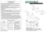
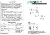
INSTALLATION PROCEDURE
1.Drill holes in FINISHED
DECK per diagram. NOTE:
This kit is intended for
installation up to 2" thick.
4
5 6
2
1
3
1-800-558-8700
Mequon, WI 53092
Design House is a registered
brand of DHI Corp.
TWO HANDLE
ROMAN TUB FAUCET
Models 523449, 523431
silicon sealer
flashlight
faucet supply tubes
basin wrench
Teflon tape
(2) crescent wrenches
Your new Design House faucet will give you years of trouble free performance. Thank you for
choosing our product for your home. Please read all of these instructions carefully before
installing your new faucet.
Helpful tools to install this faucet:
IMPORTANT POINTS
When installing your new faucet, hand tighten the connector nuts, then use one wrench to
anchor the fitting and a second wrench to tighten the nut one additional turn. Connections that
are too tight will reduce the integrity of the system.
Wrap threaded connections (except aerator thread in spout or where o-ring or rubber sealant
are present) with Teflon tape available from your local hardware or plumbing supply store.
Always wrap in a clockwise direction.
SAFETY TIPS
ALWAYS protect your eyes with safety glasses.
CONSUMER PROTECTION WARNING
Under the Safe Drinking Water Act, the U.S. Environmental Protection Agency restricts the
amount of lead used in brass and solder. Your new faucet is made in strict compliance with
all government standards. The materials used in the manufacture of this faucet are of industry
standard quality and are similar to other plumbing products having brass fittings.
To reduce the amount of lead in your drinking water, allow the water to run for a moment before
filling your glass and remember to always use cold water for drinking purposes.
Your new Design House faucet is designed to give you years of trouble free performance. Keep it looking
new by cleaning it periodically with a soft cloth. Avoid abrasive cleaners, steel wool and harsh chemicals
that will dull the finish and void your warranty
Brass finishes are polished, then protected with a lacquer coating to help prevent tarnishing. Clean these
surfaces only with a damp, soft cloth.
INSTALLATION PROCEDURE
MAINTENANCE
5D
5C
5B
5A
6B
6D
6C
6A
7.Screw the flange (7A) to
the flange seat (7B). Place
the handle assembly (7C)
to the cartridge stem (7D)
and secure with screw
(7E). Insert the index (7F).
7E
7C
7A
Index
Screw
Handle
Handle Connector
Handle Seat
Bonnet
Cartridge
Flange
Valve Body
Spout Body
7B
7D
7F
2A
2B
2C
2D
2E
2F
10
11
4.Unscrew the set screw (4A),
then remove the spout
assembly (4B) from spout
body (4C).
4A
4B
4C
8B
/


