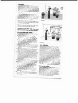
Condair ML RO Installation guide

Type
Installation guide
Humidication and Evaporative Cooling
Reverse Osmosis system
ML RO 100-1500 series.
INSTALLATION AND
OPERATION MANUAL
MLRO GB 062017
Thank you for choosing Condair
Installation date (MM/DD/YYYY):
Commissioning date (MM/DD/YYYY):
Site:
Model:
Serial number:
Manufacturer
Condair A/S
Parallelvej 2, DK-8680 Ry
phone +45 8788 2100
condair.dk@condair.com, www.condair.dk
Proprietary Notice
This document and the information disclosed herein are proprietary data of Condair A/S. Neither this document, nor
the information contained herein shall be reproduced, used, or disclosed to others without the written authorization
of Condair A/S, except to the extent required for installation or maintenance of recipient's equipment.
Liability Notice
Condair A/S does not accept any liability due to incorrect installation or operation of the equipment or due to the
use of parts/components/equipment that are not authorized by Condair A/S.
Copyright Notice
Copyright 2015, Condair A/S All rights reserved.
Technical modications reserved
3Table of content
Table of content
1
5
1.1 5
1.2 6
1.3 6
1.3.1 7
1.4 8
1.4.1 9
1.5 9
1.6 9
1.7 9
1.8 10
1.8.1 10
2 11
2.1 11
2.2 12
2.3 13
2.3.1 14
2.4 15
2.4.1 16
2.5 17
2.5.1 18
2.6 19
2.6.1 20
2.7 21
2.7.1 22
2.7.2 23
2.7.3 24
2.8 25
2.9 26
2.10 26
3 27
3.1 27
3.1.1 27
3.1.2 27
3.1.3 28
3.1.4 28
3.2 29
3.2.1 30
3.2.2 30
3.3
General information
Foreword
Health and safety
Hygeine
Guidelines to ensure your system stays clean and prevent the growth of Legionella
Intended use
Ensure safe operation
Warranty
Delivery and storage
Correct method of lifting
Disposal
Disinfection
Product overview
ML RO description
Inlet water quality requirements
MLRO 100 - Piping Diagram
MLRO 100 - Part specication
MLRO 300 - Piping Diagram
MLRO 300 - Part specication
MLRO 500 - Piping Diagram
MLRO 500 - Part specication
MLRO 800 - Piping Diagram
MLRO 800 - Part specication
MLRO 1000 - Piping Diagram
MLRO 1000 - Part specication
MLRO 1500 - Piping Diagram
MLRO 1500 - Part specication
Optional equipment for ML RO
Rating and markings
Electrical schematic diagrams
Installation
Important notes on installation
Qualication of personnel
Safety
Tools needed for installation work
Please observe the following on positioning and installation
Positioning the pump station
Drain
Water connection
Electrical installation
31
4 Table of content
4 Installation 32
4.1 Tools and materials for commissioning work 32
4.2 Inlet lter 33
4.3 Insert RO membrane 34
4.4 RO tank breating lter 35
4.5 Basic set-up of the system 35
4.6 Option setup 38
4.7 RO membrane ush and startup 41
4.8 Adjusting the reverse osmosis 42
4.8.1 Water quality 43
4.8.2 Adjustment of outlet amount 44
4.8.3 Adjustment of permate amount 45
5 Operation 46
5.2 Overview cabinet 46
5.1 Equipment protection 46
5.3 Alarm message 47
5.4 Controller menu 49
5.4.1 Start page - basic settings 49
5.4.2 Operation and menu page 50
5.4.3 Alarm messages 51
5.4.4 Pump setup 51
5.4.5 Pages for the EC monitoring and regulation (option) 52
5.5 Weekly inspection 53
6 Weekly inspection 54
6.1 Important notes on maintenance 54
6.2 Maintenance work 54
6.3 Preventive spare parts chart 56
6.4 Weekly check list 57
6.5 Troubleshooting 58
6.5.1 Qualication of personnel 58
6.5.2 Safety 58
6.5.3 Resetting the error indication 60
6.5.4 Resetting the error indication 61
7 Product data 62
8 Declaration of conformity 64
9 Appendices 65
Table of content
5General information
DANGER!
Danger of electric shock!
Installations and electrical connection must only be done by trained technicians and according to local
standards.
High voltages, danger of electric shock! Touching live parts may cause severe injury or death.
WARNING!
Do not retighten/unscrew hoses while the system is pressurised!
The system start-up must be carried out or monitored by persons approved and trained by Condair.
Errors in the start-up phase may ultimately result in illness, injury and death of humans.
CAUTION!
Do not use oil, grease, glue, Teon, silicon, O-ring lubrication, etc. when assembling pipes or hose
connections.
All of the above products can act as food for bacteria and are thus pose health risks.
Only approved lubricant: Dish soap.
Wash your hands before or wear clean gloves while assembling parts in direct contact with water.
Keep dust covers on pipes and hoses until just before assembly.
Do not fasten the pump station or hoses/pipes to vibrating installations
When tting water lters, RO membranes, hoses and other components in direct contact with water
please, wear sterile gloves or touch only the packing paper to keep the lter bacteria-free.
Remember to wash your hands!
This manual has been written to ensure the safe use, performance and longevity of the equipment,
and is intended for use by engineers and properly trained technical personnel. Please read this manual
thoroughly before specifying, designing or installing an ML-System from Condair A/S. Keep for future
reference.
As our policy is one of continuous research and development, we reserve the right to amend, without
notice, the specications provided in this document. Condair A/S does not guarantee nor accept liability
for the accuracy of information in this document.
1 General information
1.1 Foreword
6 General information
WARNING!
The ML RO must be installed, operated and maintained in accordance with this manual. Failure to do
so could result in contamination that might cause Legionnaires’ disease, which can be fatal.
WARNING!
To prevent water stagnation and microbial contamination, the ML RO power supply should be left
switched on. If the system is switched off for more than 48 hours, the pipework and system must be
disinfected as per the instructions, and a full risk assessment must be undertaken to ensure safe
operation.
Installation, maintenance, repair work or decommissioning should only be carried out by appropriately
qualied and properly trained technical personnel. The users are responsible for ensuring their suit-
ability. The customer is responsible for ensuring that the installation of the equipment complies with all
local regulations.
Any risks or hazards relating to the system, including during installation and maintenance, should be
identied by a competent health and safety representative who is responsible for introducing effective
control measures.
All ideograms, signs and markings applied to the unit must be observed and kept in a readable state.
Please observe the local health and safety executive’s technical guidance on the control of Legionellosis
in water systems.
The user is responsible for ensuring that the water system complies with local regulations, bylaws and
guidelines (such as the HSE ACoP L8, VDI 6022, ISO 22000, HACCP or equivalent). If inadequately
maintained, the RO-system, can support the growth of microorganisms, including the bacterium that
causes Legionnaires’ disease.
The ML RO is produced according to the ISO 22000 standards, which means that we have considered
all aspects of this equipment to reduce the risk of Legionnaires’ disease and other similar conditions.
However, the user is responsible for ensuring that the installation, operation and maintenance work on
the equipment is performed in a manner ensuring that the system stays clean!
Any risks or hazards relating to the system, including during installation and maintenance, should be
identied by a competent health and safety representative who is responsible for introducing effective
control measures.
1.2 Health and safety
1.3 Hygeine
7General information
Carry out a risk assessment of the water system using a competent person, and implement an
appropriate monitoring and control programme.
Initiate procedures for checking the UV system, cleaning tanks, changing lters, disinfection etc.
The ML RO must be connected to a clean, potable mains water supply.
Enter into a service contract that suits your company
Stop the system if polluted drinking water is found in your area.
Avoid water temperatures between 25°C and 45°C that favour the growth of Legionella.
Do not stop the system unless it is faulty or leaking (avoid water stagnation)
Refrain from closing nozzles or sections, unless there is leakage or a fault (avoid water stagnation)
Disinfect the high-pressure system at least once a year and after every maintenance or repair.
Always carry out a complete system disinfection if it has been turned off for more than 48 hours
Have water samples taken and tested for harmful bacteria at least once a year.
Conduct follow-up measurements until the system is clean if bacteria have been detected in the
system.
The Condair service team can help. Condair has expert technicians who can provide:
Bacteriological troubleshooting on site *
Cleaning and disinfecting
Preventive maintenance
Repair and fault nding
Training and guidance
*Condair uses a quick method for measuring bacterial activity in the water: the approved and patented
BactiQuant. Once the water sample has been taken, we can read the bacteriological quality of the water
within 30 minutes, and disinfect the system if necessary.
Condair follows the guidelines in VDI 6022 for CFU counts in humidiers. The CFU count in the humidi-
cation water must not exceed 150 CFU/ml, corresponding to a maximum BQ value of 40.
Please contact your local Condair representative for further information about our services.
1.3.1 Guidelines to ensure your system stays clean and prevent the growth of Legionella
8 General information
WARNING!
Risk of electric shock! A person may come in contact with live parts when the pump station/control
unit is open. Touching live parts may cause severe injury or death.
Prevention: Before carrying out any work on the system, disconnect power and water supply.
WARNING!
Poorly maintained RO systems may be hazardous.
Prevention: read, understand and follow maintenance guidelines to ensure your system stays safe.
WARNING!
Water produced from a RO system is very aggressive and can cause metals to corrode quickly. The
RO system should always be connected to piping / equipment suitable for handling RO water.
The ML RO is designed for producing RO water and delivering this from it’s holding tank at a pressure
of 3 bars. Any other, or further, application is not considered use for the intended purpose. Condair A/S
cannot be made liable for any damage or injury attributable to inattentive, inappropriate, negligent or
incorrect operation of the equipment, whether or not caused deliberately.
Operation of the equipment in the intended manner requires that all the information in this installation
and operation manual be observed (in particular the safety instructions).
Potential danger related to the ML RO.
1.4 Intended use
9General information
If it is suspected that safe operation has been compromised, the ML RO should immediately be shut
down and secured against accidental power-up.
Shut down the ML RO if:
ML RO components are damaged, worn or very soiled.
The ML RO does not work correctly.
Joints, pipes or hoses are leaking.
1.4.1 Ensure safe operation
1.5
1.6
1.7
No modications must be made on the ML RO without the manufacturer's consent. All persons working
with the ML RO must report any alterations made to the ML RO to the owner immediately.
Use only original accessories and spare parts available from your Condair representative.
Warrant
y
ML RO parts are covered by a two-year warranty from the invoice date with the exception of the replace-
ment parts listed in the routine maintenance section. Failure to observe the manufacturer's installation
and maintenance recommendations and instructions will invalidate the warranty. Condair A/S cannot
be made liable for damage or injury attributable to failure to observe the manufacturer's installation and
maintenance recommendations and instructions
Delivery and storage
To ensure consistent quality, each ML RO is tested and preserved before leaving the factory. If put into
storage prior to use, the ML RO must be covered and protected from physical damage, dust, frost and rain.
It is recommended that the ML RO be kept in its transit packaging for as long as possible prior to installation.
Inspection
Upon receipt, remove the transit packaging and inspect the unit to ensure that no damage has occurred
during transit. Any visible damage must be reported to your Condair distributor immediately. If the unit
is put into storage, the packaging should be replaced.
Correct method of lifting
Lifting or handling must only be carried out by trained and qualied personnel. Ensure that the lifting
operation has been properly planned and risk-assessed, and that all equipment has been checked by
a skilled and competent health and safety representative.
The customer is responsible for ensuring that operators are trained in handling heavy goods, and to
enforce the relevant lifting regulations. Refer to the weights and measures section for system weight.
10 General information
You must observe local laws and regulations when disposing of your ML RO at the end of its working
life. The pumps and piping are constructed from stainless steel which may be fully recycled.
1.8.1 Disinfection
Depending on the system hygiene, it is advised that preventative disinfection uid is added to the ML
RO water tank at an appropriate frequency, but at least once a year.
Condair A/S recommends adding the disinfection uid SANOSIL S010 AG 5% (our code: 155404000)
to the tank, desired concentration 0.1%. SANOSIL is safe, non-toxic and eco-friendly which provides a
prophylactic, disinfection dose and is effective against all types of microorganisms, including Legionella
and E.coli.
Please read the Maintenance section for more information on disinfection.
If you are in any doubt about the suitability of water quality, please contact your Condair distributor who
will be happy to support you.
1.8 Disposal
11Product overview
Reverse osmosis system (from now on called RO) with reservoir tank for removal (>95%) of salts and
minerals in tap water.
The systems are developed by Condair A/S with focus on reliable and hygienically correct solutions. The
system uses a membrane separation process in which water molecules can pass through the membrane,
while the majority of salts and minerals are retained and thereafter ushed out the drain.
The system components are tted on an ‘easy-to-place’ base frame. The ML RO 100 and 300 has 55/15
liter/gal holding tank for the produced RO water, mounted directly on the pump frame. The holding tanks
of ML RO 500, 800, 1000 and 1500 are placed on separate frames (200/53, 500/132, 1000/264 liter/gal).
There are two or three pumps on the pump frame: The RO pump(s) which pumps the raw water through
the RO membrane at a pressure of 8-12 bar and into the RO water tank. RO water transfer pump, which
delivers pressurized RO water to the consumer at 3,5 bar.
All components exposed to water are made of corrosion-resistant material. All hoses are steel-reinforced
and drinking water-approved.
Both the transfer and RO pump are directly mounted on their electric motors. Power is supplied to the
3-phase asynchronous motors via a magnet-operated protective motor switch.
The transfer pump is protected against dry running by the level sensor in the RO tank that stops the
system if the tank is empty.
A pressure switch just after the inlet lter protects the RO pump from dry running.
The control unit consists of a touch display and a PLC mounted in the IP 65-rated electrical cabinet.
From the touch screen, the operator can change settings, adjust alarm limits and view hour counters,
logged alarms, etc.
The ML RO’s are delivered assembled, tested, and ready to use.
2 Product overview
2.1 ML RO description
12 Product overview
The quality of the water being used in the ML RO system should be checked prior to system commission-
ing. Condair A/S recommends that the ML RO system is connected to a clean, potable (drinking water
quality) mains water supply. If the inlet water does not meet the quality specied in the preconditions
table, it may be necessary to install additional water treatment.
Preconditions:
ML RO 100 consumption and inlet pressure 200 L/h @ 2.5-7 bar (dynamic)
ML RO 300 consumption and inlet pressure 600 L/h @ 2.5-7 bar (dynamic)
ML RO 500 consumption and inlet pressure 700 L/h @ 2.5-7 bar (dynamic)
ML RO 800 consumption and inlet pressure 1100 L/h @ 2.5-7 bar (dynamic)
ML RO 1000 consumption and inlet pressure 1400 L/h @ 2.5-7 bar (dynamic)
ML RO 1500 consumption and inlet pressure 2100 L/h @ 2.5-7 bar (dynamic)
Connection inlet: G 3/4“
Connection outlet: G 3/4“
Water supply: Potable water quality
Hardness: ML RO 100, 300: max 20 °dH
Hardness: ML RO 500, 800, 1000, 1500: max 1 °dH
Conductivity: 120-1000 µS/cm
Free chlorine: 0,1 mg/L
TDS: max 625 mg/L
Silt index: max 3.0
KMnO4: max 10 mg/L
Fe: max 0.2 mg/L
Mn: max 0.05 mg/L
NTU: max 1.0
Temperature of inlet water:
max 40°C
Recommended max 15°C (hygienic precaution)
2.2 Inlet water quality requirements
13Product overview
F1
MV1
G3
RO1
UV
C1
D
MV3 MV2
V4
EC
M1
V3
K1
P1
L1
PS1
MV6
V5
V1
K4
M2
P2
C2
PS2
V8
G4
V9
F3
MV7
K2
F6
EC2
EC4
F4
F5
EC1
K3
Option EC REG 8
C3
P3
CIP Option
F2
US
G2
PO
WM
3/4"
3/4"
R3
CO2
MV8
Option CO2
Not supplied
by CC-Ry
V2
V10
ML RO 100-300
FD041-07
28.04.2017
LAA/KK
Piping & Instrumentation Diagram
2.3 MLRO 100 - Piping Diagram
14 Product overview
PART SPECIFICATION
C1 Permeate tank, 55 L
C2 Hydrophore, 8 L
D Drain pipe, 3/4" RG
F1 Filter 20", 5 µm
F2 Sterile breathing filter 0,2 µm
F3 Suction filter
G2
Pressure gauge, inlet pressure RO pump 0-10 bars
G3 Pressure gauge, RO pump pressure 0-10 bars
G4 Pressure gauge, 0-10 bars
K1 Check valve 16 bar, back pressure max 0,1 bar
K4 Check valve
M1/P1 RO pump
M2/P2 Feed pump
MV1 ON/OFF valve, 0-10 bars
MV2 Valve for flushing at start-up
MV3 Valve for membrane flushing
MV7 ON/OFF valve
PS1 Pressure switch, pre-adjusted to 0.5 bar
PS2 Pressure switch, type CS
RO1 RO membrane in stainless steel housing
US Ultra sound level sensor
V1 Test water tap 1/8“
V2 Ball valve for pressure adjustment
V3 Needle valve for concentrate outlet adjustment
V4 Test water tap 1/8“
V8 Ball valve
V9 Ball valve
V10 Ball valve
WM Water meter for permeate
CO
2 option
CO2 (Option) CO
2 container
MV8 (Option) Valve for CO
2
R3 (Option) CO2 pressure regulator
CIP option
C3 (Option) CIP container, 1 L plastic bottle
P3 (Option) CIP pump
EC REG 8 option
EC1 (Option) Conductivity sensor
EC2 (Option) Conductivity sensor
EC4 (Option) Conductivity sensor
F4 (Option) Filter, 5" 5 µ
F5 (Option) Mixbed, ion exchange bottle (Acquired locally)
F6 (Option) Mixbed, ion exchange bottle (Acquired locally)
K2 (Option) Check valve
K3 (Option) Check valve
EC option
EC (Option) Conductivity sensor
PO option
PO (Option) Pulse output for water meter
Misc. options
MV6 (Option) Valve for raw water mix, 0-10 bars
UV (Option) UV system
V5 (Option) Needle valve
ML RO 100-300
FD041GB-07
28.04.2017
LAA/KK
Part specification
Piping & Instrumentation Diagram
2.3.1 MLRO 100 - Part specication
15Product overview
F1
MV1
G3
RO1
UV
C1
D
MV3 MV2
V4
EC
M1
V3
K1
P1
L1
PS1
MV6
V5
V1
K4
M2
P2
C2
PS2
V8
G4
V9
F3
MV7
K2
F6
EC2
EC4
F4
F5
EC1
K3
Option EC REG 8
C3
P3
CIP Option
F2
US
G2
PO
WM
3/4"
3/4"
R3
CO2
MV8
Option CO2
Not supplied
by CC-Ry
V2
V10
ML RO 100-300
FD041-07
28.04.2017
LAA/KK
Piping & Instrumentation Diagram
2.4 MLRO 300 - Piping Diagram
16 Product overview
PART SPECIFICATION
C1 Permeate tank, 55 L
C2 Hydrophore, 8 L
D Drain pipe, 3/4" RG
F1 Filter 20", 5 µm
F2 Sterile breathing filter 0,2 µm
F3 Suction filter
G2 Pressure gauge, inlet pressure RO pump 0-10 bars
G3 Pressure gauge, RO pump pressure 0-10 bars
G4 Pressure gauge, 0-10 bars
K1 Check valve 16 bar, back pressure max 0,1 bar
K4 Check valve
M1/P1 RO pump
M2/P2 Feed pump
MV1 ON/OFF valve, 0-10 bars
MV2 Valve for flushing at start-up
MV3 Valve for membrane flushing
MV7 ON/OFF valve
PS1 Pressure switch, pre-adjusted to 0.5 bar
PS2 Pressure switch, type CS
RO1 RO membrane in stainless steel housing
US Ultra sound level sensor
V1 Test water tap 1/8“
V2 Ball valve for pressure adjustment
V3 Needle valve for concentrate outlet adjustment
V4 Test water tap 1/8“
V8 Ball valve
V9 Ball valve
V10 Ball valve
WM Water meter for permeate
CO
2
option
CO2 (Option) CO
2
container
MV8 (Option) Valve for CO
2
R3 (Option) CO
2
pressure regulator
CIP option
C3 (Option) CIP container, 1 L plastic bottle
P3 (Option) CIP pump
EC REG 8 option
EC1 (Option) Conductivity sensor
EC2 (Option) Conductivity sensor
EC4 (Option) Conductivity sensor
F4 (Option) Filter, 5" 5 µ
F5 (Option) Mixbed, ion exchange bottle (Acquired locally)
F6 (Option) Mixbed, ion exchange bottle (Acquired locally)
K2 (Option) Check valve
K3 (Option) Check valve
EC option
EC (Option) Conductivity sensor
PO option
PO (Option) Pulse output for water meter
Misc. options
MV6 (Option) Valve for raw water mix, 0-10 bars
UV (Option) UV system
V5 (Option) Needle valve
ML RO 100-300
FD041GB-07
28.04.2017
LAA/KK
Part specification
Piping & Instrumentation Diagram
2.4.1 MLRO 300 - Part specication
17Product overview
F1
MV1 G3
RO1
D
MV3 MV2
M1
V3
V2
K1
P1
WM
PS1
MV6 V5
V1
MV7
K2
F6
EC2
EC4
F4
F5
EC1
K3
Option EC REG 8
G2
RO2
F2
US
C3
P4
CIP Option
C1
K4
M2
PS2
P2
C2
V4
G4
V6
D
F3
UV
EC
PO
3/4"
3/4"
R3
CO2
MV8
Option CO2
Not supplied
by CC-Ry
ML RO 500
FD044-04
16.06.2016
LAA/KK
Piping & Instrumentation Diagram
2.5 MLRO 500 - Piping Diagram
18 Product overview
PART SPECIFICATION
C Permeate tank, 200 L, external on stand
C2 Hydrophore, flowthrough, 8 L
D Drain pipe, 3/4" RG
F1 Filter 20", 5 μm
F2 Sterile breathing filter 0,2 μm
F3 Suction filter
G2 Pressure gauge, inlet pressure RO pump 0-10 bars
G3 Pressure gauge, RO pump pressure 0-10 bars
G4 Pressure gauge
K1 Check valve
K4 Check valve
M1/P1 RO pump
M2/P2 Feed pump
MV1 ON/OFF valve, 0-10 bars, 3/4"
MV2 Valve for flushing at start-up
MV3 Valve for membrane flushing
MV7 ON/OFF valve
P2 PAHT high pressure pump 70 bars
PS1+2 Pressure switch, pre-adjusted to 0.5 bar
RO1-2 RO membrane in stainless steel housing
US Ultra sound level sensor
V1 Test water tap 1/8“
V2 Valve for pressure adjustment
V3 Needle valve for concentrate outlet adjustment
V4 Ball valve
V6 Drain valve
WM Water meter for permeate
CO
2 option
CO2 (Option) CO
2 container
MV8 (Option) Valve for CO
2
R3 (Option) CO2 pressure regulator
CIP option
C3 (Option) CIP container, 1 L plastic bottle
P3 (Option) CIP pump
EC REG 8 option
EC1 (Option) Conductivity sensor
EC2 (Option) Conductivity sensor
EC4 (Option) Conductivity sensor
F4 (Option) Filter, 5" 5 μ
F5 (Option) Mixbed, ion exchange bottle (Acquired locally)
F6 (Option) Mixbed, ion exchange bottle (Acquired locally)
K2 (Option) Check valve
K3 (Option) Check valve
EC option
EC (Option) Conductivity sensor
PO option
PO (Option) Pulse output for water meter
Misc. options
MV6 (Option) Valve for raw water mix, 0-10 bars
UV (Option) UV system
V5 (Option) Needle valve
ML RO 500
FD044GB-04 16.06.2016 LAA/KK
Part specification
Piping & Instrumentation Diagram
2.5.1 MLRO 500 - Part specication
19Product overview
F1
MV1
G3
RO1
V3
UV
F2
C1
D
MV3 MV2
G2
EC
V1
RO2
K1
M1
P1
PS1
MV7
K2
F6
EC2
EC4
F4
F5
EC1
K3
RO3
US
C3
P3
Option EC REG 8
CIP Option
K4
M2
PS2
P2
C2
V9
G4
V8
D
F3
MV6
V5
PO
WM
3/4"
3/4"
R3
CO2
MV8
Option CO2
Not supplied
by CC-Ry
V2
ML RO 800
FD045-06
04.01.2017
LAA/KK
Piping & Instrumentation Diagram
2.6 MLRO 800 - Piping Diagram
20 Product overview
PART SPECIFICATION
C1 Permeate tank, 500 L external on stand, black plastic
C2 Hydrophore, flowthrough, 8 L
D Drain pipe, 3/4" RG
F1 Filter 20", 5 µm
F2 Sterile breathing filter 0,2 µm
F3 Suction filter
G2 Pressure gauge, inlet pressure RO pump 0-10 bars
G3 Pressure gauge, RO pump pressure 0-10 bars
G4 Pressure gauge, 0-10 bars
K1 Check valve 16 bar, back pressure max 0,1 bar
K4 Check valve
M1/P1 RO pump
M2/P2 Feed pump
MV1 ON/OFF valve, 0-10 bars
MV2 Valve for flushing at start-up
MV3 Valve for membrane flushing
MV7 ON/OFF valve
PS1 Pressure switch, pre-adjusted to 0.5 bar
PS2 Pressure switch, type CS
RO1-3 RO membrane in stainless steel housing
US Ultra sound level sensor
V1 Test water tap 1/8“
V2 Ball valve for pressure adjustment
V3 Needle valve for concentrate outlet adjustment
V8 Ball valve
V9 Ball valve
WM Water meter for permeate
CO
2
option
CO2 (Option) CO
2
container
MV8 (Option) Valve for CO
2
R3 (Option) CO
2
pressure regulator
CIP option
C3 (Option) CIP container, 1 L plastic bottle
P3 (Option) CIP pump
EC REG 8 option
EC1 (Option) Conductivity sensor
EC2 (Option) Conductivity sensor
EC4 (Option) Conductivity sensor
F4 (Option) Filter, 5" 5 µ
F5 (Option) Mixbed, ion exchange bottle (Acquired locally)
F6 (Option) Mixbed, ion exchange bottle (Acquired locally)
K2 (Option) Check valve
K3 (Option) Check valve
EC option
EC (Option) Conductivity sensor
PO option
PO (Option) Pulse output for water meter
Misc. options
MV6 (Option) Valve for raw water mix, 0-10 bars
UV (Option) UV system
V5 (Option) Needle valve
ML RO 800
FD045GB-06
04.01.2017
LAA/KK
Parts list
Piping & Instrumentation Diagram
2.6.1 MLRO 800 - Part specication
  • Page 1 1
  • Page 2 2
  • Page 3 3
  • Page 4 4
  • Page 5 5
  • Page 6 6
  • Page 7 7
  • Page 8 8
  • Page 9 9
  • Page 10 10
  • Page 11 11
  • Page 12 12
  • Page 13 13
  • Page 14 14
  • Page 15 15
  • Page 16 16
  • Page 17 17
  • Page 18 18
  • Page 19 19
  • Page 20 20
  • Page 21 21
  • Page 22 22
  • Page 23 23
  • Page 24 24
  • Page 25 25
  • Page 26 26
  • Page 27 27
  • Page 28 28
  • Page 29 29
  • Page 30 30
  • Page 31 31
  • Page 32 32
  • Page 33 33
  • Page 34 34
  • Page 35 35
  • Page 36 36
  • Page 37 37
  • Page 38 38
  • Page 39 39
  • Page 40 40
  • Page 41 41
  • Page 42 42
  • Page 43 43
  • Page 44 44
  • Page 45 45
  • Page 46 46
  • Page 47 47
  • Page 48 48
  • Page 49 49
  • Page 50 50
  • Page 51 51
  • Page 52 52
  • Page 53 53
  • Page 54 54
  • Page 55 55
  • Page 56 56
  • Page 57 57
  • Page 58 58
  • Page 59 59
  • Page 60 60
  • Page 61 61
  • Page 62 62
  • Page 63 63
  • Page 64 64
  • Page 65 65
  • Page 66 66
  • Page 67 67
  • Page 68 68
  • Page 69 69
  • Page 70 70
  • Page 71 71
  • Page 72 72

Condair ML RO Installation guide

Type
Installation guide

Ask a question and I''ll find the answer in the document

Finding information in a document is now easier with AI