Dell W-AP134/135 Quick start guide

Category
WLAN access points
Type
Quick start guide

Dell W-AP134/135 access points are high-performance wireless devices designed for businesses. They support the latest IEEE 802.11n standard, offering fast and reliable wireless connectivity. With MIMO technology, they can handle multiple data streams simultaneously, improving overall network efficiency. These versatile access points can operate in various modes, including wireless access point, wireless air monitor, and can be centrally managed and configured through a Dell Controller. They also support Power over Ethernet (PoE), allowing for easy installation and power supply.

Dell W-AP134/135 access points are high-performance wireless devices designed for businesses. They support the latest IEEE 802.11n standard, offering fast and reliable wireless connectivity. With MIMO technology, they can handle multiple data streams simultaneously, improving overall network efficiency. These versatile access points can operate in various modes, including wireless access point, wireless air monitor, and can be centrally managed and configured through a Dell Controller. They also support Power over Ethernet (PoE), allowing for easy installation and power supply.

Dell PowerConnect W-AP130 Series Access Point
Installation Guide
0510972-01 | June 2011 1
The Dell W-AP130 Series of wireless access points support the IEEE 802.11n standard for high-performance
WLAN. These access points use MIMO (Multiple-in, Multiple-out) technology and support existing
802.11a/b/g/n wireless services. The W-AP130 Series access points work only in conjunction with a Dell
Controller.
The Dell W-AP130 Series access points provide the following capabilities:
Wireless transceiver
Protocol-independent networking functionality
IEEE 802.11a/b/g/n operation as a wireless access point
IEEE 802.11a/b/g/n operation as a wireless air monitor
Compatibility with IEEE 802.3at PoE
Central management configuration and upgrades through a Dell Controller
Minimum Software Requirements
The W-AP130 Series access point requires ArubaOS 6.1.1 or later.
Package Contents
W-AP130 Series access point
Installation guide (this document)
9/16” Ceiling Rail Adapter
15/16” Ceiling Rail Adapter
NOTE: Inform your supplier if there are any incorrect, missing, or damaged parts. If possible, retain the carton, including the
original packing materials. Use these materials to repack and return the unit to the supplier if needed.
NOTE: Additional mounting kits for use with the W-AP130 Series access points are sold separately. Contact your Dell sales
representative for details.
2 Dell PowerConnect W-AP130 Series Access Point | Installation Guide
Device Overview
Figure 1 W-AP130 Series Access Points (W-AP134 Shown)
LEDs
The W-AP130 Series access point is equipped with five LEDs that indicate the status of various components of
the device.
PWR: Indicates the whether or not the W-AP130 Series is powered on and its status.
ENET 0: Indicates the status and activity of Ethernet port 0
ENET 1: Indicates the status and activity of Ethernet port 1
11b/g/n: Indicates the status of the 2.4 GHz radio
11a/n: Indicates the status of the 5.0 GHz radio
For more information about the LEDs and their behavior, see Table 3 on page 9.
External Antenna Connectors
The W-AP134 is designed for use with external antennas. The W-AP135 is equipped with internal antennas.
AP-134_003
134
Antenna Connectors (W-AP134 Only)
LED Status Indicators
Dell PowerConnect W-AP130 Series Access Point | Installation Guide 3
Figure 2 W-AP130 Series Rear
Console Port
Use the console port to connect to a terminal for direct local management.
Ethernet Ports
W-AP130 Series is equipped with two10/100/1000Base-T (RJ-45) auto-sensing, MDI/MDX wired-network
connectivity port. These ports support IEEE 802.3at Power over Ethernet (PoE) compliance, accepting 56VDC as
a standard defined Powered Device (PD) from a Power Sourcing Equipment (PSE) such as a PoE midspan
injector, or network infrastructure that supports PoE.
DC Power Socket
If PoE is not available, an optional Dell AP AC-DC adapter kit (sold separately) can be used to power the
W-AP130 Series.
Reset Button
The reset button can be used to return the AP to factory default settings. To reset the AP:
1. Power off the AP.
2. Press and hold the reset button using a small, narrow object, such as a paperclip.
3. Power-on the AP without releasing the reset button. The power LED will flash within 5 seconds.
4. Release the reset button.
The power LED will flash again within 15 seconds indicating that the reset is completed. The AP will now
continue to boot with the factory default settings.
Kensington Lock Slot
The W-AP130 Series is equipped with a Kensington security slot for additional security.
AP-134_002
CONSOLE
ENET 1
ENET 0
Reset Button
DC Power Socket
Kensington Security Slot
4 Dell PowerConnect W-AP130 Series Access Point | Installation Guide
Before You Begin
Pre-Installation Network Requirements
After WLAN planning is complete and the appropriate products and their placement have been determined, the
Dell Controller(s) must be installed and initial setup performed before the Dell Access Points are deployed.
For initial setup of the Controller, refer to the Dell PowerConnect W-Series ArubaOS 6.1 Quick Start Guide for
the software version installed on your controller.
Pre-Installation Checklist
Before installing your W-AP130 Series access point, be sure that you have the following:
For the W-AP134: External antennas as specified in the network deployment plan
CAT5 or better UTP cable of required length
One of the following power sources:
IEEE 802.3at-compliant Power over Ethernet (PoE) source
The POE source can be any power source equipment (PSE) controller or midspan PSE device
Dell 12 VDC AP AC-DC adapter kit (sold separately)
Dell Controller provisioned on the network:
Layer 2/3 network connectivity to your access point
One of the following network services:
Aruba Discovery Protocol (ADP)
DNS server with an “A” record
DHCP Server with vendor-specific options
CAUTION: FCC Statement: Improper termination of access points installed in the United States configured to non-US model
controllers will be in violation of the FCC grant of equipment authorization. Any such willful or intentional violation may result in a
requirement by the FCC for immediate termination of operation and may be subject to forfeiture (47 CFR 1.80).
CAUTION: EU Statement:
Lower power radio LAN product operating in 2.4 GHz and 5 GHz bands. Please refer to the Dell PowerConnect W-Series
ArubaOS 6.1 User Guide for details on restrictions.
Produit réseau local radio basse puissance operant dans la bande fréquence 2.4 GHz et 5 GHz. Merci de vous referrer au Dell
PowerConnect W-Series ArubaOS 6.1 User Guide pour les details des restrictions.
Low Power FunkLAN Produkt, das im 2.4 GHz und im 5 GHz Band arbeitet. Weitere Informationen bezlüglich Einschränkungen
finden Sie im Dell PowerConnect W-Series ArubaOS 6.1 User Guide.
Apparati Radio LAN a bassa Potenza, operanti a 2.4 GHz e 5 GHz. Fare riferimento alla Dell PowerConnect W-Series ArubaOS 6.1
User Guide per avere informazioni detagliate sulle restrizioni.
Dell PowerConnect W-AP130 Series Access Point | Installation Guide 5
Summary of the Setup Process
Successful setup of a W-AP130 Series access point consists of five tasks, which must be performed in this order:
1. Verify pre-installation connectivity.
2. Identify the specific installation location for each AP.
3. Install each AP.
4. Verify post-installation connectivity.
5. Configure each AP.
Verifying Pre-Installation Connectivity
Before you install APs in a network environment, make sure that the APs will be able to locate and connect to the
Controller when powered on.
Specifically, you must verify the following conditions:
When connected to the network, each AP is assigned a valid IP address
APs are able to locate the Controller (Mobility Controller Discovery)
Refer to the Dell PowerConnect W-Series ArubaOS 6.1 Quick Start Guide for instructions on locating and
connecting to the Controller.
Identifying Specific Installation Locations
You can mount the W-AP130 Series access point a ceiling rail (using the included adapter) or on a wall (using the
wall mount adapter, sold separately). Use the AP placement map generated by Dell’s Airwave VisualRF software
application to determine the proper installation location(s). Each location should be as close as possible to the
center of the intended coverage area and should be free from obstructions or obvious sources of interference.
These RF absorbers/reflectors/interference sources will impact RF propagation and should have been accounted
for during the planning phase and adjusted for in RF plan.
Unidentified Known RF Absorbers/Reflectors/Interference Sources
Identifying known RF absorbers, reflectors, and interference sources while in the field during the installation
phase is critical. Make sure that these sources are taken into consideration when you attach an AP to its fixed
location. Examples of sources that degrade RF performance include:
Cement and brick
Objects that contain water
Metal
NOTE: It is important that you verify the items listed under Pre-Installation Checklist before you attempt to set up and install a
W-AP130 Series AP.
CAUTION: Access points are radio transmission devices and as such are subject to governmental regulation. Network
administrators responsible for the configuration and operation of access points must comply with local broadcast regulations.
Specifically, access points must use channel assignments appropriate to the location in which the access point will be used.
NOTE: Dell, in compliance with governmental requirements, has designed the W-AP130 Series access points so that only
authorized network administrators can change the settings. For more information about AP configuration, refer to the Dell
PowerConnect W-Series ArubaOS 6.1 Quick Start Guide and the Dell PowerConnect W-Series ArubaOS 6.1 User Guide.
6 Dell PowerConnect W-AP130 Series Access Point | Installation Guide
Microwave ovens
Wireless phones and headsets
Installing the AP
Using the Ceiling Rail Adapter
The AP130 series ships with two ceiling rail adapters for 9/16” and 15/16” ceiling rails.
1. Pull the necessary cables through a prepared hole in the ceiling tile near where the AP will be placed.
2. Place the adapter against the back of the AP with the adapter at an angle of approximately 30 degrees to the
tabs (see Figure 3).
3. Twist the adapter clockwise until it snaps into place in the tabs (see Figure 3).
Figure 3 Attaching the Ceiling Rail Adapter
4. If necessary, connect the console cable to the console port on the back of the AP.
5. Hold the AP next to the ceiling tile rail with the ceiling tile rail mounting slots at approximately a 30-degree
angle to the ceiling tile rail (see Figure 4). Make sure that any cable slack is above the ceiling tile.
6. Pushing toward the ceiling tile, rotate the AP clockwise until the device clicks into place on the ceiling tile rail.
NOTE: Service to all Dell products should be performed by trained service personnel only.
CAUTION: Make sure the AP fits securely on the ceiling tile rail when hanging the device from the ceiling, because poor
installation could cause it to fall onto people or equipment.
AP-130_001
Dell PowerConnect W-AP130 Series Access Point | Installation Guide 7
Figure 4 Mounting the AP
7. On the W-AP134, install the external antennas according to the manufacturer’s instructions, and connect the
antennas to the antenna interfaces on the AP.
Connecting Required Cables
Install cables in accordance with all applicable local and national regulations and practices.
Ethernet Ports
The RJ45 Ethernet ports (ENET0 and ENET1) support 10/100/1000Base-T auto-sensing MDI/MDX
connections. Use these ports to connect the AP to a twisted pair Ethernet LAN segment or directly to a Dell
Controller. Use a 4- or 8-conductor, Category 5 UTP cable up to 100 m (325 feet) long.
The 10/100/1000 Mbps Ethernet ports are on the bottom of the AP. These ports have RJ-45 female connectors
with the pin-outs shown in Table 1.
Table 1 Ethernet Port Pin-out
Connector Pin
Signal
Name
GE Connection
FE
Connection
PoE
1 BI_DA+ Bi-directional pair A+ RX+ POE negative
2 BI_DA– Bi-directional pair A– RX– POE negative
3 BI_DB+ Bi-directional pair B+ TX+ POE positive
4 BI_DC+ Bi-directional pair C+ Spare pair POE positive
5 BI_DC– Bi-directional pair C– Spare pair POE positive
6 BI_DB– Bi-directional pair B– TX– POE positive
7 BI_DD+ Bi-directional pair D+ Spare pair POE negative
8 BI_DB– Bi-directional pair D– Spare pair POE negative
AP-130_002
1
2
3
4
5
6
7
8
8 Dell PowerConnect W-AP130 Series Access Point | Installation Guide
Serial Console Port
The serial console port allows you to connect the AP to a serial terminal or a laptop for direct local management.
This port is an RJ-45 female connector with the pinouts described in Table 2. Connect this port in one of the
following ways:
Connect it directly to a terminal or terminal server using an Ethernet cable.
Use a modular adapter to convert the RJ-45 (female) connector on the AP to a DB-9 (male) connector, and
connect the adapter to a laptop using an RS-232 cable. Figure 5 illustrates the connector details of the
adapter.
Figure 5 RJ-45 (Female) to DB-9 (Male) Modular Adapter Conversion
Power Connection
The W-AP130 Series has a single 12V DC power jack socket to support powering through an AC-to-DC power
adapter.
Table 2 Console Port Pin-out
Connector Pin Signal Name Function
3 TXD Transmit
4 GND Ground
5 GND Ground
6 RXD Receive
Pins not listed are not connected.
1
2
3
4
5
6
7
8
3
4
5
2
5
63
RJ-45 DB-9
Internal
Connections
TxD
GND
RxD
1
2
3
4
5
6
7
8
TxD
GND
RxD
RJ-45 Female
Pin-Out
Direction
Input
Output
DB-9 Male
Pin-Out
TxD
RxD
Ground
5
4
3
2
1
9
8
7
6
Direction
Input
Output
NOTE: If both POE and DC power are available, the AP uses POE even when there is not enough POE voltage available to power
the AP.
Dell PowerConnect W-AP130 Series Access Point | Installation Guide 9
Verifying Post-Installation Connectivity
The integrated LEDs on the AP can be used at this point to verify that the AP is receiving power and initializing
successfully (see Table 3). Refer to the Dell PowerConnect W-Series ArubaOS 6.1 Quick Start Guide for further
details on verifying post-installation network connectivity.
Table 3 W-AP130 Series LED Behavior
Configuring the W-AP130 Series
AP Provisioning/Reprovisioning
Provisioning parameters are unique to each AP. These local AP parameters are initially configured on the
Controller which are then pushed out to the AP and stored on the AP itself. Dell recommends that provisioning
settings be configured via the ArubaOS WebUI only. Refer to the Dell PowerConnect W-Series ArubaOS 6.1 User
Guide for complete details.
AP Configuration
Configuration parameters are network or controller specific and are configured and stored on the Controller.
Network configuration settings are pushed out to the AP(s) but remain stored on the Controller.
LED Color/State Meaning
PWR Off No power to AP
Green steady Power on, device ready
Green flashing Device booting, not ready
Red steady System failed to initialize
ENET 0
(100/1000 Mbps)
Green/Amber off No link
Green on 1000 Mbps link
Amber on 10/100 Mbps link
Green/amber blinking Link activity
ENET 1
(100/1000 Mbps)
Green/Amber off No Link
Green on 1000 Mbps link
Amber on 10/100 Mbps link
Green/amber blinking Link activity
11A/N Off 5 GHz radio disabled
Amber 5 GHz radio enabled in 11a mode
Green steady 5 GHz radio enabled in 11n mode
Green flashing 5 GHz Air Monitor mode
11B/G/N Off 2.4 GHz radio disabled
Amber 2.4 GHz radio enabled in 11b/g mode
Green steady 2.4 GHz radio enabled in 11n mode
Green flashing 2.4 GHz Air Monitor Mode
10 Dell PowerConnect W-AP130 Series Access Point | Installation Guide
Product Specifications
Mechanical
Dimensions (antenna stowed) (HxWxD):
6.69 inches x 6.69 inches x 1.77 inches
17.0 cm x 17.0 cm x 4.5 cm
Weight: 1.68 lbs/760 g
Shipping Dimensions:
11.22 inches x 9.45 inches x 2.76 inches
28.5 cm x 24.0 cm x 7.0 cm
Temperature:
Operating: 0ºC to 50ºC (32ºF to 122ºF)
Storage: -40ºC to 70ºC (-40ºF to 158ºF)
Relative Humidity: 5% to 95% non-condensing
Mounting:
Ceiling (with included adapter)
Wall (with adapter, sold separately)
Antennas:
6 integrated antenna elements (W-AP135)
3 RP-SMA interfaces for external antennas (W-AP134)
Visual Status Indicators (LEDs): See Table 3
Electrical
Ethernet:
2 x 10/100/1000 Base-T auto-sensing Ethernet RJ-45 Interfaces
MDI/MDX
IEEE 802.3 (10Base-T), IEEE 802.3u (100Base-T). IEEE 802.3ab (1000Base-T)
Power over Ethernet (IEEE 802.3at compliant), 48V DC/350mA (see Table 1 on page 7 for pin
configuration)
Power:
12 VDC power interface, supports powering through an AC-to-DC mains electric power adapter
POE support on Ethernet ports:
– 802.3at-compliant POE sourcing devices
NOTE: Operating temperature range is reduced to 0ºC to 40ºC (32ºF to 104ºF) when this AP is used in conjunction with the Sunny
SYS1357-1812 power adapter.
NOTE: If a power adapter other than the one provided by Dell is used in the US or Canada, it should be cULus (NRTL) Listed, with
an output rated 12VDC, minimum 1.25A, marked “LPS” or “Class 2,” and suitable for plugging into a standard power receptacle in
the US and Canada. For information on approved power adapters, see support.dell.com
Dell PowerConnect W-AP130 Series Access Point | Installation Guide 11
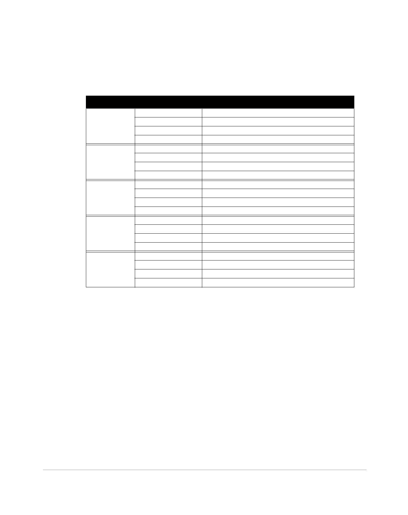
Wireless LAN
Network Standards: IEEE 802.11b, IEEE 802.11g, IEEE 802.11a, and IEEE 802.11n
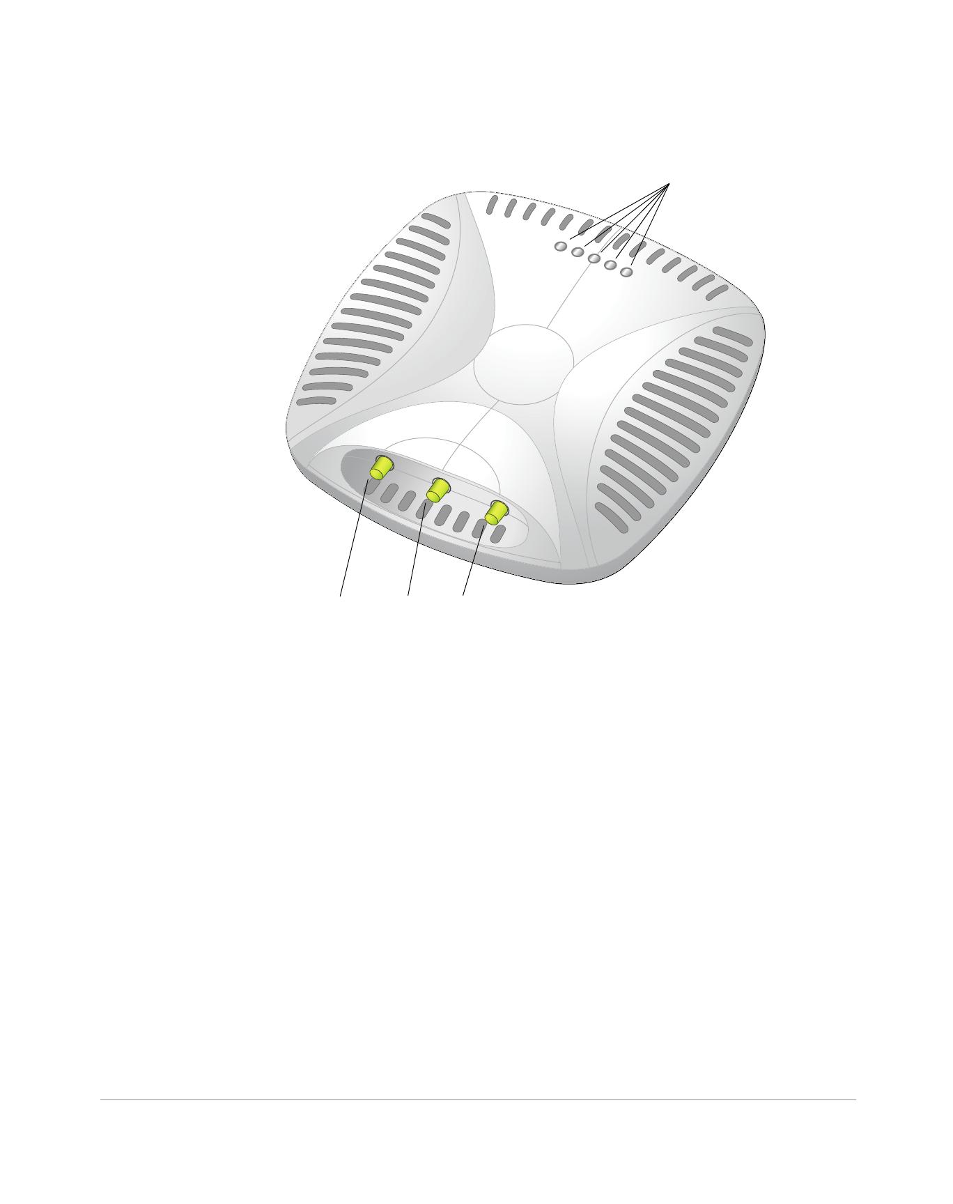
Antenna Type:
Integrated 802.11a/b/g/n omni-directional high-gain antenna
Detachable 802.11a/b/g/n omni-directional high-gain antenna
Antenna Gain (Integrated Antennas):
2.4 – 2.5 GHz (max)
5.180 – 5.825 GHz (max)
Radio Technology:
Orthogonal Frequency Division Multiplexing (OFDM)
Direct Sequence Spread Spectrum (DSSS)
3 x 3 MIMO with up to three spatial streams
Radio Modulation Type:
802.11b - CCK, BPSK, QPSK
802.11a/g/n - CCK, BPSK, QPSK,16-QAM, 64-QAM
Media Access Control: CSMA/CA with ACK
Supported Frequency Bands 2.4GHz:
2.400 ~ 2.4835GHz (Global), channels country specific
Supported Frequency Bands 5GHz:
5.150 ~ 5.250GHz (low band), country-specific
5.250 ~ 5.350GHz (mid band), country-specific
5.470 ~ 5.725GHz (Europe), country-specific
5.725 ~ 5.850GHz GHz (high band), country-specific
Data Rates:
802.11b - 1, 2, 5.5, 11 Mbps per channel
802.11g - 6, 9, 12, 18, 24, 36, 48 and 54 Mbps per channel
802.11a - 6, 9, 12, 18, 24, 36, 48 and 54 Mbps per channel
802.11n - Data rate MCS0 – MCS23 (from 6.5 Mbps to 450 Mbps)
Proper Disposal of Dell Equipment
For the most current information about Global Environmental Compliance and Dell products, see
www.dell.com.
Waste of Electrical and Electronic Equipment
Dell products at end of life are subject to separate collection and treatment in the EU
Member States, Norway, and Switzerland and therefore are marked with the symbol shown at
the left (crossed-out wheelie bin). The treatment applied at end of life of these products in
these countries shall comply with the applicable national laws of countries implementing
Directive 2002/96EC on Waste of Electrical and Electronic Equipment (WEEE).
12 Dell PowerConnect W-AP130 Series Access Point | Installation Guide
European Union RoHS
Dell products also comply with the EU Restriction of Hazardous Substances Directive
2002/95/EC (RoHS). EU RoHS restricts the use of specific hazardous materials in the
manufacture of electrical and electronic equipment. Specifically, restricted materials
under the RoHS Directive are Lead (including Solder used in printed circuit assemblies), Cadmium, Mercury,
Hexavalent Chromium, and Bromine. Some Dell products are subject to the exemptions listed in RoHS Directive
Annex 7 (Lead in solder used in printed circuit assemblies). Products and packaging will be marked with the
“RoHS” label shown at the left indicating conformance to this Directive.
China RoHS
Dell products also comply with China environmental declaration requirements and are labeled
with the “EFUP 10” label shown at the left.
Safety and Regulatory Compliance
Dell provides a multi-language document containing country specific restrictions and additional safety and
regulatory information for all Dell hardware products. The Dell PowerConnect W-Series Safety, Environmental,
and Regulatory Information document is included with this product.
FCC Class B Part 15
This device complies with Part 15 of the Federal Communications Commission (FCC) Rules. Operation is
subject to the following two conditions:
This device may not cause harmful interference.
This device must accept any interference received, including interference that may cause undesired operation.
This equipment has been tested and found to comply with the limits for a Class B digital device, pursuant to Part
15 of the FCC Rules. This equipment generates, uses and can radiate radio frequency energy and, if not installed
and used in accordance with the manufacturer’s instructions, may cause interference harmful to radio
communications.
10
CAUTION: Changes or modifications to this unit not expressly approved by the party responsible for compliance could void the
user’s authority to operate this equipment.
Dell PowerConnect W-AP130 Series Access Point | Installation Guide 13
If this equipment does cause interference, which can be determined by turning the equipment off and on, the
user is encouraged to try to correct the interference by one or more of the following measures:
Reorient or relocate the receiving antenna.
Increase the separation between the equipment and receiver.
Connect the equipment to an outlet on a circuit different from that to which the receiver is connected.
Consult the dealer or an experienced radio or TV technician for help.
Complies with the Class B limits for radio noise emissions as set out in the interference-causing equipment
standard entitled “Digital Apparatus,” ICES-003 of Industry Canada.
Cet apareil numerique de la classe B respecte toutes les exigencies du Reglement sur le materiel brouilleur du
Canada.
EU Regulatory Conformance
This product is CE marked according to the provisions of the R & TTE Directive (99/5/EC) - CE 2280(!). Dell,
hereby declares that this W-AP134 and W-AP135 device models are in compliance with the essential
requirements and other relevant provisions of Directive 1999/5/EC. CE 2280(!)
The Declaration of Conformity made under Directive 1999/5/EC is available for viewing at the following location
in the EU community.
GS Statement
This device is not intended for use in the direct field of view at visual display workplaces. To avoid incommoding
reflexions at visual display workplaces, this device must not be placed in the direct field of view.
CAUTION: RF Radiation Exposure Statement: This equipment complies with FCC RF radiation exposure limits. This equipment
should be installed and operated with a minimum distance of 13.78 inches (35 cm) between the radiator and your body for 2.4
GHz and 5 GHz operations. This transmitter must not be co-located or operating in conjunction with any other antenna or
transmitter. When operated in the 5.15 to 5.25 GHz frequency range, this device is restricted to indoor use to reduce the potential
for harmful interference with co-channel Mobile Satellite Systems.
14 Dell PowerConnect W-AP130 Series Access Point | Installation Guide
This page is intentionally left blank
Dell PowerConnect W-AP130 Series Access Point | Installation Guide 15
This page is intentionally left blank
16 Dell PowerConnect W-AP130 Series Access Point | Installation Guide
Contacting Support
Copyright
© 2011 Aruba Networks, Inc. Aruba Networks trademarks include , Aruba Networks
®
, Aruba Wireless
Networks
®
, the registered Aruba the Mobile Edge Company logo, and Aruba Mobility Management System
®
. Dell™, the
DELL™ logo, and PowerConnect™ are trademarks of Dell Inc.
All rights reserved. Specifications in this manual are subject to change without notice.
Originated in the USA. All other trademarks are the property of their respective owners.
Open Source Code
Certain Aruba products include Open Source software code developed by third parties, including software code subject to the
GNU General Public License (GPL), GNU Lesser General Public License (LGPL), or other Open Source Licenses. The Open
Source code used can be found at this site:
http://www.arubanetworks.com/open_source
Legal Notice
The use of Aruba Networks, Inc. switching platforms and software, by all individuals or corporations, to terminate other
vendors’ VPN client devices constitutes complete acceptance of liability by that individual or corporation for this action and
indemnifies, in full, Aruba Networks, Inc. from any and all legal actions that might be taken against it with respect to
infringement of copyright on behalf of those vendors.
Website Supportain Website
Main Website dell.com
Support Website support.dell.com
Dell Documentation support.dell.com/manuals
  • Page 1 1
  • Page 2 2
  • Page 3 3
  • Page 4 4
  • Page 5 5
  • Page 6 6
  • Page 7 7
  • Page 8 8
  • Page 9 9
  • Page 10 10
  • Page 11 11
  • Page 12 12
  • Page 13 13
  • Page 14 14
  • Page 15 15
  • Page 16 16

Dell W-AP134/135 Quick start guide

Category
WLAN access points
Type
Quick start guide

Dell W-AP134/135 access points are high-performance wireless devices designed for businesses. They support the latest IEEE 802.11n standard, offering fast and reliable wireless connectivity. With MIMO technology, they can handle multiple data streams simultaneously, improving overall network efficiency. These versatile access points can operate in various modes, including wireless access point, wireless air monitor, and can be centrally managed and configured through a Dell Controller. They also support Power over Ethernet (PoE), allowing for easy installation and power supply.

Ask a question and I''ll find the answer in the document

Finding information in a document is now easier with AI