AKH-LD

Newco Enterprises, Inc. AKH-LD Operating instructions

  • Hello! I am an AI chatbot trained to assist you with the Newco Enterprises, Inc. AKH-LD Operating instructions. I’ve already reviewed the document and can help you find the information you need or explain it in simple terms. Just ask your questions, and providing more details will help me assist you more effectively!
6Man Pt No 110326
REV.10-01
N E W C O E N T E R P R I S E S
INSTALLATION and OPERATION MANUAL
For AKH SERIES BREWERS
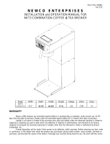
BREWER SPECIFICATIONS
Model
No of
Warmers
Width
Length
Height*
AKH-1 1 8-1/2" 16 3/8" 16 15/16
AKH-2 2 8-1/2" 16 3/8" 18 9/16
AKH-3 3 15-1/2" 16 3/8" 16 15/16
AKH-AP N/A 8-1/2" 16 3/8" 22 15/16
AKH-D N/A 8-1/2" 17 3/8” 21 3/16
AKH-LD N/A 8-1/2" 17 3/8” 21-3/8
AKH-TC N/A 8-1/2" 17 3/8” 17 5/8
AKH-TT N/A 8-1/2" 17 3/8” 16 15/16
AKH-D
AKH-3
2
INSTALLATION INSTRUCTIONS
WARNING: - Read and follow installation instructions before plugging or wiring in machine to electrical circuit.
Warranty will be void if machine is connected to any voltage other than that specified on the name plate.
1) Plug or wire brewer to appropriate voltage circuit
as indicated on serial tag. For (AKH Thermal Model)Turn master
switch, located on rear of brewer, to the ON position.
2) (AKH warmer model), make sure warmer switches are in the OFF position. Place one of the empty decanters on the
warmer located below the brew basket. For (AKH thermo model) pump style airpots, remove the pump stem. Place
the empty dispenser into position below the brewbasket
3) Raise the top evaporation cover and pour ONE decanter (on AKH warmer model) or pitcher (on AKH thermo model)
of water through the pour-in grid into basin.
4) (AKH warmer model), Turn lower warmer/brew switch to the ON or BREW position to start brew cycle.
NOTE: Float assembly will prevent heat pump from activating if water is not present in the basin. This first pot will
be a few ounces short due to some water retention in the system.
5) Machine is now ready to use and will yield a full pot on following brew cycles.
COFFEE PREPARATION PROCEDURES
1) Place the filter into brew basket.
2) Place the appropriate amount of ground coffee into the filter for the volume of coffee to be brewed.
3) Slide the brew basket into holder.
4) For warmer units:
Place empty decanter on warmer located directly under the brew basket
Turn corresponding warmer switch to ON position.
For airpots or other dispensers
Remove any non brew thru lids or pump stems
Place airpot under brew basket.
5) Raise the top evaporation cover and pour ONE decanter(warmer model) or pitcher(therm model) of COLD water
through the pour in grid into the basin. Turn lower warmer / brew switch to the ON position to start the brew cycle.
(AKH warmer model), Brew cycle may be canceled by turning the rocker switch back to the off position.
(AKH thermo model), The brew cycle may be canceled by turning the master switch located on the rear of the
brewer to the off position.
NOTE: Never pour hot water into the brewer. This brewer features a European style brewing system which heats
only the water for coffee when you pour it into the brewer. This type of system does not have a tank to store hot
water. Do not overfill unit by pouring in more than one decanter of water at a time.
6) Hot water will be delivered through the sprayhead. This distributes the hot water evenly over the coffee bed within
the brew basket. The coffee brew will drain from the brew basket into the decanter below.
7) The unique thermal brew system takes a little longer to brew than tank systems, which allow the stored water to
become stale, but the result is better tasting and hotter coffee.
8) (AKH warmer model) TURN OFF WARMERS WHEN NOT IN USE. Red light in switch indicates when warmer is
ON.
9) To clean brew basket simply remove from brew rails and dump filter into waste basket. The brewing process, as
described above, can now be started again.
10 To clean brew basket simply remove from brew rails and dump filter into waste basket. The brewing process, as
described above, can now be started again.
INSTALLATION INSTRUCTIONS (CONTINUED)
3
If unit will not brew, check the following before calling for service:
Is it plugged in?
Is there water in the receiving pan? Water activates the float switch, allowing the unit to brew.
(Warmer model) Is the lower warmer / brew switch in the ON position?
(Thermal model) Is the Master switch located on the rear of the brewer in the on position?
WARRANTY
Newco coffee brewers are warranted against defects in workmanship or materials, under normal use, for 90 days
from the date of purchase. Brewer parts are warranted against defect for 12 months from date of purchase.
Liability in all events is limited to the purchase price paid and liability under the aforesaid warranty is limited to
replacing or repairing any part or parts which are defective in material or workmanship, and returned to our factory,
shipping cost prepaid. No warranty expressed or implied, other than the aforesaid is made or authorized by Newco
Enterprises, Inc.
Prompt disposition will be made if item proves to be defective, within warranty. Before returning any item, write or
call Newco, or the dealer from whom the product was purchased, giving model number, serial number, and date of
purchase, and describe the nature of the defect. If damage was incurred during transit to you, file claim with the carrier.
REPLACEMENT PARTS LIST
Electrical Components Plumbing Components
100085 Switch, ON/OFF Rocker Light 110939 Receiving Pan & Float Assy
110912 Float Switch 102164 Receiving Pan
102421 Heat Pump 1475W, 120V 101954 Silicon Tubing 3/8 ID x 5/8 OD x 13”
102422 Heat Pump 1575W, 120V 102658 Silicon Tubing 3/8 ID x 5/8 OD x 7”
102423 Heat Pump 1275W, 120V
100187 Element, Warmer 100w 120V
102624 Thermostat, HI-Limit, Auto
Labels/Decals Hardware & Miscellaneous
100253 Decal, Caution (Red) 100008 Plate Only, Warmer, Black
100254 Decal, Caution (Hot Surface) 100010 Plate Assy, Warming, Black
110120 Label, Warning (Hot Liquids) 100025 Gasket, Sprayhead
101924 Cover, Receiving Expantion
101925 Spray Head Tube Assy
101956 Screw, 4-40 x 1 1/4, PPHMS
102799 Rail, Brew, R.H.
102800 Rail, Brew, L.H.
110624 Pour-In Cover, Plastic
110625 Pour-in Grid and Cover
201173 Nut, Sprayhead 7/16-20
201210 Sprayhead, Diffuser
COMPONENT REPLACEMENT INSTRUCTIONS
4
CAUTION: DISCONNECT BREWER CORD FROM ELECTRICAL OUTLET BEFORE
REMOVAL OF ANY PANEL OR REPLACEMENT OF ANY COMPONENT!
NOTE: IN CANADA REPAIRS ARE TO BE DONE BY CERTIFIED ELECTRICIAN OR BREWER MUST BE
REINSPECTED TO MAINTAIN APPLICABLE CERTIFICATION
Newco Enterprises, Inc. * 1735 South River Rd. * P.O. Box 852 * St. Charles, MO 63303
/