Bauknecht DSTI 5410 IN/PT User guide

Category
Cooker hoods
Type
User guide

Bauknecht DSTI 5410 IN/PT is a versatile and powerful induction hob that offers a range of features to make cooking easier and more efficient. With its four cooking zones, each with nine power levels, you can cook a variety of dishes simultaneously, from delicate sauces to searing steaks. The hob's touch controls are intuitive and easy to use, allowing you to quickly and precisely adjust the heat settings.

Bauknecht DSTI 5410 IN/PT is a versatile and powerful induction hob that offers a range of features to make cooking easier and more efficient. With its four cooking zones, each with nine power levels, you can cook a variety of dishes simultaneously, from delicate sauces to searing steaks. The hob's touch controls are intuitive and easy to use, allowing you to quickly and precisely adjust the heat settings.

5019 418 33109
INSTALLATION - MONTAGEANLEITUNG
Der Mindestabstand zwischen dem Kochfeld und der unteren Kante der Dunstabzugshaube MUSS
bei Elektroplatten 50 cm und bei Gas- oder kombinierten Herden 65 cm betragen.
Schreiben die Installationsanweisungen des Gaskochfelds einen größeren Abstand vor, ist dieser
natürlich zu beachten.
Beauftragen Sie einen qualifizierten Techniker mit der Installation. Folgen Sie bei der Installation der
Nummerierung (1Ö2Ö3Ö.....).
WARNUNG: Schalten Sie das Stromnetz am Hauptschalter ab, bevor Sie den Anschluss der Abzugshaube
vornehmen.
WARNUNG: Prüfen Sie, ob das Abluftrohr und die Befestigungsmanschetten im Lieferumfang inbegriffen
sind. Andernfalls sind sie separat zu beziehen.
Hinweis: Die mit dem Symbol “(*)” bezeichneten Teile sind Zubehör, das nur mit bestimmten
Modellen oder gar nicht geliefert wird und gesondert erworben werden muss.
WARNUNG: Aufgrund des schweren Gewichtes sind mindestens zwei oder noch mehr Personen zur
Beförderung und Installation der Abzugshaube erforderlich.
INSTALLATION - ASSEMBLY INSTRUCTIONS
The minimum distance between the support surface of the recipients on the cooking device and the
lowest part of the hood MUST NOT BE less than 50 cm in the case of electric cookers and 65 cm for
gas or combination cookers.
If the installation instructions for a gas cooker specify a greater distance, then this distance must be
observed.
Contact a qualified technician for installation. To install, follow steps (Ö2Ö3Ö.....).
WARNING: Disconnect the power at the house main switch before electrically connecting the hood.
WARNING: Check whether the exhaust pipe and clamps are provided. If not, they must be purchased
separately.
Note: Parts marked with the symbol “(*)” are optional accessories supplied only with some models
or parts not supplied, to be purchased separately.
WARNING: Very heavy product; hood handling and installation must be carried out by at least two persons.
INSTALLATION - INSTRUCTIONS DE MONTAGE
La distance minimum entre la surface de support des récipients sur le dispositif de cuisson et la partie
la plus basse de la hotte NE DOIT PAS ÊTRE inférieure à 50 cm pour les cuisinières électriques et à
65 cm pour les cuisinières à gaz ou mixtes.
Si les instructions d’installation du dispositif de cuisson à gaz indiquent une distance supérieure, il est
nécessaire de la respecter.
Faites appel à un technicien qualifié pour l’installation. Pour le montage, suivez la numérotation
(1Ö2Ö3Ö.....).
AVERTISSEMENT : Coupez l’alimentation secteur avant de procéder au branchement électrique de la
hotte.
AVERTISSEMENT : Vérifiez si le conduit d’évacuation et les colliers de fixation sont fournis avec l’appareil.
Dans le cas contraire, il conviendra de les acheter.
Remarque : Les pièces portant le symbole “(*)” sont des accessoires en option fournis seulement avec
certains modèles ou sont des pièces non fournies, à acheter à part.
AVERTISSEMENT : Appareil excessivement lourd ; la manutention et l’installation de la hotte doivent être
effectuées par deux personnes ou plus.
D
GB
F
5019 418 33109
Material supplied
Remove all the components from the packets. Check that all the components are included.
Hood assembled with motor and lamps installed.
Hood reinforcement bracket
Assembly template
Instruction manual
1 - adapter Torx T10
6 plugs 10 x 60
•6 screws 6 x 70
34 screws 3.5 x 9.5
14 screws M4 x 7
IF NL E PGBD GR
5019 418 33109
SAFEGUARDING THE ENVIRONMENT
1. Packing
Packing materials are 100% recyclable and are marked with the
recycling symbol .Comply with the local regulations for
disposal. The packing materials (plastic bags, polystyrene, etc.)
are a potential source of danger and must be kept out of the
reach of children.
2. Product
This appliance is marked in compliance with European Directive
2002/96/EC, Waste Electrical and Electronic Equipment (WEEE).
By ensuring that this appliance is correctly scrapped, the user can
help prevent potentially harmful consequences for the
environment and the health of people.
The symbol on the product or the accompanying
documentation indicates that this product should not be treated
as domestic waste but must be taken to a suitable collection
centre for the recycling of electrical and electronic equipment.
Disposal must be carried out in compliance with local regulations
on waste disposal.
For further information on the treatment, recovery and recycling
of this product, contact the competent local office, the
household waste collection service or the shop where you
purchased the appliance.
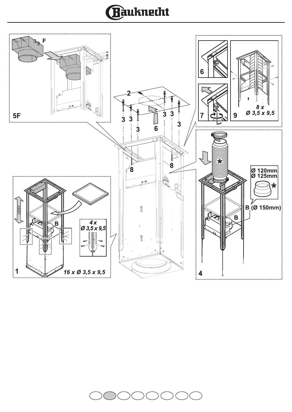
IMPORTANT INSTRUCTIONS FOR
SAFETY
WARNING: To reduce the risk of accidents, electric shock,
injury or damage, when using the hood comply with the basic
precautions, including the following.
1. Always disconnect the hood from the power supply before
carrying out any installation or maintenance operation on the
appliance.
2. Installation must be carried out by a specialised technician, in
compliance with the manufacturer’s instructions and local
safety regulations.
3. Earthing of the appliance is compulsory. (Not possible for
Class II hoods).
4. Never use multisockets and extension leads.
5. The electrical components must no longer be accessible to
the user after installation.
6. Do not touch the hood with wet parts of the body or use it
when barefoot.
7. Do not pull the appliance power cable to unplug it.
8. After-sales service – do not repair or replace any part of the
hood unless specifically indicated in the manual. All other
maintenance services must be carried out by a specialised
technician.
9. When drilling the wall, make sure not to damage the
electrical connections and/or pipes.
10. The ventilation ducts must always discharge to the outside.
11. The Manufacturer declines any liability for improper use or
incorrect setting of the controls.
12. The appliance is not intended for use by children or persons
with limited physical, sensory or mental abilities or without
experience and knowledge of it, unless they are under the
supervision of or instructed in its use by a person responsible
for their safety.
13. Keep children away.
14. To reduce the risk of fire, only use a metal inlet duct.
15. Children must be supervised so that they do not play with
the appliance.
16. The product must be disposed of in compliance with local
regulations on waste disposal.
17. For further information on the treatment, recovery and
recycling of this product, contact the competent local office,
the household waste collection service or the shop where
you purchased the appliance.
18. Regular cleaning and maintenance is essential for correct
hood operation and good performance. Frequently clean all
encrustations from dirty surfaces to prevent the
accumulation of grease. Regularly clean or replace filters.
19. Do not “flambé” food under the hood. Naked flames could
cause a fire.
20. The room must have adequate ventilation when the hood is
used at the same time as appliances operating on gas or
other fuels.
21. The discharge air must not be eliminated in a duct used to
remove fumes produced by appliances operating on gas or
other fuels, but must have a separate outlet. All the national
regulations on air discharge envisaged by art. 7.12.1 of CEI
EN 60335-2-31 must be observed.
22. If the hood is used together with other appliances operating
on gas or other fuels, the negative pressure in the room
must not exceed 4 Pa (4 x 10
-5
bar). Therefore, make sure
the room is adequately ventilated.
23. Do not leave pans unattended when frying, since the cooking
oil could catch fire.
24. Make sure the lamps are cold before touching them.
25. The hood is not a shelf, therefore do not overload or place
objects on it.
26. Do not use or leave the hood without its lamps correctly
installed - risk of electric shock.
27. Wear work gloves for all installation and maintenance
operations.
28. The product is not suitable for outdoor use.
29. The air sucked by the hood must not be eliminated through
the same flue of the heating system or other appliances using
gas or other fuels.
IF NL E PGBD GR
5019 418 33109
Electrical connection
The mains voltage must match that given on the rating plate
located inside the hood. If provided with a plug, connect the
hood to a socket complying with the current regulations and
located in an accessible area. If it does not have a plug (direct
connection to the power supply) or if the plug is not in an
accessible place, fit a suitable double-pole switch that ensures
complete disconnection from the power supply in category III
overvoltage conditions, complying with the installation rules.
WARNING: Before reconnecting the hood circuit to the
power supply and checking correct operation, always make sure
the power cable is correctly fitted and that it was NOT crushed
in its housing during installation. Make sure to have this operation
carried out by a specialised technician.
Cleaning the hood
WARNING! Failure to remove oil/grease (at least once a
month) could result in fire.
Use a soft cloth with a neutral detergent. Never use abrasive
substances or alcohol.
Before using the hood
Please read these instructions carefully and keep them for future
reference, in order to ensure best use of your hood.
The packing materials (plastic bags, polystyrene, etc.) are a
potential source of danger and must be kept out of the reach of
children.
Make sure the hood has not been damaged during transport.
Declaration of conformity
This product has been designed, manufactured and put on the
market in conformity with:
- safety objectives of the “Low Voltage” Directive 2006/95/EC
(which replaces 73/23/EEC as amended)
- protection requirements of “EMC” Directive 89/336/EEC
amended by Directive 93/68/EEC.
Troubleshooting guide
If the hood does not work:
Is the plug properly inserted in the power socket?
Is there a power failure?
If the hood is not extracting enough:
Is the right speed selected?
Do the filters need cleaning or replacing?
Are the air outlets blocked?
If the lamp does not work:
Does the lamp need replacing?
Is the lamp correctly fitted?
AFTER-SALES SERVICE
Before calling the After-Sales Service
1. Check to see if you can fix the problem yourself (see
“Troubleshooting Guide”).
2. Switch the appliance off and then on again to check if the
problem has been eliminated.
3. If the problem persists, contact the After-Sales Service.
Specify:
the type of fault,
the product model given on the dataplate inside the hood,
visible on removing the grease filters,
your full address,
your telephone number and area code,
the Service code (the number under the word SERVICE on
the dataplate inside the hood, behind the grease filter).
If any repairs are necessary, contact an authorised Service Centre
(to ensure the use of original spare parts and correct repair).
Failure to comply with these instructions can compromise the
safety and quality of the product.
IF NL E PGBD GR
5019 418 33109
The hood is designed for use in “Extractor version or in “Filter version.
Extractor Version
Fumes are extracted and expelled to the outside through an exhaust pipe (not supplied) fixed to the hood exhaust pipe connector.
Depending on the exhaust pipe purchased, provide for suitable fixing to the exhaust pipe connector.
Important: If already installed, remove the carbon filter/s.
Filter Version
Air is filtered through a carbon filter/s and recycled into the surrounding environment.
Important: check that air recirculation is facilitated (to this end, carefully follow the instructions given in the installation handbook)
Important! If the hood does not have a carbon filter/s, order one/them and fit it/them before use.
Preliminary information for installing the hood:
Expansion plugs are provided to secure the hood to most types of ceilings. However, it is necessary to contact a qualified technician to
ascertain suitability of the materials according to the type of wall/ceiling. The wall/ceiling must be strong enough to take the weight of
the hood. Remove the grease filter/s
1. Adjust the extension of the hood support structure, as the final height of the hood depends on this.
Note: In some cases the support structure is fixed to the motor assembly with 1 or more screws. Check for and temporarily remove
any screws to enable adjustment of the support structure.
Fix the two sections of the structure using 16 screws (4 each corner).
Note: If required; insert the reinforcement bracket in the truss and position it over the motor assembly.
The bracket must only be refitted in place after fixing the truss to the ceiling.
2. Place the ceiling hole diagram directly above the cooktop (the centre of the diagram must match the centre of the cooktop and
the edges must be parallel to the sides of the cooktop - the side of the diagram with the wording FRONT corresponds to the
control panel side)
Prepare the electrical connection.
3. Drill as shown (6 holes for 6 wall plugs) and insert the 6 wall plugs in the holes drilled, screw the 4 outer screws shown in the
diagram, leaving a space of about 1 cm between the screw head and the ceiling.
4. Fit an exhaust pipe inside the truss and connect it to the collar of the motor compartment (exhaust pipe and clamps are not
provided).
5. For filter operation (10F), fit the deflector F on the truss and fix it to the bracket with 4 screws. Finally, connect the exhaust pipe
to the collar located on the deflector.
6. Hook the truss on the 4 screws (see step 4).
WARNING: The side of the truss with connection box corresponds to the side of the control panel with hood assembled.
7. Tighten the 4 screws.
8. Insert and tighten another 2 screws in the remaining free holes for secure fixing.
Note- for Extractor Version only: connect the top section of the exhaust pipe to the domestic exhaust ducting system
(e.g.: opening in the ceiling)
9. Fit the reinforcement bracket (see step 2) to the truss as near the middle as possible.
Carry out the electrical connection to the mains power supply, only turn on the power supply with assembly completed.
10. Remove the 2 top panels of the hood.
11. Secure the hood to the truss with 8 screws.
WARNING: The side of the truss with connection box corresponds to the side of the control panel with hood assembled.
12. Carry out electrical connection of control panel and bulbs.
Note: secure the excess cable with the cable glands provided (supplied complete with screws for tightening)
13. Join the two top sections of the flue to cover the truss so that one of the slots on the sections is on the same side as the control
panel and the other is on the opposite side.
Screw the two sections with 8 screws (4 each side - see the plan diagram for joining the two sections).
14. Fix the top flue assembly to the truss, near the ceiling, with 2 screws (one each side).
15. Join the two bottom sections of the flue covering the truss using 6 screws (3 each side - also see the plan diagram for joining the
two sections).
16. Insert the bottom section of the flue in its seat so that it completely covers the motor compartment and electrical connection box.
17. Apply the 2 tabs (supplied) to cover the fixing points of the bottom flue sections (IMPORTANT! WARNING! THE BOTTOM
FLUE TABS ARE THE NARROWER AND SHALLOWER ONES).
The wider and deeper tabs are those used for the top flue, and must be cut to size.
18. Re-fit the 2 top panels of the hood.
Turn the mains power on again at the central electrical panel and check for correct hood operation.
IF NL E PGBD GR
5019 418 33109
1. Control panel.
2. Grease filter
3. Grease filter release handle
4. Halogen bulb
5. Steam deflector
6. Telescopic flue
7. Air outlet (for filter version only)
Control panel
1. Timer button
The timer can be adjusted with increases or decreases of 1 minute, the default timer setting is 10 minutes.
The timer can be set from a minimum of 1 to a maximum of 20 minutes.
Within 5 seconds of pressing the “TIMER” button the system switches to setting mode, allowing the user to set the timer using
the “-” and “+” buttons. If no setting is made within 5 seconds of choosing the Timer function or setting the time, the countdown
starts.
The timer countdown can be activated in the following way:
- after pressing the TIMER button once (timer default setting);
- press the TIMER button again within 5 seconds of setting the desired countdown time.
Once the countdown has started, the timer can be cancelled by pressing the TIMER button.
2. Light switch
Light ON/OFF button.
3. Display
Shows whether the hood is on/off.
4. “-” Speed decrease / motor OFF button
To switch the hood off, press the “-” button to decrease the speed until the motor switches off.
5. “+” Speed increase / motor ON button
To switch the hood on, press the “+” button: the motor switches on at the 1
st
speed.
The speed sequence is 1-2-3-4, so with each successive touch of the button “+” the motor steps up to the next speed.
If the motor is already at the 4
th
speed, a beep sounds when the “+” button is pressed.
4th speed is the most intensive motor speed and is timer controlled.
The standard operating time at this speed is 5 min, after which the hood switches to 2
nd
speed.
To switch off the function before the set time, simply press the “-” button.
Fig.1
IF NL E PGBD GR
5019 418 33109
Control panel special functions
Setting the clock
The clock can be set at any moment except when the timer
function is in use.
The clock can be displayed in the standard 12 hour clock
version with a display from 1:00 to 12:59.
To set the clock, press the “Timer” button for 5 seconds,
then use the “+” and “-” buttons to set the time.
The time can be adjusted with 1 minute increases/decreases,
but if the “+”/ “-” buttons are pressed for 1 second, the time
is increased/decreased in 5 minute steps. During this option,
the appliance rounds off to the nearest 5 minutes.
To complete the time-setting procedure, press the “Timer
button.
If after 1 minute no button is pressed, the set value is
accepted, the appliance adds 1 minute to this and starts
counting.
Grease Filter Saturation Indicator
After 40 hours of motor operation, the display shows
“Grease Filter”. When this indication appears on the display,
the filter needs to be washed.
To reset the grease filter indicator, press the “+” button for 5
seconds: after this, the “Grease Filter” warning disappears,
resetting is confirmed by a “beep“, and the display shows the
normal operation functions.
After this procedure, the grease filter counter returns to
zero.
Carbon Filter Saturation Indicator
After 160 hours of motor operation, the display shows
“Charcoal Filter”. When this indication appears on the
display, the filter needs to be replaced.
To reset the carbon filter indicator, the user must press the
“-” button for 5 seconds:
after this, the “Charcoal Filter” warning disappears, resetting
is confirmed by a “beep“, and the display shows the normal
operation functions.
After this procedure, the carbon filter counter returns to
zero.
“Enabling/Disabling the” Carbon Filter Indicator
The carbon filter indicator can be enabled or disabled by
pressing the “-” and “+” buttons at the same time for 5
seconds. The motor and light must be switched off in order
to disable or enable the carbon filter.
Carbon Filter excluded: the filter alarm is disabled.
Enabling/ Disabling the Acoustic Signal
The acoustic signals can be activated or disactivated by
pressing the “Light” button for 5 seconds.
When the acoustic signal is activated, a tone is emitted and
the symbol “Snd” appears on the display for 2 seconds.
When the acoustic signal is disactivated, the symbol “Snd”
appears on the display for 2 seconds but no sound is emitted.
Temperature alarm
The hood is equipped with a temperature sensor that
activates the motor at speed 2 if the ambient temperature
around the display area exceeds 70° C (the system monitors
the temperature read by the sensor every 250 ms).
If the motor is switched OFF or is operating at speed 1 and
the temperature alarm is tripped, the motor switches to
speed 2 and the display shows “care”. During this alarm
condition the user can only increase the motor speed (3
rd
and 4
th
speed). When the hood temperature returns below
the alarm threshold, the motor reverts to the pre-alarm
operating condition. 3 minutes after the alarm is tripped, the
system again verifies the ambient temperature around the
display area: if below 70° C, the pre-alarm operating
conditions are restored.
IF NL E PGBD GR
5019 418 33109
Grease filter
Retains fat particles produced during cooking.
Wash the metal grease filter once a month (or when the filter
saturation system indicates cleaning is necessary) with a mild
detergent, by hand or in a dishwasher using a low
temperature and a short wash cycle.
Cleaning in a dishwasher may cause the metal grease filter to
discolour, but this in no way affects its filtering efficiency.
Remove the grease filter - Fig. 2
Remove the grease filter by turning the knobs (g) that secure
it to the hood through 90°, then remove downwards.
To refit the grease filter proceed in reverse order.
Halogen lamps:
1. Disconnect the hood from the mains power supply.
WARNING: Wear gloves.
2. Use a small screwdriver to gently prise the lamp cover off
(at the points indicated in Fig. 3).
3. Remove the burnt-out lamp and fit a new one.
WARNING: Replace using 20W max G4 halogen bulbs
only.
4. Close the lighting unit (snap-on).
Active carbon filter
(filter hoods only):
Unlike traditional carbon filters, this carbon filter can be
washed and reactivated.
With normal hood use, the filter should be cleaned once a
month. The best way to clean the filter is in a dishwasher at
the highest temperature possible, using a normal dishwasher
detergent. To avoid particles of food or dirt settling on the
filter during washing and giving rise to unpleasant smells, it is
advisable to wash the filter on its own. After washing, dry the
filter in the oven at 100°C for 10 minutes to reactivate it.
The filter will retain its odour-absorbing capacity for three
years, after which it must be replaced.
Fitting the carbon filter - Fig. 4
Remove the grease filter.
Position the wadding around the grease filter and secure it in
place using the securing device.
Fit the top plug and secure in place with the retaining spring.
Refit the grease filter complete with the carbon filter.
To remove, proceed in reverse order.
Fig.2
Fig.3
Fig.4
IF NL E PGBD GR
  • Page 1 1
  • Page 2 2
  • Page 3 3
  • Page 4 4
  • Page 5 5
  • Page 6 6
  • Page 7 7
  • Page 8 8
  • Page 9 9
  • Page 10 10
  • Page 11 11
  • Page 12 12
  • Page 13 13
  • Page 14 14

Bauknecht DSTI 5410 IN/PT User guide

Category
Cooker hoods
Type
User guide

Bauknecht DSTI 5410 IN/PT is a versatile and powerful induction hob that offers a range of features to make cooking easier and more efficient. With its four cooking zones, each with nine power levels, you can cook a variety of dishes simultaneously, from delicate sauces to searing steaks. The hob's touch controls are intuitive and easy to use, allowing you to quickly and precisely adjust the heat settings.

Ask a question and I''ll find the answer in the document

Finding information in a document is now easier with AI