B
C
Package Contents
1 VE814T
1 VE814R
1 IR Transmitter
1 IR Receiver
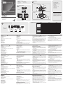
Front View
RS-232 Channel Transmission
VE814T Top View VE814R Top View
Side Top View
Rear View
Installation
© Copyright 2012 ATEN
®
International Co., Ltd.
ATEN and the ATEN logo are trademarks of ATEN International Co., Ltd. All rights reserved.
All other trademarks are the property of their respective owners.
This product is RoHS compliant.
Part No. PAPE-1285-390G
Printing Date: 11 /2012
HDMI Extender over single Cat 5 with
Dual Display
User Guide
VE814
Guide d’utilisation du système d’extension HDMI par câble de catégorie 5 simple avec double af chage VE814
www.aten.com
VE814 HDMI-Verlängerung über einfaches Kat. 5-Kabel mit Zweischirmunterstützung Benutzerhandbuch
www.aten.com
VE814 Alargador HDMI sobre cable de Cat. 5 individual para dos pantallas Manual del usuario
www.aten.com
Estensore HDMI VE814 via Cat 5 singolo con doppio schermo – Guida dell’utente
www.aten.com
8. (Optional) Connect a Internet device to the Ethernet port of the
VE814T/VE814R for the internet connectivity.
Note: Use the dedicated cable holders to secure the power adapter
cables and HDMI cables.
RS-232 Channel Transmission
C
You can connect RS-232 serial devices/peripherals to the VE814,
such as touchscreens and bar code scanners. The RS-232 signal
transmission ow is shown in the following example:
From a source device, the RS-232 signal is transmitted (Tx) to the
VE814T receiving (Rx) unit; the VE814R transmits (Tx) signals to the
display device (Rx).
commande à la plaque à bornes située sur le VE814T ou sur le
VE814R pour réaliser des commandes en série.
7. (Facultatif) Connectez un émetteur/récepteur infrarouge au port
infrarouge du VE814T/VE814R.
8. (Facultatif) Connectez un périphérique d’accès à Internet au port
Ethernet du VE814T/VE814R pour permettre la connexion à
Internet.
Remarque : Use the dedicated cable holders to secure the power
adapter cables and HDMI cables.
Transmission par canal RS-232
C
Vous pouvez connecter des appareils/périphériques série RS-232 au
VE814, notamment des écrans tactiles et des lecteurs de codes-barres.
La transmission du signal RS-232 suit le parcours représenté dans
l’exemple ci-dessous:
À partir d’un périphérique source, le signal RS-232 est transmis (Tx) au
module récepteur VE814T (Rx) ; le module VE814R transmet (Tx) les
signaux au périphérique d’af chage (Rx).
über serielle Befehle steuern zu können.
7. (Optional) Schließen Sie den Infrarot-Sender/-Empfänger an die
Infrarotbuchse des VE814T/VE814R an.
8. (Optional) Verbinden Sie ein Internet-fähiges Gerät mit dem
Ethernet-Anschluss des VE814T/VE814R, wenn Sie einen Internet-
Zugang benötigen.
Hinweis: Verwenden Sie die speziellen Kabelhalter, um die Netz- und
HDMI-Kabel zu sichern.
RS-232-Übertragung
C
Sie können serielle RS-232-Geräte wie z.B. Touchscreens oder
Strichcode-Scanner, an den VE814 anschließen. Das Flussdiagramm
der RS-232-Signalübertragung ist im folgenden Beispiel beschrieben:
Das RS-232-Signal wird von der Signalquelle gesendet (Tx) und von
der VE814T-Empfangseinheit empfangen (Rx); der VE814R sendet (Tx)
die Signale wiederum an das Anzeigegerät (Rx).
6. (Opcional) Conecte su computadora o una controladora al bloque
de terminales del VE814T o VE814R para poder controlar el sistema
con comandos seriales.
7. (Opcional) Conecte el transmisor/receptor de infrarrojos al puerto
para infrarrojos del VE814T/VE814R.
8. (Opcional) Conecte un dispositivo habilitado para Internet al puerto
Ethernet del VE814T/VE814R si desea obtener una conexión de
Internet.
Nota: Utilice los sujetadores para cables dedicados para jar los cables
del adaptador de alimentación y HDMI.
Transmisión por canal RS-232
C
Puede conectar dispositivos o periféricos serie RS-232 tales como
pantallas táctiles o lectores de códigos de barras al VE814. El ujo
de la transmisión de señales RS-232 se representa en el ejemplo
siguiente:
Del dispositivo fuente, la señal RS-232 se transmite (Tx) a la unidad
receptora (Rx) VE814T; el VE814R, a su vez, transmite (Tx) las señales
al dispositivo de visualización (Rx).
8. (Opzionale) Collegare un dispositivo Internet alla porta Ethernet del
VE814T/VE814R per connettersi a Internet.
Nota: utilizzare i portacavi dedicati per ssare i cavi dell’alimentatore e
quelli HDMI.
Trasmissione canale RS-232
C
È possibile collegare dispositivi/periferiche seriali RS-232 al VE814,
come per esempio touchscreen e lettori di codici a barre. Il usso della
trasmissione del segnale RS-232 è illustrato nel seguente esempio:
Il segnale RS-232 è trasmesso (Tx) da un dispositivo sorgente all’unità
ricevente VE814T (Rx), quindi il VE814R trasmette (Tx) i segnali al
dispositivo di visualizzazione (Rx).
Hardware Review
A
Front View
1. Firmware Upgrade button
2. RS-232 Port
3. IR out port
4. IR in port
5. Ethernet Port
6. HDMI IN Port (VE814T)/ HDMI OUT Port (VE814R)
7. HDMI Cable holder
Rear View
1. HDMI Output Port
2. Line IN / OUT Port
3. Power Jack
4. Power cable holder
VE814T Top View
1. HDMI Out LED
Description de l’appareil
A
Vue avant
1. Bouton de mise à niveau du microprogramme
2. Port RS-232
3. Port de sortie infrarouge
4. Port d’entrée infrarouge
5. Port Ethernet
6. Port d'entrée HDMI (VE814T) / Port de sortie HDMI (VE814)
7. Support de câble HDMI
Vue arrière
1. Port de sortie HDMI
2. Port d’entrée/sortie de ligne
3. Prise d’alimentation
4. Support de câble d’alimentation
VE814T Vue supérieure
1. Voyant de sortie HDMI
Hardwareübersicht
A
Vorderseitige Ansicht
1. Taste zur Firmwareaktualisierung
2. RS-232-Port
3. Infrarot-Ausgang
4. Infrarot-Eingang
5. Ethernet-Port
6. HDMI-Eingang (VE814T) / HDMI-Ausgang (VE814R)
7. HDMI-Kabelhalter
Rückseitige Ansicht
1. HDMI-Ausgang
2. Line-In-/Out-Buchse
3. Stromeingangsbuchse
4. Stromkabelhalter
VE814T Draufsicht
1. LED-Anzeige des HDMI-Ausgangs
2. Betriebs- / Verbindungsanzeige
Presentación del hardware
A
Vista frontal
1. Botón de actualización del rmware
2. Puerto RS-232
3. Puerto de salida de infrarrojos
4. Puerto de entrada de infrarrojos
5. Puerto Ethernet
6. Puerto de entrada HDMI (VE814T) / Puerto de salida HDMI (VE814R)
7. Sujetadores para cables HDMI
Vista posterior
1. Puerto de salida HDMI
2. Entrada y salida de línea Line IN / OUT
3. Entrada de alimentación
4. Sujetadores para cable de alimentación
VE814T Vista superior
1. Indicador LED de salida HDMI
Hardware
A
Vista anteriore
1. Pulsante per l’aggiornamento del rmware
2. Porta RS-232
3. Porta uscita infrarossi
4. Porta ingresso infrarossi
5. Porta Ethernet
6. Porta ingresso HDMI (VE814T)/Porta uscita HDMI (VE814R)
7. Portacavo HDMI
Vista posteriore
1. Porta d’uscita HDMI
2. Porta Line IN/OUT
3. Presa d’alimentazione
4. Portacavo alimentazione
VE814T Vista dall’alto
1. LED uscita HDMI
2. Power / Link LED
VE814R Top View
1. HDMI Out 1 LED
2. HDMI Out 2 LED
3. Power / Link LED
Side View
1. Grounding Terminal
Note:
• The LED blinks at 1 second intervals to indicate that the unit is
receiving power, but no connection is made.
• The LED lights steadily to indicate that the connection via Cat 5 cable
is established.
Trouble Shooting
The Firmware upgrade port is reserved for tech support. If you would
like to do rmware upgrade yourself, please contact your dealer.
2. Voyant d’alimentation/de liaison
VE814R Vue supérieure
1. Voyant de sortie HDMI 1
2. Voyant de sortie HDMI 2
3. Voyant d’alimentation/de liaison
Vue latérale
1. Prise de terre
Remarque :
• Le voyant clignote à intervalles d’une seconde a n d’indiquer que
l’unité est alimentée en électricité mais qu’aucune connexion n’est
réalisée.
• Le voyant reste allumé en continu pour indiquer que la connexion par
le biais du câble de catégorie 5 est établie.
Résolution des problèmes
Le port de mise à niveau du microprogramme est réservé à l’assistance
VE814R Draufsicht
1. LED-Anzeige des HDMI-Ausgangs 1
2. LED-Anzeige des HDMI-Ausgangs 2
3. Betriebs- / Verbindungsanzeige
Seitliche Ansicht
1. Erdungsanschluss
Hinweis:
• Die LED-Anzeige blinkt im 1-Sekunden-Intervall, um anzuzeigen,
dass das Gerät zwar eingeschaltet ist, aber noch keine Verbindung
besteht.
• Die LED-Anzeige leuchtet stetig, wenn die Verbindung über das Kat.
5-Kabel hergestellt wurde.
Problemlösung
Der Port zur Firmwareaktualisierung ist nur für Supportzwecke
vorgesehen. Falls Sie selbst eine Firmwareaktualisierung durchführen
möchten, wenden Sie sich an Ihren Fachhändler.
2. Indicador de alimentación / enlace
VE814R Vista superior
1. Indicador LED de salida HDMI 1
2. Indicador LED de salida HDMI 2
3. Indicador de alimentación / enlace
Vista lateral
1. Toma de tierra
Nota:
• El indicador LED parpadea en intervalos de 1 segundo para indicar
que la unidad está encendida pero que todavía no se ha establecido
ninguna conexión.
• El indicador LED se ilumina cuando la conexión a través del cable de
Cat. 5 se ha establecido.
Solución de problemas
El puerto para actualizaciones del rmware está reservado para nes
2. LED alimentazione/collegamento
VE814R Vista dall’alto
1. LED uscita HDMI 1
2. LED uscita HDMI 2
3. LED alimentazione/collegamento
Visione laterale
1. Terminale di messa a terra
Nota:
• Il LED lampeggia a intervalli di 1 secondo per indicare che l’unità
viene alimentata ma non viene effettuata alcuna connessione.
• Il LED rimane acceso sso per indicare che la connessione via Cat 5
è stabilita.
Risoluzione dei problemi
La porta per l’aggiornamento del rmware è riservata all’assistenza
tecnica. Se si desidera effettuare in proprio l’aggiornamento, rivolgersi
al proprio rivenditore.
Hardware Installation
B
1. Connect the HDMI IN Port on the VE814T to the HDMI OUT port on
your video source device using HDMI cable.
2. Connect one end of the RJ-45 cable to the LINE OUT port on the
VE814T.
3. Connect the other end of the RJ-45 cable to the LINE IN port on the
VE814R.
4a. Connect the HDMI OUT port on the VE814T/VE814R to the HDMI
IN port on your video display device using an HDMI cable.
4b. Connect the HDMI OUT port 2 on the VE814R to the HDMI IN port
on your video display device using HDMI cable.
5. Plug the power adapter cable into the power jack on the VE814.
6. (Optional) Connect your computer or controller system to the
terminal block on the VE814T or VE814R to perform serial
commands.
7. (Optional) Connect an IR Transmitter/Receiver to the IR port on the
VE814T/VE814R.
technique. Pour effectuer la mise à niveau vous-même, veuillez
contacter votre distributeur.
Installation du matériel
B
1. Connectez le port d’entrée HDMI du module VE814T au port de
sortie HDMI de votre périphérique vidéo source à l’aide d’un câble
HDMI.
2. Connectez une extrémité du câble RJ-45 au port de sortie de ligne
du module VE814T.
3. Connectez l’autre extrémité du câble RJ-45 au port d’entrée de ligne
du module VE814R.
4a. Connectez le port de sortie HDMI du module VE814T/VE814R au
port d’entrée HDMI de votre périphérique d’af chage vidéo à l’aide
d’un câble HDMI.
4b. Connectez le port de sortie HDMI 2 du module VE814R au port
d’entrée HDMI de votre périphérique d’af chage vidéo à l’aide d’un
câble HDMI.
5. Branchez le câble de l’adaptateur secteur dans la prise d’alimentation
du module VE814.
6. (Facultatif) Connectez votre ordinateur ou votre système de
Hardware installieren
B
1. Verbinden Sie den Eingang HDMI IN am VE814T mit dem HDMI-
Ausgang Ihrer Bildsignalquelle. Verwenden Sie dazu ein passendes
HDMI-Kabel.
2. Verbinden Sie das eine Ende eines RJ-45-Kabels mit der Buchse
LINE OUT am VE814T.
3. Verbinden Sie das andere Ende eines RJ-45-Kabels mit der Buchse
LINE IN am VE814R.
4a. Verbinden Sie den Ausgang HDMI OUT am VE814T/VE814R mit
dem HDMI-Eingang Ihres Anzeigegerätes. Verwenden Sie dazu ein
passendes HDMI-Kabel.
4b. Verbinden Sie den Ausgang HDMI OUT 2 am VE814R mit dem
HDMI-Eingang Ihres Anzeigegerätes. Verwenden Sie dazu ein
passendes HDMI-Kabel.
5. Verbinden Sie das Kabel des Netzteils mit der Stromeingangsbuchse
am VE814.
6. (Optional) Verbinden Sie Ihren Computer oder eine Steuereinheit
mit dem Anschlussblock des VE814T oder VE814R, um die Geräte
de soporte técnico. Si desea actualizar el rmware por su cuenta,
póngase en contacto con su vendedor habitual.
Instalar el hardware
B
1. Conecte el puerto HDMI IN del VE814T a la salida de señal HDMI
de su dispositivo fuente de señal grá ca. Para ello, emplee un cable
HDMI.
2. Conecte un extremo del cable de RJ-45 al puerto LINE OUT del
VE814T.
3. Conecte el otro extremo del cable de RJ-45 al puerto LINE IN del
VE814R.
4a. Conecte el puerto HDMI OUT del VE814T/VE814R a la entrada de
señal HDMI de su dispositivo de visualización. Para ello, emplee un
cable HDMI.
4b. Conecte el puerto HDMI OUT 2 del VE814R a la entrada de señal
HDMI de su dispositivo de visualización. Para ello, emplee un cable
HDMI.
5. Conecte el cable del adaptador de alimentación a la entrada de
alimentación del VE814.
Installazione dell’hardware
B
1. Collegare la porta d’ingresso HDMI del VE814T alla porta di uscita
HDMI del dispositivo video sorgente tramite un cavo HDMI.
2. Collegare un’estremità del cavo RJ-45 alla porta LINE OUT del
VE814T.
3. Collegare l’altra estremità del cavo RJ-45 alla porta LINE IN del
VE814R.
4a. Collegare la porta d’uscita HDMI del VE814T/VE814R alla porta
d’ingresso HDMI del dispositivo video tramite un cavo HDMI.
4b. Collegare la porta d’uscita HDMI 2 del VE814R alla porta d’ingresso
HDMI del dispositivo video tramite un cavo HDMI.
5. Inserire il cavo dell’alimentatore nella presa d’alimentazione del
VE814.
6. (Opzionale) Collegare il computer o il controller alla presa del
VE814T o VE814R per eseguire i comandi seriali.
7. (Opzionale) Collegare il trasmettitore/ricevitore a infrarossi alla porta
infrarossi del VE814T/VE814R.
Online Registration
http://eservice.aten.com
Technical Phone Support
International:
886-2-86926959
North America:
1-888-999-ATEN Ext: 4988
United Kingdom:
44-8-4481-58923
All information, documentation, rmware,
software utilities, and specifications
contained in this package are subject to
change without prior notification by the
manufacturer. Please visit our website
http://www.aten.com/download/?cid=dds
for the most up-to-date versions.
Specifi cations
Function VE814T VE814R
Connectors
HDMI In 1 x HDMI Type A Female (Black) N/A
HDMI Out 1 x HDMI Type A Female (Black) 2 x HDMI Type A Female (Black)
Line In/Out 1 x RJ-45 Female (Silver)
Ethernet 1 x RJ-45 Female (Silver)
RS-232 1 x captive screw connector, 3 pole
IR 2 x 3.5mm phone jack (Black)
Power 1 x DC Jack (Black)
LEDs
Power/Link 1 (Green)
HDMI Out 1 (Green) 2 (Green)
Switch F/W Upgrade Mode 1 x Pushbutton
Resolution 1080p/60Hz, 36bits at 100m
Power Consumption DC5.3V, 8.5W DC5.3V, 13.3W
Environment
Operating Temp. 0–50°C
Storage Temp. -20–60°C
Humidity 0–80% RH, Non-condensing
Physical
Properties
Housing Metal
Weight 0.42 kg 0.43 kg
Dimensions (L x W x H) 14.17 x 10.30 x 3.00 cm

 1
1
 2
2


ATEN VE2812T-AT-U Quick start guide
ATEN VS481 Quick start guide
ATEN VS184 Quick start guide
ATEN UEH4002A Quick start guide