Page is loading ...

User Guide & Instruction Manual
IntelliStation
®
Digital Water Mixing
and Recirculation System
Read this Manual BEFORE using this equipment.
Failure to read and follow all safety and use information can result
in death, serious personal injury, property damage, or damage to the
equipment. Visit PowersControls.com with any questions.
Keep this Manual for future reference.
WARNING
!


LIMITED WARRANTY / LIMITATION OF REMEDY:
What is covered? Powers warrants to the original purchaser only, that the product it
manufactured when used as intended and instructed, is free from defects in materials or
workmanship for five year warranty from date of shipment to the original purchaser.
What is not covered? This Limited Warranty does not cover or is voided by (a) any
product, components or parts not manufactured by Powers, (b) faulty or improper
installation or unsuitable installation environment, (c) failure to follow instructions or
warnings, (d) problems caused by unauthorized attachments, modification, repairs or parts,
(e) negligence or vandalism, (f) problems due to foreign material, adverse or improper
water conditions, chemicals, contamination, improper pH, water treatment activities or
products, mineral deposits, or decomposition by galvanic action, (g) shipping defects
or damage, (h) normal wear and tear, (i) any abuse, misuse, unintended use, failure to
maintain or inspect, (j) any circumstances over which Powers has no control.
IN NO EVENT SHALL POWERS BE LIABLE TO BUYER OR THIRD PARTIES FOR ANY
GENERAL, SPECIAL, INCIDENTAL, OR CONSEQUENTIAL DAMAGES INCLUDING,
BUT NOT LIMITED TO, PROPERTY DAMAGE, PERSONAL INJURIES, LOST PROFITS,
LOSS OF SAVINGS OR REVENUE, LOSS OF THE USE OF THE PRODUCT OR ANY
ASSOCIATED PRODUCTS, COST OF REPAIR, COST OF ANY SUBSTITUTE PRODUCTS
OR SERVICES, DELAY DAMAGES, LABOR CHARGES, FINES/ PENALTIES, ECONOMIC
OR NON-ECONOMIC LOSSES, ARISING DIRECTLY OR INDIRECTLY FROM THE SALE/
PURCHASE, OWNERSHIP, INSTALLATION, OR USE OF THE PRODUCT, WHETHER
BASED ON BREACH OF WARRANTY, BREACH OF CONTRACT, NEGLIGENCE, STRICT
LIABILITY, OR ANY OTHER LEGAL THEORY.
What will Powers do? THE SOLE AND EXCLUSIVE REMEDY UNDER THIS LIMITED
WARRANTY OR ANY IMPLIED WARRANTIES, is: Within a reasonable period of time
after receiving a timely and bona fide claim, Powers will at its sole option (a) repair the
product, or (b) replace the product (or component) with a same or similar product. A
replaced product is warranted for 90 days from the date of return shipment, or for the
balance of the original Limited Warranty period, whichever is longer. IN NO EVENT SHALL
POWERS LIABILITY EXCEED AN AMOUNT EQUAL TO THE SALES PRICE OF THE
PRODUCT.
To obtain warranty service: Contact Powers at 1-800-669-5430 with description of the
problem and proof of the date of original purchase. Cost of shipping and insuring returned
product must be paid by purchaser. Powers is not responsible for any loss of damage to
the product incurred during shipping.
Disclaimer of other warranties: THIS LIMITED WARRANTY IS IN LIEU OF ALL
OTHER WARRANTIES, EXPRESS OR IMPLIED. ALL IMPLIED WARRANTIES,
INCLUDING THE IMPLIED WARRANTIES OF MERCHANTABILITY AND FITNESS FOR
A PARTICULAR PURPOSE, ARE DISCLAIMED.

COMPUTER SYSTEM, NETWORK AND DATA DISCLAIMER:
IntelliStation
®
receives stores and displays data concerning your water distribution system,
performs functions based upon owner/user data input and selections, and can be remotely
programmed and utilized with specified and compatible building automation systems.
AS SUCH, POWERS MAKES NO EXPRESS OF IMPLIED WARRANTY, INCLUDING
WARRANTIES OF MERCHANTABILITY AND FITNESS FOR A PARTICULAR PURPOSE,
REGARDING COMPATIBILITY WITH OTHER TECHNOLOGIES, HARDWARE, SOFTWARE,
NETWORK OR SYSTEMS, THE ACCURACY OR COMPLETENESS OF ANY DATA, THE
SECURITY OF ANY COMPUTER NETWORK OR SYSTEM, OR ANY RESULTS TO BE ACHIEVED
FROM THE INTELLISTATION OR ANY COMPUTER NETWORK OR SYSTEM. POWERS HAS
NO RESPONSIBILITY OR LIABILITY ARISING FROM: THE UNAUTHORIZED USE OF THE
INTELLISTATION; THE CONNECTION TO OR INTEGRATION WITH A USER’S OR ANY OTHER
COMPUTER NETWORK OR SYSTEM; ANY HARDWARE OR SOFTWARE NOT SUPPLIED BY
POWERS; ANY DATA THAT IS INCORRECT, CORRUPT OR CORRUPTED, LOST, STOLEN OR
PIRATED; ANY FAILURE TO SECURE THE INTELLISTATION OR THE USER'S OR ANY OTHER
COMPUTER NETWORK OR SYSTEM; ANY “CRASHING” OR TEMPORARY/PERMANENT
INOPERABILITY OF INTELLISTATION OR ANY COMPUTER NETWORK OR SYSTEM;
ANY UNAUTHORIZED USES, USERS, OR INTRUDERS OF THE INTELLISTATION OR ANY
COMPUTER NETWORK OR SYSTEM; ANY INTENTIONAL OR UNINTENTIONAL VIRUSES OR
CORRUPTION OF ANY KIND OF THE INTELLISTATION OR ANY COMPUTER NETWORK OR
SYSTEM; OR ANY THIRD PARTY ACTION SUCH AS HACKING OR UNAUTHORIZED ACCESS
OR USE OF THE INTELLISTATION OR ANY COMPUTER NETWORK OR SYSTEM.

1
Table of Contents
Introduction ..........................................2
Safety Information......................................3
Understanding Safety Information ..........................3
Radio Frequency Warnings & Hazards .......................3
Intellistation Description & Specifications .....................4
Description of Controls & Functions ........................9
Set up and Programming ...............................20
Sanitization .........................................31
Powers Intellistation BAS Integration Manual .................37
Troubleshooting ......................................52
Scheduled Testing, Inspection and Maintenance ...............63

2
Attention Owners and Users
Thank you for purchasing the Powers IntelliStation
®
. This equipment will provide safe and productive oper-
ation as long as it is installed, set up, used, and serviced in accordance with the instructions in this Manual
and is properly maintained. Owners and users of this equipment have the responsibility to make certain that
this equipment is used properly and safely. To avoid the possibility of death, serious personal injury, property
damage, or damage to the equipment, owners should not permit anyone to touch this equipment unless they
are over 18 years of age, are adequately trained and supervised, and have read and understand this Manual.
Owners should ensure that no unauthorized personnel come in contact with this equipment.
READ THIS MANUAL carefully, learn
how to install, set up, use, service
and maintain this equipment
correctly, and strictly follow all
safety information and instructions
contained in this Manual and on the equipment,
as well as any requirements of local, state, and
federal law. Failure to do so could result in death,
serious personal injury, property damage, or
damage to the equipment. This Manual should be
considered a permanent part of the IntelliStation
and be kept available for easy reference by any
user.
If this equipment, or any of its parts, becomes
damaged or needs repair, stop using the
equipment and contact an experienced service
individual immediately. If the product labels or
this Manual are misplaced, damaged or illegible,
or if you require additional copies, please visit
PowersControls.com.
Please remember that this Manual and the product
labels do not replace the need to be alert, to
properly train and supervise users, and to use
common sense when using this equipment.
If you are ever uncertain about a particular task
or the proper method of operating this equipment,
ask your supervisor, consult this Manual, visit
PowersControls.com, or contact your local sales
representative.
Product Identification
Please record your product’s identification and purchase information which will help in the event you have
questions or need any service.
Model: Date of purchase:
Seller name / address:

3
Understanding Safety Information
This safety-alert symbol is shown
alone or used with a signal word
(DANGER, WARNING, or CAUTION),
a pictorial and/or a safety mes-
sage to identify hazards and alert
you to the potential for death or
serious personal injury.
Identifies hazards which, if not
avoided, will result in death or
serious injury.
Identifies hazards which, if not
avoided, could result in death or
serious injury.
Identifies hazards which, if not
avoided, could result in minor or
moderate injury.
Identifies practices, actions, or
failure to act which could result in
property damage or damage to the
equipment.
• Read the Manual and all product
labels and follow all safety and other
information.
• Learn how to properly and safely use
the equipment BEFORE installing,
set up, using, or servicing.
• Keep the Manual available for easy
access and future reference.
• Replace missing, damaged, or
illegible Manual and product labels.
• Replacement Manuals available at
PowersControls.com
This pictorial alerts you to the
need to read the manual.
This pictorial alerts you to
scalding, burn and hot water
hazards.
This pictorial alerts you to burn
and hot surfaces hazards.
This pictorial alerts you to
electricity, electrocution, and
shock hazards.
This pictorial alerts you to the
need to perform appropriate Lock
Out/ Tag Out procedures.
WARNING
!
CAUTION
!
NOTICE
DANGER
!
!
WARNING
!
TO AVOID DEATH,
SERIOUS PERSONAL
INJURY, PROPERTY
DAMAGE, OR DAMAGE
TO THE EQUIPMENT:
Reading & Understanding the Manual
Important Safety Information

4
The IntelliStation
®
is electronic water mixing system providing user-directed control and monitoring
of water distribution systems. IntelliStation
®
includes an electronic Control Module featuring a color
touchscreen digital display to select desired outlet water temperature, an electronically actuated
valve that mixes hot water with cold water, temperature sensors (plus a quick response temperature
sensor), pressure sensors, check valves, and a recirculation pump to maintain the recirculation loop
temperature (reducing wait time for tempered water to reach point-of-use fixtures, saving water and
energy). The IntelliStation
®
monitors hot supply inlet temperature, hot supply pressure, mixed outlet
temperature, mixed outlet pressure, mixed outlet flow rate (optional), return temperature, and return
pressure, to help maintain the desired outlet water temperature. IntelliStation
®
also features a user
programmable high temperature Sanitization mode to help limit water-borne bacteria as part of a
user-directed and controlled thermal eradication protocol.
The IntelliStation
®
Control Module supports building automation systems (BAS) communication
with BACnet
®
IP, BACnet
®
MSTP, and Modbus
®
protocols, allowing remote programming and
data viewing.
Installation and adjustment of the IntelliStation
®
are the responsibility of the owner and installer and
must be done by qualified personnel in accordance with the manufacturer’s instructions, and com-
plying with all governmental requirements, building and construction codes and standards. It is rec-
ommended to install IntelliStation
®
as part of an ASSE compliant water distribution system, including
mixing valves and/or temperature limiting devices at all point-of-use fixtures (faucets, sinks, tubs,
showers, etc.) that are approved to ASSE 1016, 1069, 1070 and 1071. The owner and user of the
IntelliStation
®
is responsible for selecting and installing the product in an appropriate water distribu-
tion system, proper sizing, maintaining proper water quality/condition, and deciding what tempera-
ture is safe and appropriate for the water distribution users and facility.
IntelliStation Description and Specifications

5
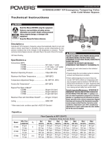
IntelliStation Description and Specifications
The IntelliStation
®
components
are shown below:
Dimensions
18.90
[480.1]
31.28
[794.5]
50.00
[1270.0]
56.32
[1430.5]
3.08
[78.2]
3.24
[82.2]
7.47
[189.6]
10.65
[270.5]
8.25
[209.6]
4.91
[124.8]
LFIS150 IS SHEET LINE ART
56.00
[1422.4]
61.73
[1568.0]
3.25
[82.6]
2.48
[63.0]
19.93 [506.2]
33.28 [845.3]
8.23
[209.0]
11.80
[299.8]
8.13
[206.4]
5.12
[130.0]
LFIS200 IS SHEET LINE ART
LFIS150 LFIS200
Dimensions are shown ±1/2''
Dimensions in parentheses are in mm
P1
T1
T4
T2
P2
T3P4 P3
FT1
Control Unit
Mixed Outlet
Temp & Pressure
Sensors
Hot Temp
& Pressure
Sensors
Electronically
Actuated Valve
Recirc Temp &
Pressure Sensors
Cold Temp &
Pressure Sensors
Recirculation
Pump
Hot
Water
Inlet
Cold
Water
Inlet
Return
Mixed Water
Outlet
To
Boiler

6
Flow Capacity at 50-50 mixed ratio
Pressure Drop Across Valve
Model Min.
System
Draw*
C
V
5psi
(34 kPa)
10psi
(69 kPa)
20psi
(138 kPa)
30psi
(207 kPa)
45psi
(310 kPa)
50psi
(345 kPa)
LFIS150 0.50 26.88
60 gpm
227 lpm
85 gpm
322 lpm
120 gpm
454 lpm
147 gpm
556 lpm
180 gpm
681 lpm
190 gpm
719 lpm
LFIS200 0.50 42.70
96 gpm
363 lpm
135 gpm
511 lpm
191 gpm
723 lpm
234 gpm
886 lpm
286 gpm
1083 lpm
302 gpm
1143 lpm
LFIS150DV 0.50 53.57
120 gpm
454 lpm
170 gpm
644 lpm
240 gpm
908 lpm
294 gpm
1113 lpm
360 gpm
1363 lpm
380 gpm
1439 lpm
LFIS200DV 0.50 85.27
192 gpm
727 lpm
270 gpm
1022 lpm
382 gpm
1446 lpm
468 gpm
1772 lpm
572 gpm
2165 lpm
604 gpm
2286 lpm
LFIS200TV 0.50 127.90
288 gpm
1090 lmp
405 gpm
1533 lpm
573 gpm
2169 lpm
702 gpm
2657 lpm
858 gpm
3248 lpm
906 gpm
3430 lpm
IntelliStation Description and Specifications
Specifications
Maximum Operating Pressure ...................................................... 200psi (1379 kPa)
Maximum Hot Water Temperature ........................................................ 200°F (93°C)
Minimum Hot Water Supply Temp.** ................................ 2°F (1°C) Above Set Point
Hot Water Inlet Temperature Range ...................................... 120 – 180°F (49-82°C)
Cold Water Inlet Temperature Range .......................................... 39 – 80°F (4-27°C)
Minimum Flow*** ....................................................................... 0.5 gpm (1.89 lpm)
Outlet Water Temperature Adjustment Range**** ................... 80 – 180°F (27-82°C)
Listing/Compliance ........................ ASSE1017
®
^, cUPC
®
^, NSF
®
^, CSA 24/UL873,
BACnet Testing Laboratories (BTL)
Ambient Temperature ......................................................32°F (0°C) to 104°F (40°C)
Ambient Humidity ......................................................... 0 - 90% RH non-condensing
SUITABLE FOR INDOOR USE ONLY
** With Equal Pressure
*** Minimum flow when IntelliStation is installed at or near hot water source recirculating tempered water with a
properly sized continuously operating recirculating pump.
**** Low limit cannot be less than the cold water temperature. For best operation, hot water should be at least
5°F (3°C) above desired set point.
Technical Specifications
Input Power ........................ 115/230 V ±10%, 50/60 Hz, 30 VA, 1180 VA fully loaded
Pump relay ............................................ 115/230 V: 10/8 FLA, 50/48 LRA Motor Load
Alert relay: ..................................................... 30 V (ac/dc) max. 2 A, resistive, Class 2
5 V capacity: ...............................................10 mA maximum each, resistive, Class 2
20 V capacity: .............................................20 mA maximum each, resistive, Class 2
Actuator load: ......................................................................................................20 VA
Meets Class B: ..........................................................................ICES and FCC Part 15
Capacity
*With a properly sized pump
^ Listed without re-circulation line & pump
!
User is responsible for determining safe and appropriate
temperatures and pressures for system users, guests and facility.

7
Installation
Failure to follow all installation requirements risks possible death, personal injury,
property damage, and failure of the IntelliStation
®
to perform as intended.
• Installation of IntelliStation
®
MUST be performed by qualified technicians, including licensed electricians
and plumbers, following all manufacturer’s instructions, complying with all local, state, federal and other
governmental requirements, and with all building and construction codes and standards.
• Use ONLY with a potable water distribution system free of debris, foreign materials, corrosive chemicals
or substances, and other adverse conditions.
• IntelliStation
®
is recommended for use as part of an ASSE compliant water distribution system,
including mixing valves and/or temperature limiting devices at all point-of-use fixtures (faucets, sinks,
tubs, showers, etc.).
• IntelliStation
®
MUST be installed indoor in a dry enclosed area not susceptible to the weather elements
such as rain, snow, ice, freezing temperature, direct sunlight or excessive heat.
• Keep work area clean, well-lighted, free of clutter and distractions, and accessible only by authorized
personnel and workers.
• IntelliStation
®
Control Module and touchscreen display must be located in accessible and well-lighted
area for use, servicing, repair or replacement by authorized personnel.
• IntelliStation
®
Control Module is electrically powered. ALWAYS take proper precautions to recognize,
evaluate, and control electricity hazards during installation, programming, use and service/maintenance.
WARNING
!
NOTICE
Installation of IntelliStation
®
is performed by the owner using qualified and licensed trades such as
plumbers and electricians, following all local, state, federal and other governmental requirements, and all
building and construction codes and standards. Step-by-step installation instructions depend upon the
application and the configuration of the building’s water distribution system.
All installations require thorough flushing of all piping BEFORE installation, and testing for and eliminating all
leaks before and after installation.
Check valves are recommended to prevent cross-flow.

8
Mixed Outlet
Pressure Sensor (P1)
Recirc Pressure
Sensor (P2)
Cold Pressure
Sensor (P3)
Hot Pressure
Sensor (P4)
-
+
G
Optional Modbus
®
BAS Connection
R
C
12 4
RCCom
0-10
ActFB
53
Mtr
6
78911121310
FT1 Cs F2 +5V
Not Used
Gnd
1514
20 VF1
(dc)Sup
Ret V
4-20
BACnet
26
27 28 29 30 31 32 33 34
35 36 37 38
CsCs CsT1+5V+5V+5V+5V P4P3
T2 T3
P1 P2
2523 2422
ComCom ComCom
21
39 40
Cs
T4
18 19
Gnd
RS-485
20
+
16 17
Alert
Relay
L
G
N
Recirculation
Pump
115 V (ac)
Power Supply
43 44 45 46
NN
L
Power
Pmp
Recirc Return
Flow Sensor (F2)
Mixed Outlet
Flow Sensor (F1)
Mixed Outlet Temperature
Sensor (T1)
Mixed Outlet Fast
Temperature Sensor
Recirc Return Temperature
Sensor (T2)
Cold Supply Temperature
Sensor (T3)
Hot Supply Temperature
Sensor (T4)
Actuator
Motor
Optional BACnet
®
IP
Connection
Alert Relay
1
8
2
RJ45
F1 Gnd +5 V
Sup V
Control Unit Connections (interior)

9
Control Module and Digital Display
Description of Controls and Functions
The following sections generally outline and describe the controls and functions of the IntelliStation
®
Control
Module you will experience when using the digital display. See “Set Up and Programming” section of this
Manual for use instructions.
The intelligence running the IntelliStation
®
is contained within a Control Module. The color and touch screen
digital display allows the user to view temperatures, pressures, fl ow rates throughout the system, and to
confi gure the controls. The following sections describe and explain the user interface to assist in navigating
and confi guring the control.
After power up, the “Attention!” screen (shown below) will appear. You have 60 seconds to begin system
navigation.
The Control will begin mixing operation after 60 seconds. The “Attention” message will appear again after
10 seconds of inactivity until the 60 seconds time has elapsed.
NOTICE
WARNING
!
Always read the Manual and all product labels
and follow all safety and other information. If
you are ever uncertain about a particular task or
the proper method of operating this equipment,
ask your supervisor, consult this Manual, or visit
PowersControls.com
Start Up Screen

10
Description of Controls and Functions
By touching the screen the user can access the “Home” screen, shown below.
Home Screen
Item Description Units
Mixed Outlet Setpoint
Temperature setpoint °F or °C
Mixed Outlet Temp Temperature measured at the mixing valve outlet °F or °C
Hot Supply Temp Temperature measured at the hot inlet °F or °C
Cold Supply Temp Temperature measured at the cold inlet °F or °C
Recirc Return Temp Temperature measured at the recirculation pump inlet °F or °C
Mixed Outlet Pressure Pressure measured at the mixing valve outlet psi or KPa
Hot Pressure Pressure measured at the mixing valve hot inlet psi or KPa
Cold Pressure Pressure measured at the mixing valve hot inlet psi or KPa
Recirc Pressure Pressure measured at the recirculation pump inlet psi or KPa
Load Flow*
Difference between the mixed and recirc flow rates (F1 and F2)
gpm or m
3
/h or lpm
Mixed Outlet Flow* Flow rate measured at the mixed outlet (F1) gpm or m
3
/h or lpm
Recirc Flow* Flow rate measured on the recirculation return piping (F2) gpm or m
3
/h or lpm
Valve Position Control Voltage supplied to the mixing valve V
Mix Percent Mixed percent hot to total flow, i.e. (Tmixed-Tcold)/(Thot-Tcold) %
*Available on models with optional flow monitoring package
Field 1 Label
Field 1 Select
Field 2 Select
Field 2 Label
Field 1 Value
Field 2 Value
Programming
Menu Access
Pump Status Field
As shown in the screen shot above, there are two fields viewable within the “Home” screen. For instance,
the. Label (item) and Value for Field 1 and Field 2 shown in the Home screen view above are:
Field 1 – “Mixed Outlet Set point” and value of “140°F.”
Field 2 – “Mixed Outlet Temp” and value of “140°F.”
The Label (item) displayed in the fields can be changed by touching the “Field Select” icon to the
right of each field value. The Labels (items) available for viewing on the Home screen by touching the “Field
Select” icon are shown in the table below:
Mixed Outlet Setpoint
140°F
140°F
Mixed Outlet Temp
PRGM Recirc Pump OFF

11
Description of Controls and Functions
Programming Menu
Unlock Function
Also shown on the Home screen is the Pump Status Field (showing if pump is ON or OFF), and the
icon to access the Programming menu.
Touching the icon takes the user to the “Programming” Menu containing six function icons –
“Unlock,” “Setup,” “Monitor,” “Sanitize,” “Home” and “Toolbox” – as shown below:
On the “Programming” Menu the and icons are the only active icons until the control is
unlocked. See “Unlock the System” in the “Set up and Programming” section of this Manual.
Touching the icon takes the user back to the Home Screen.
Touching the icon takes the user to the “Unlock” function screen shown below:
UNLOCK SETUP MONITOR
SANITIZE HOME TOOLBOX
Programming
Unlock
Back Clear Enter
?
1
6
2
7
3
8
4
9
5
0

12
To set and enter a passcode and unlock the system, follow instructions in the “Set Up and Programming”
section of this Manual.
The Set up Function allows the user to access three menus:
■ “System”
■ “Network”
■ “BAS”
The icon on the Unlock function screen is deactivated until the user enters the correct passcode.
The icon will take you back to the Programming Menu.
The icon will show additional information if available.
After entering the correct passcode, the “Setup”, “Monitor”, “Sanitize” and “Toolbox” functions can be
accessed from the “Programming” Menu screen.
The following Sections generally outline and describe these functions.
Touching the icon on the “Programming” Menu will allow access to the Setup function:
Setup Function
Description of Controls and Functions
NOTICE
System Network BAS
Setup
Back
?

13
Description of Controls and Functions
System Menu
Item Field Range
Default
Additional Info
BAS Setpoint Max
80 to Mixed Out
Maximum – 10°F
(max value = 180°F)
140°F
Limit to the remote temperature adjustment (BAS) for
added security and safety. If BAS is set to ‘None’ this
field will not display.
Mixed Out Setpoint
80 to Mixed Out
Maximum – 10°F
(max value = 180°F)
140°F Mixed Outlet setpoint.
High Temp Alert
Mixed Out Setpoint
+10˚F to 190°F
150°F
A mixed outlet temperature over this amount will create
an error condition and issue a reset for the control.
Pump Operation OFF <> ON <> AUTO AUTO
DHW Recirculation pump control mode. AUTO-
temperature differential and dead head protection.
ON-Pump is always on. OFF-Pump is always off.
Pump Head 0.0 to 50.0 psi 8.5 psi
If the head measured across the pump is greater than
this value, the pump will turn/remain off since it can not
generate any flow at these operating conditions (Dead
Head Protection)
Pump Min On/Off Time
0 to 60 min 1 min The minimum time the pump runs or remains off.
Return Target 80°F to 180°F 130°F
The target temperature about which the pump relay
will operate.
Return Differential 1°F to 20°F 10°F
The differential used to determine the pump on and
pump off temperatures.
The System Menu selections are generally described in the table below:
BAS Setpoint Max
140°F
Mixed Out Setpoint
140°F
Pump Operation
Auto
Pump Min On/Off Time
1 min
High Temp Alert
150°F
Pump Head
0.0 psi
Return Target
130°F
Return Differential
Back Up Down
System
Enter
?
10°F

14
Description of Controls and Functions
Network Menu
The Network Menu selections are generally described in the table below:
Item Field Range Default When Displayed Description Additional Info
IP Configuration Manual<> Auto Auto Always
IP Address: 0.0.0.0
Netmask: 0.0.0.0
Gateway: 0.0.0.0
IP Address
0.0.0.1 to
255.255.255.255
192.168.0.1 IP Configuration=Manual
Use keypad entry
0 thru 9
key in IP Address
Buttons on screen
are OK, DEL, TAB,<–,
-->, ?
Subnet Mask
0.0.0.1 to
255.255.255.255
255.255.255.0 IP Configuration=Manual
Use keypad entry
0 thru 9
key in Subnet IP
Address
Buttons on screen
are OK, DEL, TAB,<–,
-->, ?
Gateway Address
0.0.0.1 to
255.255.255.255
192.168.0.1 IP Configuration=Manual
Use keypad entry
0 thru 9
key in Gateway IP
Address
Buttons on screen
are OK, DEL, TAB,<–,
-->, ?
MAC Address aa:bb:ee:ff:11:22
Unique to each
device
Always
MAC Address:
00:04:a3:62:59:8e
IP Configuration
Manual
IP Address
--->
Gateway Address
--->
Subnet Mask
--->
MAC Address
--->
Back Up Down
Network
Enter
?
IP Configuration
Auto
MAC Address
--->
Back Up Down
Network
Enter
?

15
Description of Controls and Functions
BAS Menu
The BAS Menu selections are generally described in the table below:
Item Field Range Default
When
Displayed
Description Additional Info
BAS Type
NONE <> BAC-IP
<> BAC-MSTP
<> MODBUS
NONE Always
Building Automation
Type:
None = control runs in stand alone.
BAC-IP = control is connected to a
BACnet/IP system.
BAC-MSTP = control is connected to a
BACnet/MS-TP system.
MODBUS = control is connected to a
Modbus system.
BACnet
DEVICE ID
0 to 4194303 1
BAS Type = BAC-IP or
BAC-MSTP
Buttons on screen are
OK, DEL,<–, --> ?
BACnet device ID
BACnet Port 1 to 65535 47808 BAS Type = BAC-IP
Use keypad entry 0
thru 9
BACnet Portkey in BACnet PORT
Buttons on screen are
OK, DEL,<–, -->, ?
Register
Foreign Dev
OFF<>ON OFF BAS Type = BAC-IP
Is a BACnet Device that has an IP
subnet address different from those
comprising the BACnet/IP network.
BBMD TIME OFF, 30 to 65535 OFF
BAS Type = BACnet Time-to-live (Seconds)
BACnet Broadcast Management. A
specified time, extending that time by
periodic (automatic) renewal requests.
Register Foreign Dev
≠ OFF
Use keypad entry 0
thru 9
key in BBMD TIME
Buttons on screen are
OK, DEL,<–, -->, ?
BBMD IP
0.0.0.1 to
255.255.255.255
127.127.127.127
BAS Type = BACnet
Use keypad entry0
thru 9
BACnet Foreign device internet Protocol
address. A numerical label assigned to
the foreign device.
Register Foreign Dev≠
OFF
key in IP Address
Buttons on screen are
OK, DEL,<–, --> ?
BBMD PORT 0 to 65535 47808
BAS Type = BACnet
Use keypad entry 0
thru 9
BACnet Broadcat Management Port.
Register Foreign Dev≠
OFF
key in BBMD PORT
Buttons on screen are
OK, DEL,<–, --> ?
BAC-MSTP
Address
0 to 127 1 BAS Type = BAC-MSTP
Buttons on screen are
OK, DEL,<–, --> ?
Set the MSTP address. Each MSTP
device must have a unique address.
BACnet Baud
Rate
9600, 19K2,
38K4, 57K6,
76K8, 115K2
9600 BAS Type = BAC-MSTP Slider, OK,<–, --> ? BACnet MS/TP baud rate
Modbus
Address
1 to 247 1 BAS Type = MODBUS Radio buttons, OK, ?
Modbus Address:
1 to 247
Modbus Data
Type
RTU <> ASCII RTU BAS Type = MODBUS Slider, OK,<–, --> ?
Modbus Data Type
RTU or ASCII
Modbus baud
Rate
1200, 4800,
9600, 14K4,
19K2, 28K8,
38K4, 57K6, 76K,
115K2
9600 BAS Type = MODBUS Slider, OK,<–, --> ? Modbus baud rate
Modbus Parity
None <> Odd
<> Even
Even Slider, OK,<–, --> ? Modbus Parity type.

16
Description of Controls and Functions
Monitor Function
The Monitor Function allows access to the following fields:
Touching the icon on the “Programming” Menu will allow access to the Monitor Function:
Item Field Range
When is it
Displayed
Description Additional Info
Current Error Always The highest priority error code.
Mixed Outlet
High
-22 to 266°F Always
The highest measured mixed outlet
temperature since last cleared.
Mixed Outlet
Low
-22 to 266°F Always
The lowest measured mixed outlet
temperature since last cleared.
Recirc Pump 0-65535 hrs Always
Accumulated run time hours of pump
since last cleared.
Hot Inlet High -22 to 266°F Always
The highest measured hot inlet
temperature since last cleared.
Hot Inlet Low -22 to 266°F Always
The lowest measured hot inlet
temperature since last cleared.
Pressure High 0-65535 psi Always
psi or kPa
The highest measured DHW outlet
pressure since last cleared.
Resolution in tenths
Pressure Low 0-65535 psi Always
psi or kPa
The lowest measured DHW outlet
pressure since last cleared.
Resolution in tenths
Energy
0-65535 Therms
or GJ
Optional F1 and F2 Flow
Sensors present
The accumulated energy usage since
last cleared.
System Supply Sensor
present
System Return Sensor
present
Flow High 0-65535 gpm
Optional F1 and F2 Flow
Sensors present
gpm or m³/h
The largest load flow measured since
last cleared.
Resolution in tenths
Reset All ON<>OFF Always Clear all monitored values to zero.
--- gpm
Mixed Outlet High
109°F
Energy Used
0 MBtu
Hot Inlet High
158°F
Mixed Outlet Low
91°F
Recirc Pump
0 hr
Hot Inlet Low
130°F
Load Flow High
Current Error
---
Back Up Down
System Monitor
Enter
?
/