Drolet-DG04905 11
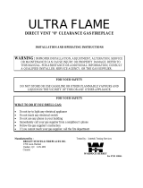
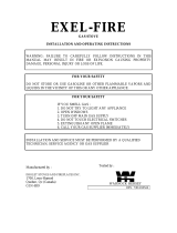
VENT TERMINAL CLEARANCES
REFERENCE LETTER TO DRAWING CANADIAN INSTALLATIONS
1
U.S. INSTALLATIONS
2
A = Clearance above grade,
veranda, porch, deck, or balcony
12 Inches (30 cm) 12 Inches (30 cm)
B = Clearance to window or door
that may be opened
12 Inches (30 cm) 9 Inches (23 cm)
C = Clearance to permanently
closed window
12 Inches (30 cm) 9 Inches (23 cm)
D = Vertical clearance to ventilated
soft located above the terminal
within a horizontal distance of 2
Feet (61 cm) from the center line
of the terminal
18 Inches (46 cm) 18 Inches (46 cm)
E = Clearance to unventilated
soft
18 Inches (46 cm) 18 Inches (46 cm)
F = Clearance to outside corner 12 Inches (30 cm) 12 Inches (30 cm)
G = Clearance to inside corner 12 Inches (30 cm) 12 Inches (30 cm)
H = Clearance to each side
of center line extended above
meter/regulator assembly
3 Feet (91 cm) within a height
15 Feet (4.5m) above the meter/
regulator assembly
Clearance in accordance with
local installation codes and the
requirements of the gas supplier
I = Clearance to service regulator
vent outlet
3 Feet (91 cm) Clearance in accordance with
local installation codes and the
requirements of the gas supplier
J = Clearance to nonmechanical
air supply inlet to building or the
combustion air inlet to any other
appliance
12 Inches (30 cm) 12 Inches (30 cm)
K = Clearance to a mechanical air
supply inlet
6 Feet (1.83 m) 3 Feet (91 cm) above if within 10
Feet (3 m) horizontally
L = Clearance above paved
sidewalk or paved driveway
located on public property
7 Feet (2.13m) A vent shall
not terminate directly above a
sidewalk or paved driveway that
is located between two single
family dwellings and serves both
dwellings
Clearance in accordance with
local installation codes and the
requirements of the gas supplier
M = Clearance under veranda,
porch, deck, or balcony
12 Inches (30 cm) permitted only if
veranda, porch, deck, or balcony
is fully open on a minimum of two
sides
Clearance in accordance with
local installation codes and the
requirements of the gas supplier
1
In accordance with the current CSA-B149.1 Natural Gas and Propane Installation Code
2
In accordance with the current ANSI Z223.1 / NFPA 54 National Fuel Gas Code