Page is loading ...

IMPORTANT: Your new tool has been engineered and manufactured to WEN’s highest standards for dependability,
ease of operation, and operator safety. When properly cared for, this product will supply you years of rugged,
trouble-free performance. Pay close attention to the rules for safe operation, warnings, and cautions. If you use
your tool properly and for its intended purpose, you will enjoy years of safe, reliable service.
NEED HELP? CONTACT US!
Have product questions? Need technical support? Please feel free to contact us:
TECHSUPPOR[email protected]1-800-232-1195 (M-F 8AM-5PM CST)
For replacement parts and the most up-to-date instruction manuals, visit WENPRODUCTS.COM
10-GALLON
AIR COMPRESSOR
Instruction Manual
MODEL 2289

CONTENTS
WELCOME 3
Introduction ..................................................................................................... 3
Specifications ................................................................................................... 3
SAFETY 4
General Safety Rules ........................................................................................ 4
Air Compressor Safety Warnings ..................................................................... 6
Electrical Information ....................................................................................... 7
BEFORE OPERATING 8
Know Your Air Compressor ...............................................................................8
Assembly & Adjustment ................................................................................... 9
OPERATION & MAINTENANCE 9
Operation ......................................................................................................... 9
Maintenance ................................................................................................... 11
Troubleshooting Guide ....................................................................................12
Exploded View & Parts List .............................................................................13
Warranty Statement ....................................................................................... 15
To purchase replacement parts for your tool, visit WENPRODUCTS.COM
2

SPECIFICATIONS
Model Number 2289
Motor 120V, 60 Hz, 15A
Capacity 10 Gallons
Maximum Pressure 150 PSIG
Air Outlet Quick-Coupler, 1/4" NPT
Air Flow
4.0 SCFM at 90 PSI
5.0 SCFM at 40 PSI
Approximate Cut-In Pressure 120 PSIG
Approximate Cut-Out Pressure 150 PSIG
Pump Oil Free
Compression Process Single Stage
Duty Cycle 50%
Product Dimensions 15" x 16" x 32"
Weight 72 Pounds
INTRODUCTION
Thanks for purchasing the WEN Air Compressor. We know you are excited to put your tool to work, but first, please
take a moment to read through the manual. Safe operation of this tool requires that you read and understand this
operator’s manual and all the labels affixed to the tool. This manual provides information regarding potential safety
concerns, as well as helpful assembly and operating instructions for your tool.
NOTE: The following safety information is not meant to cover all possible conditions and situations that may occur.
WEN reserves the right to change this product and specifications at any time without prior notice.
At WEN, we are continuously improving our products. If you find that your tool does not exactly match this manual,
please visit wenproducts.com for the most up-to-date manual or contact our customer service at 1-800-232-1195.
Keep this manual available to all users during the entire life of the tool and review it frequently to maximize
safety for both yourself and others.
SAFETY ALERT SYMBOL: Indicates danger, warning, or caution. The safety symbols and the explanations
with them deserve your careful attention and understanding. Always follow the safety precautions to reduce the
risk of fire, electric shock or personal injury. However, please note that these instructions and warnings are not
substitutes for proper accident prevention measures.
3

GENERAL SAFETY RULES
WORK AREA SAFETY
1. Keep work area clean and well lit. Cluttered or dark
areas invite accidents.
2. Do not operate power tools in explosive atmo-
spheres, such as in the presence of flammable liq-
uids, gases or dust. Power tools create sparks which
may ignite the dust or fumes.
3. Keep children and bystanders away while operating
a power tool. Distractions can cause you to lose control.
ELECTRICAL SAFETY
1. Power tool plugs must match the outlet. Never mod-
ify the plug in any way. Do not use any adapter plugs
with earthed (grounded) power tools. Unmodified plugs
and matching outlets will reduce risk of electric shock.
2. Avoid body contact with earthed or grounded surfac-
es such as pipes, radiators, ranges and refrigerators.
There is an increased risk of electric shock if your body
is earthed or grounded.
3. Do not expose power tools to rain or wet conditions.
Water entering a power tool will increase the risk of elec-
tric shock.
4. Do not abuse the cord. Never use the cord for car-
rying, pulling or unplugging the power tool. Keep cord
away from heat, oil, sharp edges or moving parts.
Damaged or entangled cords increase the risk of electric
shock.
5. When operating a power tool outdoors, use an ex-
tension cord suitable for outdoor use. Use of a cord
suitable for outdoor use reduces the risk of electric
shock.
6. If operating a power tool in a damp location is un-
avoidable, use a ground fault circuit interrupter (GFCI)
protected supply. Use of a GFCI reduces the risk of elec-
tric shock.
PERSONAL SAFETY
1. Stay alert, watch what you are doing and use com-
mon sense when operating a power tool. Do not use a
power tool while you are tired or under the influence
of drugs, alcohol or medication. A moment of inatten-
tion while operating power tools may result in serious
personal injury.
2. Use personal protective equipment. Always wear
eye protection. Protective equipment such as a respira-
tory mask, non-skid safety shoes and hearing protection
used for appropriate conditions will reduce the risk of
personal injury.
3. Prevent unintentional starting. Ensure the switch is
in the off-position before connecting to power source
and/or battery pack, picking up or carrying the tool.
Carrying power tools with your finger on the switch or
energizing power tools that have the switch on invites
accidents.
4. Remove any adjusting key or wrench before turning
the power tool on. A wrench or a key left attached to a
rotating part of the power tool may result in personal
injury.
5. Do not overreach. Keep proper footing and balance
at all times. This enables better control of the power
tool in unexpected situations.
6. Dress properly. Do not wear loose clothing or jew-
elry. Keep your hair and clothing away from moving
parts. Loose clothes, jewelry or long hair can be caught
in moving parts.
Safety is a combination of common sense, staying alert and knowing how your item works. The term “power tool”
in the warnings refers to your mains-operated (corded) power tool or battery-operated (cordless) power tool.
SAVE THESE SAFETY INSTRUCTIONS.
WARNING! Read all safety warnings and all instructions. Failure to follow the warnings and instructions may
result in electric shock, fire and/or serious injury.
4

GENERAL SAFETY RULES
7. If devices are provided for the connection of dust
extraction and collection facilities, ensure these are
connected and properly used. Use of dust collection
can reduce dust-related hazards.
POWER TOOL USE AND CARE
1. Do not force the power tool. Use the correct power
tool for your application. The correct power tool will
do the job better and safer at the rate for which it was
designed.
2. Do not use the power tool if the switch does not turn
it on and off. Any power tool that cannot be controlled
with the switch is dangerous and must be repaired.
3. Disconnect the plug from the power source and/or
the battery pack from the power tool before making
any adjustments, changing accessories, or storing
power tools. Such preventive safety measures reduce
the risk of starting the power tool accidentally.
4. Store idle power tools out of the reach of children
and do not allow persons unfamiliar with the power
tool or these instructions to operate the power tool.
Power tools are dangerous in the hands of untrained us-
ers.
5. Maintain power tools. Check for misalignment or
binding of moving parts, breakage of parts and any
other condition that may affect the power tool’s opera-
tion. If damaged, have the power tool repaired before
use. Many accidents are caused by poorly maintained
power tools.
6. Keep cutting tools sharp and clean. Properly main-
tained cutting tools with sharp cutting edges are less
likely to bind and are easier to control.
7. Use the power tool, accessories and tool bits, etc.
in accordance with these instructions, taking into ac-
count the working conditions and the work to be per-
formed. Use of the power tool for operations different
from those intended could result in a hazardous situa-
tion.
8. Use clamps to secure your workpiece to a stable
surface. Holding a workpiece by hand or using your
body to support it may lead to loss of control.
9. KEEP GUARDS IN PLACE and in working order.
SERVICE
1. Have your power tool serviced by a qualified repair
person using only identical replacement parts. This
will ensure that the safety of the power tool is main-
tained.
CALIFORNIA PROPOSITION 65 WARNING
Some dust created by power sanding, sawing, grinding,
drilling, and other construction activities may contain
chemicals, including lead, known to the State of Califor-
nia to cause cancer, birth defects, or other reproductive
harm. Wash hands after handling. Some examples of
these chemicals are:
• Lead from lead-based paints.
• Crystalline silica from bricks, cement, and other
masonry products.
• Arsenic and chromium from chemically treated
lumber.
Your risk from these exposures varies depending on
how often you do this type of work. To reduce your ex-
posure to these chemicals, work in a well-ventilated area
with approved safety equipment such as dust masks
specially designed to filter out microscopic particles.
Safety is a combination of common sense, staying alert and knowing how your item works. The term “power tool”
in the warnings refers to your mains-operated (corded) power tool or battery-operated (cordless) power tool.
SAVE THESE SAFETY INSTRUCTIONS.
WARNING! Read all safety warnings and all instructions. Failure to follow the warnings and instructions may
result in electric shock, fire and/or serious injury.
5

AIR COMPRESSOR SAFETY
1. Do not use your air compressor if the pressure switch
does not turn the compressor on and off. An air com-
pressor that cannot be controlled with the switch is dan-
gerous and must be repaired.
2. Disconnect the plug from the power source and drain
all air from the tank before making any adjustments,
changing accessories, or storing your air compressor.
This reduces the risk of starting your air compressor ac-
cidentally.
3. Store your air compressor out of the reach of children
and do not allow people unfamiliar with either the com-
pressor or these instructions to operate it. An air com-
pressor is dangerous in the hands of an untrained user.
4. Maintain your air compressor. Keep your air compres-
sor clean for maximum performance. Follow the instruc-
tion for maintenance and changing accessories if neces-
sary. Keep your air compressor dry, clean and free from
oil and grease.
5. Check for misalignment or binding of moving parts,
breakage of parts and any other condition that may af-
fect your air compressor’s operation. If damaged, have
your air compressor repaired by a qualified service tech-
nician before using it again. Many accidents are caused
by poorly maintained compressors.
6. Use your air compressor in accordance with these in-
structions, taking into account working conditions and
the task at hand. Use of the compressor for operations
other than its intended use could result in personal in-
jury.
7. Do not spray flammable liquids in a confined area or
towards a hot surface. The spray area must be well-ven-
tilated. Do not smoke while spraying. Do not spray when
a spark or flame is present.
8. Always operate the compressor in a well-ventilated
area away from combustible materials, gasoline, or sol-
vent vapors. Your air compressor must be kept at least
20 feet away from explosive vapors.
9. Do not adjust the regulator higher than the marked
maximum pressure of any attached pneumatic tools or
equipment.
10. Do not direct the air stream at people or animals.
11. Do not use to supply breathing air.
12. Do not leave your air compressor unattended for an
extended period while plugged in. Unplug compressor
and detach hoses and accessories after use.
13. Keep your air compressor in a well-ventilated area.
Do not cover during use.
14. Drain tank daily or after use. Internal rust causes
tank failures and explosions.
15. To prevent burns or other injuries, do not touch any
exposed metal parts on compressor during or immedi-
ately after operation. The air compressor’s cylinder head
and air lines get hot during operation, and will remain
hot for several minutes after operation.
16. Do not use the air hose to move your air compressor.
17. Do not grind, puncture, torch or in anyway modify
the compressor’s tank.
18. Ignoring any of the above rules and guidelines auto-
matically voids the warranty for the unit.
AIR COMPRESSOR SAFETY WARNINGS
WARNING! Do not operate the power tool until you have read and understood the following instructions and
the warning labels.
6

ELECTRICAL INFORMATION
AMPERAGE
REQUIRED GAUGE FOR EXTENSION CORDS
25 ft. 50 ft. 100 ft. 150 ft.
15A 14 gauge 12 gauge Not Recommended Not Recommended
3. Check
with a licensed electrician or service personnel if you do not completely
understand the grounding instructions or whether the tool is properly grounded.
4. Use only three-wire extension cords
that have three-pronged plugs and outlets
that accept the tool’s plug. Repair or replace a damaged or worn cord immediately.
CAUTION!
In all cases, make certain the outlet in question is properly grounded. If
you are not sure, have a licensed electrician check the outlet.
GUIDELINES AND RECOMMENDATIONS FOR EXTENSION CORDS
When using an extension cord, be sure to use one heavy enough to carry the current
GROUNDING INSTRUCTIONS
In the event of a malfunction or breakdown
, grounding provides the path of least resistance for an electric
current and reduces the risk of electric shock. This tool is equipped with an electric cord that has an
equipment grounding conductor and a grounding plug. The plug MUST be plugged into a matching outlet
that is properly installed and grounded in accordance with ALL local codes and ordinances.
1. Do not modify the plug provided.
If it will not fit the outlet, have the proper outlet installed by a licensed
electrician.
2. Improper connection
of the equipment grounding conductor can result in electric shock. The conductor
with the green insulation (with or without yellow stripes) is the equipment grounding conductor. If repair or
replacement of the electric cord or plug is necessary, DO NOT connect the equipment grounding conductor
to a live terminal.
1. Examine extension cord before use. Make sure your extension cord is properly wired and in good condition.
Always replace a damaged extension cord or have it repaired by a qualified person before using it.
2. Do not abuse extension cord. Do not pull on cord to disconnect from receptacle; always disconnect by pulling on
plug. Disconnect the extension cord from the receptacle before disconnecting the product from the extension cord.
Protect your extension cords from sharp objects, excessive heat and damp/wet areas.
3. Use a separate electrical circuit for your tool. This circuit must not be less than a 12-gauge wire and should be
protected with a 15A time-delayed fuse. Before connecting the motor to the power line, make sure the switch is in
the OFF position and the electric current is rated the same as the current stamped on the motor nameplate. Running
at a lower voltage will damage the motor.
your product will draw. An undersized cord will cause a drop in line voltage resulting in loss of power and overheat-
ing. The table below shows the correct size to be used according to cord length and ampere rating. When in doubt,
use a heavier cord. The smaller the gauge number, the heavier the cord.
Fig. 1
7

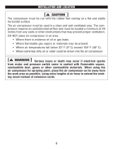
KNOW YOUR AIR COMPRESSOR
TOOL PURPOSE
Plug in nailers, staplers, spray guns, or any other pneumatic tool to your WEN air compressor for a versatile and
dependable set-up that answers a variety of woodworking and painting needs. Refer to the following diagrams to
become familiarized with all the parts and controls of your air compressor. The components will be referred to later
in the manual for assembly and operation instructions.
Regulated Pressure Gauge
8
Pressure Release Valve
Air Line Inlet
Air Pressure Regulator
Tank
Tank Drain Valve
Handle
Air Filter
Motor
Tank Pressure Gauge
Pressure Switch

9
ASSEMBLY & ADJUSTMENTS
INSTALLING THE WHEELS
1. Insert the bolt (Fig. 2 - 1) into the wheel (Fig. 2 - 2), through the wheel bracket (Fig. 2 - 3), through the flat washer
(Fig. 2 - 4), and install the nut (Fig. 2 - 5). Tighten the nut.
INSTALLING THE AIR FILTER
1. Remove the plastic plug as instructed on the yellow hang tag on the unit. Install the air filter (Fig. 3 - 1).
Fig. 3
1
OPERATION
STARTING THE COMPRESSOR
1. Follow all instructions in the assembly guidelines outlined
above before attempting to start the compressor. Do not start
the compressor until the air filter has been properly installed.
2. Inspect the machine components to make sure that there are
no damaged or worn parts. Replace any damaged parts imme-
diately. Only repair using identical replacement parts.
3. Check that the pressure switch (Fig. 4 - 1) is turned to the OFF
position and the tank drain valve (Fig. 4 - 2) is closed.
4. Connect an air hose (not included) to the air line inlet (Fig.
5 - 1). The air hose must be rated to exceed the compressor’s
maximum pressure of 150 PSIG.
5. Connect the electrical plug to a power supply.
NOTE: The compressor must be at least one foot from any wall
or obstruction and in a well-ventilated area in order to maximize
proper air flow. Do not cover the compressor.
6. Turn the pressure switch (Fig. 4 - 1) to the ON/AUTO posi-
tion to allow the compressor to automatically start up and shut
down, depending on its need for air.
Fig. 2
1
2
3
4
5
Fig. 4
1
2
Fig. 5
1

10
OPERATION
NOTE: the compressor will not turn ON if the tank pressure is
above the cut-in pressure. Once the tank pressure drops below
the cut-in pressure, the compressor will automatically start up,
and then automatically shut down once the cut-out pressure is
reached.
NOTE: make sure this switch is set to OFF before unplugging,
plugging in, or storing the compressor.
7. Allow the compressor to reach the desired pressure on the tank pressure gauge (Fig. 6 - 1) before turning off
the compressor. If left on, the compressor will reach its maximum pressure of 150 PSIG and turn off automatically.
Once the tank pressure drops to the preset cut-in pressure value, the compressor will automatically turn back on
until it reaches its maximum tank pressure again. Check the tank pressure gauge (Fig. 6 - 1). DO NOT ALLOW THE
COMPRESSOR TO FILL UP TO MORE THAN 150 PSIG.
8. Turn the air pressure regulator knob (Fig. 6 - 2) to the desired position in order to control the air output from the
compressor. The regulated air pressure gauge (Fig. 6 - 3) will show you the current air pressure from the air line
outlet. Make sure that this pressure is not higher than the working pressure of any pneumatic tools hooked up to the
compressor. Using a pressure higher than the rated pressure of an attached tool creates the possibility of damaging
or, in worse case scenarios, bursting said pneumatic tool. Using a pressure that is too low for a tool can result in
misfires and improper functionality.
WARNING! To prevent burns or other injuries, DO NOT
touch the compressor while it is running. Allow it to cool
before handling or servicing. Keep children away from the
compressor at all times.
Fig. 6
1
2
SHUTTING DOWN THE COMPRESSOR
1. Turn the pressure switch to the OFF position. Then unplug the
power cord.
2. Reduce pressure in the tank through the outlet hose or by
pulling the relief valve ring (Fig. 7 - 1).
3. Drain water from air tank by opening drain valve (counter-
clockwise) on the bottom of the tank.
WARNING! Wear safety goggles when opening drain
valve. Escaping air and moisture may propel debris that may
cause eye injury.
DUTY CYCLE
The motor and pump on your compressor are capable of running continuously, but in order to prolong your air
compressor’s life, it is recommended that a 50% duty cycle be maintained; that is, the air compressor motor and
pump should not run for more than 30 minutes in any given hour.
1
Fig. 7
3

11
MAINTENANCE
WARNING! Always shut off and unplug the compressor and relieve all air pressure from the system before
performing any cleaning or inspection on the air compressor.
CLEAN AND INSPECT DAILY
1. Pull the pressure release valve ring to open the pressure release valve after each operation. The pressure release
valve should automatically close when tank pressure reaches approximately 40 – 50 PSIG. If it does not automati-
cally close, it needs to be replaced. Contact WEN customer service for assistance.
2. Open the tank drain valve underside the compressor to drain the tank daily after each operation. To minimize
moisture inside of the unit, tip the compressor during drainage so that the drain valve is aimed directly towards the
ground. This will allow all moisture to drain completely and prevent the tank from corrosion.
3. Wipe the tool clean. Blow the tool clean using compressed air (which, believe it or not, you can get from your
air compressor), then use non-flammable cleaning solutions to wipe exterior of the tool as necessary, particularly
before storage. Do not soak tool with cleaning solutions. Such solutions can damage internal parts. Keep the handle
clean, dry, and free from slippery substances such as oil or grease.
4. Inspect the machine components before operation to make sure that there are no damaged or worn parts. Re-
place any damaged parts immediately. Do not operate if there are any damaged components. Only repair using
identical replacement parts.
5. Do not overtighten connections to avoid creating leaks.
6. Your compressor is oil-free, and requires no external lubrication
AIR FILTER MAINTENANCE
Check the air filter weekly in a dirty shop environment, and monthly in a clean shop environment. Replace the air
filter if it is clogged. A clean air filter will prolong the life of your compressor. Replacement air filters can be pur-
chased from wenproducts.com.
TESTING FOR LEAKS
Make sure all connections are tight and secure before testing for leaks. A small leak in any hoses or connectors will
greatly reduce the abilities of the compressor. To locate a leak, simply spray a mixture of soap and water across the
entire surface of both the tank and the hose (wherever the leak is believed to be). Bubbles will begin to appear if
a leak is indeed present. Fix immediately. Try to avoid getting soapy water near any of the inlets on the tank or the
pump.
STORAGE
Before storing the compressor, drain the tank by opening the tank drain valve on the underside of the compressor
(Fig. 4 - 2). This will drain the tank and help prevent moisture from collecting on and rusting the inside of the tank.
Do not store your compressor in cold climates, as cold climates may create problems with the motor and pump
seals, while possibly freezing water condensation inside the tank.

12
TROUBLESHOOTING GUIDE
WARNING! Stop using the generator immediately if any of the following problems occur or risk serious
personal injury. If you have any questions, please contact customer service at 1-800-232-1195 (M-F 8-5 CST),
or email [email protected].
Problem Possible Cause Solution
Air leaks from the regulator.
Regulator does not regulate
pressure anymore.
Regulator is damaged or dirty.
Replace regulator. Call 1-800-232-1195 for as-
sistance.
Low pressure, and/or com-
pressor does not cut out
automatically.
Tank drain valve is open. Close drain valve.
Leak somewhere on the unit, air hose,
connection, etc.
Check for leaks; see “Testing for Leaks” on p.
11.
WARNING: If tank leaks, it must be replaced
immediately. DO NOT attempt to repair.
Tool using too much air, or compressor
is too small.
Check tool’s CFM requirements. Make sure this
compressor’s specifications meet the require-
ments.
Air intake obstructed, or air filter dirty.
Make sure unit is away from walls, and that the
air inlets are not obstructed. Check air filter.
Worn pressure switch contacts.
Check contacts; pressure switch may need
replacement.
Blown gasket/seal, or leaking valve/pis-
ton ring(s).
Replace parts. Contact 1-800-232-1195 for
assistance.
Motor does not start (hum-
ming sound).
Bad capacitor.
Replace part. Contact 1-800-232-1195 for as-
sistance.
Centrifugal switch is stuck.
Reset centrifugal switch. Call 1-800-232-1195
for assistance.
Motor does not start (no
humming sound).
Power source is not working.
Check power source. Ensure line voltage is high
enough and extension cord (if applicable) is an
appropriate size.
Check valve stuck open.
Clean or replace check valve. Call 1-800-232-
1195 for assistance.
Pressure relief valve opens
automatically at improper
pressure.
Tank pressure is too high, or pressure
switch is stuck.
Replace pressure switch. Call 1-800-232-1195
for assistance.

EXPLODED VIEW & PARTS LIST
13
32
2
29
10
27
26
34
23A
33
6
7
14
12
13
39
15A
9
8
18
20
21
36
38
28
25
24
32
29
36
38
31
4
5
16
1
40
3
22
35
37
30
17
19
11

EXPLODED VIEW & PARTS LIST
No. Model No. Description Qty.
1 2289-001 Pump Assembly 1
2 2289-002 Rubber Foot 2
3 2289-003B Shroud Front 1
4 2289-004B Shroud Rear 1
5 2289-005 Air Filter Intake Housing 1
6 2289-006 6' Power Cord 1
7 2289-007 Pressure Switch 1
8 2289-008 Pressure Gauge 2
9 2289-009 Safety Valve 1
10 2289-010 Drain Valve 1
11 2289-011 Check Valve 1
12 2289-012 Regulator 1
13 2289-013 Quick Connect Fitting 1
14 2289-014 Nipple 35mm 1
15A 2289-015A
Vertical Pipe Nipple
Assembly
1
16 2289-016 Exhaust Elbow 1
17 2289-017 3/8" Ferrule Tubing 2
18 2289-018 1/4" Ferrule Tubing 2
19 2289-019 3/8" Nut 2
20 2289-020 1/4" Nut 2
14
No. Model No. Description Qty.
21 2289-021 Relief Tube 1
22 2289-022 Outlet Tube 1
23A 2289-023A 10-Gallon Tank 1
24 2289-024 Handle 1
25 2289-025 Rubber Grip 1
26 2289-026 Wheel 2
27 2289-027 Bolt M10x1.25x55 2
28 2289-028 Hex Bolt M8x1.25x25mm 4
29 2289-029 Hex Bolt M8x1.25x20mm 6
30 2289-030 Hex Bolt M6x1.0x20 2
31 2289-031 Hex Bolt M6x1x12mm 6
32 2289-032 Hex Nut M8 6
33 2289-033 Nylon Hex Nut M10x1.25 2
34 2289-034 Flat Washer M10 2
35 2289-035 Flat Washer 6mm 2
36 2289-036 Flat Washer 8mm 8
37 2289-037 Lock Washer 6mm 2
38 2289-038 Lock Washer M8 8
39 2289-039 O Ring 1
40 2289-040 Screw 2

15
WARRANTY STATEMENT
WEN Products is committed to building tools that are dependable for years. Our warranties are consistent with this
commitment and our dedication to qualit
y.
LIMITED WARRANTY OF WEN PRODUCTS FOR HOME USE
GRE
AT LAKES TECHNOLOGIES, LLC (“Seller”) warrants to the original purchaser only, that all WEN
consumer
power tools will be free from defects in material or workmanship during personal use for a period of two (2) years
from
date of purchase or 500 hours of use; whichever comes first. Ninety days for all WEN products if the tool
is
used
for professional or commercial use. Purchaser has 30 days from the date of purchase to report missing
or
damaged parts.
SELLER’S
SOLE OBLIGATION AND YOUR EXCLUSIVE REMEDY under this Limited Warranty and, to the extent per-
mitted
by law, any warranty or condition implied by law, shall be the replacement of parts, without charge, which
are
defective
in material or workmanship and which have not been subjected to misuse, alteration, careless
handling,
misrepai
r, abuse, neglect, normal wear and tear,
improper maintenance, or other conditions adversely affecting the
Product
or the component of the Product, whether by accident or intentionally, by persons other than Seller. To
make
a claim under this Limited Warranty, you must make sure to keep a copy of your proof of purchase that
clearly
defines the Date of Pur
chase (month and year) and the Place of Purchase. Place of Purchase must be a direct ven-
dor
of Great Lakes Technologies, LLC. Purchasing through third party vendors, including but not limited to
garage
sales,
pawn shops, resale shops, or any other secondhand merchant, voids the warranty included with this
product.
Contact [email protected] or 1-800-232-1195 with the following information to make arrangements:
your
shipping address, phone number, serial number, required part numbers, and proof of purchase. Damaged
or
defective parts and products may need to be sent to WEN before the replacements can be shipped out.
Upon
the confirmation of a WEN representative, your product may qualify for repairs and service work. When re-
turning
a product for warranty service, the shipping charges must be prepaid by the purchaser. The product
must
be
shipped in its original container (or an equivalent), properly packed to withstand the hazards of shipment.
The
product
must be fully insured with a copy of the proof of purchase enclosed. There must also be a description of
the
problem
in order to help our repairs department diagnose and fix the issue. Repairs will be made and the
product
will be returned and shipped back to the pur
chaser at no charge for addresses within the contiguous United States.
THIS
LIMITED WARRANTY DOES NOT APPLY TO ITEMS THAT WEAR OUT FROM REGULAR USAGE OVER
TIME,
INCLUDING
BELTS, BRUSHES, BLADES, BATTERIES, ETC. ANY IMPLIED WARRANTIES SHALL BE LIMITED
IN
DURA
TION TO TWO (2) YEARS FROM DATE OF PURCHASE. SOME STATES IN THE U.S. AND SOME
CANADIAN
PROVINCES
DO NOT ALLOW LIMITATIONS ON HOW LONG AN IMPLIED WARRANTY LASTS, SO THE ABOVE LIMI-
TA
TION MAY NOT APPLY TO YOU.
IN
NO EVENT SHALL SELLER BE LIABLE FOR ANY INCIDENTAL OR CONSEQUENTIAL DAMAGES
(INCLUDING
BUT
NOT LIMITED TO LIABILITY FOR LOSS OF PROFITS) ARISING FROM THE SALE OR USE OF THIS PRODUCT.
SOME ST
ATES IN THE U.S. AND SOME CANADIAN PROVINCES DO NOT ALLOW THE EXCLUSION OR LIMITA
TION
OF
INCIDENTAL OR CONSEQUENTIAL DAMAGES, SO THE ABOVE LIMITATION OR EXCLUSION MAY NOT APPLY
TO YOU.
THIS
LIMITED WARRANTY GIVES YOU SPECIFIC LEGAL RIGHTS, AND YOU MAY ALSO HAVE OTHER
RIGHTS
WHICH
VARY FROM STATE TO STATE IN THE U.S., PROVINCE TO PROVINCE IN CANADA AND FROM COUNTRY
TO COUNT
RY.
THIS
LIMITED WARRANTY APPLIES ONLY TO ITEMS SOLD WITHIN THE UNITED STATES OF AMERICA, CANA-
DA
AND THE COMMONWEALTH OF PUERTO RICO. FOR WARRANTY COVERAGE WITHIN OTHER
COUNTRIES,
CONT
ACT THE WEN CUSTOMER SUPPORT LINE. FOR WARRANTY PARTS OR PRODUCTS REPAIRED
UNDER
W
ARRANTY SHIPPING TO ADDRESSES OUTSIDE OF THE CONTIGUOUS UNITED STATES, ADDITIONAL
SHIPPING
CHARGES MAY APPLY.

THANKS FOR
REMEMBERING
V. 2019.11.19
/