Page is loading ...

DYN3106 / DYN3206 / DYN3306
1 – 3 Person Saunas
OWNER’S MANUAL
FOR CARBON MODEL SAUNAS
INDOOR USE ONLY
120VAC 15 AMP ( 1 & 2-PERSON MODELS) DEDICATED CIRCUIT
120VAC 20 AMP (3-PERSON MODELS) DEDICATED CIRCUIT
Sauna: Now you can enjoy the European secret for youthful vitality.
Carefully and thoroughly read this manual before using the sauna. We
recommend keeping this manual for regular review and future reference.

*PLEASE READ INSTRUCTIONS BEFORE
ASSEMBLY*
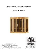
DYN-3106
DYN-3206
*The above assembly diagrams are for quick
reference
visual guides only.
All sauna models are not shown. Parts and accessories may
vary.

*PLEASE READ INSTRUCTIONS BEFORE
ASSEMBLY*
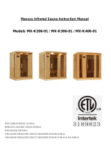
DYN-3306
*The above assembly diagram is for a quick
reference
visual guide only. All
sauna models are not shown. Parts and accessories may
vary.

4
WHAT ARE INFRARED RAYS?
Infrared is the band of light we perceive as heat. We cannot see this band of light with the naked eye, but we
can feel this type of light in the form of heat. Our sun produces most of its energy output in the infrared
segment of the spectrum. Infrared rays heat your body without having to heat the air in-between. This process
is called conversion.
The infrared is divided into 3 segments by wavelengths measured in microns: near infrared: 0.76-1.5
microns; middle infrared: 1.5-5.6 microns; and far infrared: 5.6-1000 microns. Among these segments, only
far infrared penetrates organic substances such as the human body two to three inches so that the
warming effect is very uniform.
ARE INFRARED RAYS SAFE?
Because infrared rays are part of sunlight, they are not only safe but also highly beneficial to our bodies on a
cellular level. Health professionals have used infrared heat lamps for decades to treat muscle and joint
problems. In hospital baby care units, incubators are often equipped with infrared heating systems to keep
newborn babies warm.

5
HOW IT WORKS
Infrared Saunas differ from traditional saunas in that they use infrared radiant energy to directly penetrate into
the body's tissue to produce perspiration.
Traditional saunas use steam to heat the air inside the sauna, which then heats your body until you begin to
perspire. In order for this to be effective, temperatures would need to reach in the upwards of 190 degrees
Fahrenheit. Infrared saunas only need a temperature of up to 120 degrees Fahrenheit to obtain the same
effect. This lower temperature makes the environment more tolerable and allows you to breathe easier.
BENEFITS
Because infrared rays penetrate the body through conversion, there is a deep heating effect in both the muscle
tissues and internal organs without putting too much burden on the heart.
Our body reacts to the increased heating through the natural cooling process of perspiring. Through the
perspiration process, acid and waste residue like toxins, sodium, alcohol, nicotine, cholesterol and the
potentially carcinogenic heavy metals are removed from the cells (especially zinc, lead, nickel, cadmium,
etc). The pores of our skin open and discharge waste products shedding any old skin cells leaving the skin
glowing and clean, with improved tone, elasticity, texture, and color.
Over the last 25 years, Japanese and Chinese researchers and clinicians have completed extensive research
on infrared treatments and have reported many provocative findings. In Japan, there is an "infrared society"
composed of medical doctors and physical therapists dedicated to furthering infrared research. Their findings
support the health benefits of infrared therapy as a method of healing.

6
Benefits include, but are not limited to:
- Pain relief from Rheumatoid Arthritis
- Relaxing muscle spasms
- Increases blood circulation
- Cardiovascular conditioning
- Clears rashes, acne
- Reduces cellulite
- Removes toxins and mineral waste
- Reduces stress and fatigue
- Enhances skin tone
SAUNA MAINTENANCE
Since infrared saunas do not require hot rocks, water, or steam to operate, they require very little
maintenance. You can simply wipe it down with water and a soft clean cloth. Do not use any cleaning
chemicals as they can be absorbed into the wood and be released into your sauna during use.
DISCLAIMER
The infrared rays emitted by your sauna are reported to offer a wide range of possible therapeutic benefits
based on research completed over the last 25 years from all around the world. These benefits are presented
for reference purposes only and no implication of infrared saunas creating a cure for or treating any disease is
implied nor should it be inferred. If you have a health condition, are taking prescription drugs, or have acute
joint injuries, please consult your physician before starting infrared therapy. Persons with surgical implants
(metal pins and rods, artificial joints, silicone, or other types of surgical implants) typically do not experience
any adverse effects, but should also consult their physician or surgeon before starting infrared therapy.
CAUTION: Exit sauna immediately if you feel dizzy,
sleepy, or any discomfort.

7
TABLE OF CONTENTS
Product Introduction 7
Parts Description 8
Assembly Instructions 13
Operating the Sauna 19
Tips for Using Your Sauna 21
Safety Instructions 22
Safeguards for Your Sauna 23
Troubleshooting Guide 23
Warranty 25
Warranty Card 27
WARNING: Visually inspect all heaters before assembly to make sure they are not
damaged. Any excessive vibrations during transport could cause damage to the
heating elements. DO NOT START the sauna if damage is detected! Contact your
dealer or manufacturer for troubleshooting and replacement parts.
1. Product Introduction
The infrared sauna room is composed of a wood cabin, infrared heat emitters, and a control system. The
wood cabin includes a FLOOR PANEL, RIGHT SIDE WALL PANEL, FRONT PANEL with GLASS DOOR,
LEFT SIDE WALL PANEL, REAR WALL PANEL, ROOF PANEL, BENCH HEAT EMITTER PANEL, and
BENCH. The infrared sauna comes with an interior control panel, drink shelf (optional), reading lamp, MP3
AUX Input jack, speakers, and infrared heat emitters.
NOTE: The pictures and diagrams shown within this owner’s manual are representations of this model.
Actual model may vary.

8
PARTS DESCRIPTION
DYN-3106
DYN-3206

9
DYN-3306

10
I. Power Supply (Control Box)
The POWER SUPPLY BOX is the control center of the sauna room. It is installed on the ROOF PANEL and
has input/outputs connected to it as seen below. (see Figure 1)
Figure 1
MAIN POWER main power of the sauna room
HT1, HT2, HT3, HT4 emitter power output cords
LIGHT reading lamp power output cord
ROOF LAMP roof lamp power output cord (optional)
CTRL control panel connection
CD/SIG signal cable group
II. Component Labeling
POWER Power Cord
HT1, HT2, HT3, HT4 Emitter (heater) power cords
LIGHT Reading lamp connector
ROOF LAMP Roof lamp connector (not available on all models)
COLOR LAMP Color lamp connector (not available on all models)
CTRL Control panel connector
CD/SIG For speakers/temperature sensor/buzzer/etc. connectors
CD-POWER CD/radio power connector (not available on all models)
FAN-POWER CD/radio fan power connector (not available on all models)
ANALOG AUDIO Audio frequency signal connector
L/SPEAKER Left speaker connector
R/SPEAKER Right speaker connector
BUZZER Buzzer connector
TEMP SENSOR Temperature sensor

11
III. Buckles
A. External Buckles
The external buckles are used to connect the REAR WALL PANEL to the LEFT SIDE WALL
PANEL and RIGHT SIDE WALL PANEL. Also the external buckles are used to connect the
FRONT WALL PANEL to the LEFT SIDE WALL PANEL and RIGHT SIDE WALL PANEL. (see
Figure 2)
Figure 2
B. Wood Guide Inserts on the Floor Panel
The wood guide inserts (quarter round moldings) indicated by the arrows in the diagram below are
located on the FLOOR PANEL. The wall panels will sit snugly up against these wood guide
inserts. Notice the cut outs on the left and right side of the FLOOR PANEL towards the rear of the
FLOOR PANEL. These cut outs are for the BENCH HEAT EMITTER PANEL to slide into. (see
Figure 3)
Figure 3
IV. Panel Descriptions
For easier installation, please understand and distinguish the differences between each panel.
A. Floor Panel
Some models have wood braces that must be installed on the underside of the FLOOR
PANEL before assembling the sauna room. (see Figure 4 below) When you place the
FLOOR PANEL at its designated location, leave enough space so that you are able to move
around the FLOOR PANEL in order to install the sauna wall panels. To identify the front of the
FLOOR PANEL, see the diagram below. (see Figure 5 below)

12
Figure 4
BENCH HEAT EMITTER
Cut-Outs
Figure 5 Front of Sauna Room
B. Understanding The Wall Panels
The REAR WALL PANEL will have 2 carbon heat emitter panels (3 carbon heat emitter panels
on the 3 person model) and both SIDE WALL PANELS will have (1) carbon heat emitter panel
each (2 carbon heat emitter panels on the 2 and 3 person models). The REAR WALL PANEL and
SIDE WALL PANELS will have heater cords coming from the top of each wall panel which will be
connected on the roof once the ROOF PANEL is placed on top. The buckles on the REAR WALL
PANEL will connect with the SIDE WALL PANELS. The FRONT WALL PANEL has the front
glass door. It will have the “CTRL” wire harness coming from the top of the FRONT WALL
PANEL which will also be connected on the roof once the ROOF PANEL is placed on top. On
model 3106, the wall panels will have moldings that face inward to the interior of the sauna room.
These moldings will hold the ROOF Panel into place once it is place on top of the sauna room.
(see Figure 6 and Figure 7)
Figure 7
Figure 6

13
C. Roof Panel
The ROOF PANEL houses the power supply, speakers, MP3 AUX jack, and reading lamp.
Once installed, all the wiring harnesses, plugs, and connections will sit on the exterior side of the
roof panel.
V. MP3 Auxiliary Socket
The MP3 Auxiliary Socket allows you to connect a MP3 player or radio (with auxiliary out function) to the
speakers for your listening pleasure. (see figure 8)
Figure 8
Assembly Instructions
A. Choose a good location to assemble the sauna
1. The location must be dry, leveled, and away from any source of water
2. MAIN POWER cord must be easily accessible
3. Two adults are required for installation
4. Wood cabin installation order: Floor Panel Rear Wall Panel Left Side Wall Panel
Right Bench Heat Emitter Panel Bench Front Wall Panel with Glass Door Roof
Panel Roof Cover
5. Tools Required: Philips Screwdriver and Ladder
PLEASE NOTE THAT SOME MODELS WILL VARY IN ASSEMBLY.

14
B. Installing the FLOOR PANEL
1. Place the FLOOR PANEL on the floor. Some models have wood braces that must be
installed on the underside of the FLOOR PANEL. Please check to see if such wood
braces were packed in the box containing the FLOOR PANEL. If so, mount according to the
designated labels located on the underside of the FLOOR PANEL. Once installed, turn the
FLOOR PANEL right side up. Make sure the front side of the FLOOR PANEL is facing the
correct direction. (see Panel Descriptions) (see Figure 9)
BENCH HEAT EMITTER
Cut Outs
Wood Guide Inserts
Figure 9 Front of Sauna Room
C. Installing the REAR PANEL and LEFT SIDE WALL PANEL
1. Remove the protection paper from the buckles. Place the REAR WALL PANEL onto the
FLOOR PANEL against the wood guide inserts. While one adult is holding the REAR WALL
PANEL upright, another adult will place the LEFT SIDE WALL PANEL onto the floor and
adjacent to the REAR WALL PANEL. Next, attach the REAR WALL PANEL to the LEFT
SIDE WALL PANEL and use the buckle to latch together. (see Figure 10 and Figure 11)
Figure 10 Figure 11
D. Installing the RIGHT SIDE WALL PANEL
1. Now place the RIGHT SIDE WALL PANEL onto the floor against the guide inserts on the
FLOOR PANEL. Align the RIGHT SIDE WALL PANEL with the REAR WALL PANEL and
buckle together. (see Figure 12)

15
Figure 12
E. Installing the FRONT WALL PANEL with GLASS DOOR
1. Place the FRONT WALL PANEL onto the FLOOR PANEL. Align the Buckles on the FRONT
WALL PANEL and the LEFT SIDE WALL PANEL. Then latch the Buckle shut. Do the same
for the RIGHT SIDE WALL PANEL. (see Figure 13)
Figure 13
F. Installing the BENCH HEAT EMITTER PANEL, BENCH, and FLOOR HEAT EMITTER PANEL
1. Installing the FLOOR HEAT EMITTER PANEL can be done by laying it down on the FLOOR
PANEL. Some sauna models have the floor heater already installed in the FLOOR PANEL.
The cord will be on the left side of the sauna room and will plug into the inlet on the left side of
the REAR WALL PANEL.
2. Installing the BENCH HEAT EMITTER PANEL can be done by sliding it downward (using the
guides of the wall panels) and into the cut outs on the FLOOR PANEL. Make sure the cord
from the FLOOR HEAT EMITTER PANEL fits through the cut out on the bottom of the BENCH
HEAT EMITTER PANEL to avoid pinching the cord.
3. Install the BENCH at an angle and slide it over the horizontal bench guides on the side
panels. Slide the BENCH all the way in and against the REAR WALL PANEL. Make sure to
install the BENCH with the smooth and finished side facing upward. (see Figure 14, Figure
15, and Figure 16)

16
Figure 14 Figure 15
Figure 16
G. Installing the ROOF PANEL
1. The side of the ROOF PANEL with the power supply (control box) is the top of the ROOF
PANEL.
2. The edge nearest the power supply is the front of the ROOF PANEL. Be careful of the wires
coming from the SIDE and REAR PANELS when you set the ROOF PANEL down onto the
panels. Feed the wires through the holes in the ROOF PANEL. Feed the control cable and
buzzer plug up through the ROOF PANEL.
3. Be careful not to force the ROOF PANEL into place. Make sure that the wires are properly
fed through the holes. Be very careful that the LEFT SIDE GLASS PANEL slides into the slot
on the ROOF PANEL. Furthermore, make sure the ROOF PANEL sits snugly into the RIGHT
SIDE WALL PANEL and RIGHT FRONT WALL PANEL. Pull down on the ROOF PANEL
slightly to make sure it is secured in place.
H. Connecting the plugs on the ROOF PANEL
1. Connect the plugs according to their respective labels. (see Figure 17)
2. Connect the CTRL plug from the power supply box to the CTRL plug from the control panel.
Then screw together. (see Figure 18)
3. Connect the buzzer connection. (see Figure 19)

17
Figure 17 Figure 18 Figure 19
I. Installing the TEMPERATURE SENSOR
1. Enter the sauna and remove the protective covering (masking tape) from the TEMPERATURE
SENSOR. Situate the TEMPERATURE SENSOR so that it is vertical and pointing downward.
(see Figure 20)
Figure 20
Note: Some sauna models are shipped with a spare TEMPERATURE SENSOR in case the
TEMPERATURE SENSOR is damaged during transit. The manufacturer decides this
according to sauna models and packaging.
J. Putting on the ROOF COVER
1. Place the ROOF COVER over the top of the sauna. Be cautious when pulling the power cord
through the hole in the roof cover. Gently place the ROOF COVER onto the ROOF PANEL.
When the edges are aligned, screw the ROOF COVER to the roof panel. (see Figure 21)
Figure 21

18
K. Optional MP3 Shelf
1. If your sauna comes with the optional MP3 shelf, use the two screws provided to mount the self
on either the side panels or front panel. (see figure 22)
Figure 22
L. Assembling the RADIO BOX (optional)
1. Locate the wood sides for the CD/Radio housing. There is one for the front, side, and
bottom. (see figure 15)
2. Attach “A” on side panel with “A” on bottom panel and insert screws. (see figure 16)
3. Attach “B” on front with “B” on side panel and “C” on front panel with “C” on bottom panel and
insert screws. (see figure 17)
4. Screw the RADIO BOX to the REAR PANELS. The back opening (the larger opening) on the
RADIO BOX will face the RIGHT REAR PANEL. The front opening (the small opening and
where the CD/radio is inserted) on the RADIO BOX will face the LEFT SIDE PANEL.
Figure 15 Figure 16 Figure 17
M. Installing the CD/RADIO (optional)
1. Unscrew the lock screws on the top of CD player. (see figure 18)
2. Connect the plug from the CD/RADIO with the plug coming down from the roof and the left/right
speaker plugs. (see figure 19)

19
3. Connect the antenna plug to the CD/RADIO. (see figure 20)
5. Insert the CD/RADIO into the RADIO BOX. It is not necessary to mount the CD/RADIO once
you slide it into the RADIO BOX because the radio will just sit in place. (see figure 21)
Figure 18 Figure 19
Figure 20 Figure 21
Operating the Sauna
NOTE: Before the sauna is turned on, remove plastic protective covering from the
CONTROL PANELS. Please check and confirm that the connections to the POWER
SUPPLY, HEAT EMITTERS, CD/RADIO, and TEMPERATURE SENSOR are connected
properly. The power supply voltage and frequency must match the requested voltage
and frequency of the sauna (120VAC 15AMP Dedicated Circuit or 120VAC 20AMP
Dedicated Circuit).
Since many materials absorb the infrared rays, minimal clothing is recommended for
maximum effect. The infrared sauna emitters are designed to heat you and not
necessarily the air inside the sauna. It is not a hot box like a traditional sauna. The
temperature gauge is a guide for your safety. It is recommended that you drink water
before, during, and after sauna use to prevent dehydration since body fluids will be lost
through perspiration. It is not recommended to shower after use since the pores in your
skin will be open and could possibly absorb anything in the water.
1. Plug the sauna into the outlet receptacle.
2. Press the POWER button once. The POWER light will come on, the TIME DISPLAY will show 90
(minutes), the TEMPERATURE DISPLAY will show 66 (degrees Celsius), and the control panel
will flash.

20
3. Press the up/down arrows under the TIME DISPLAY to adjust the amount of time you want the
sauna to remain on. Press the C/F button to choose between Celsius and Fahrenheit. Press the
up/down arrows under the TEMPERATURE DISPLAY to adjust the temperature setting. Once
you have set these adjustments to the desired settings, press the START/WORK button. If you
don’t press the button for 5 seconds, the control panel will stop flashing and the set-up values will
be memorized. The WORK and HEAT lights will now be on and the emitters will now be
generating heat. You will need to pre-heat the sauna room to the set temperature before entering.
Please keep in mind that you will increase the time it takes for the sauna room to reach the set
temperature if you enter the sauna room before it has reached the set temperature.
4. During your sauna session, set-up time will count down the minutes one by one. When the time
remaining is 5 minutes, the buzzer will make a warning sound for approximately 15 seconds letting
you know you only have 5 minutes remaining. At this point, you can let the time run out or adjust
the time by pressing the up/down arrows under the TIME DISPLAY. If you do choose to adjust the
time, the control panel will flash and the emitters will stop generating heat. Once you set the time
to the desired setting, then press the START/WORK button twice and the control panel will stop
flashing and heat will began coming from the emitters once again.
5. Heating times do vary. Generally, it will take approximately twenty to thirty minutes to preheat the
sauna to 50 degrees Celsius / 122 degrees Fahrenheit. When the ambient temperature is low,
heating requires additional time. For the first few times of use, you may use 46 degrees Celsius
/115 degrees Fahrenheit as a reference starting point for a time period of about 15 minutes (this
represents the actual time you are in the sauna at the desired temperature). As you become more
comfortable and familiar with the sauna, you can increase the temperature and time period
according to personal preference.
6. When the temperature is at the set-up value, the digital control will maintain the set temperature.
The WORK light will remain on and the HEAT light will turn off. The emitters will stop generating
heat. Once the inside temperature drops approximately 4 degrees, the HEAT light will turn back
on and heat will again be generated by the emitters. With the digital control, the inside
temperature will always remain around the set-up value.
7. Reading lamps and/or roof lamps and/or color therapy lamps are operated by pressing the
respective buttons located towards the center of the control panel. These lamps are offered on
some models and are not available on all models.
8. Chromotherapy/Color Therapy Lighting (optional/not available on all models) can be
operated as follows. First, you will need to install the battery. Once the battery has been inserted
into the remote, you are ready to operate the chromotherapy/color therapy lighting system . Press
the READING LIGHT button on the sauna control panel. The white light will come on. While
pointing the remote at the ceiling light, you can press any of the colors on the remote and that
color will be displayed. You can use the SHADE button on the remote to go through a sequence
of colors. If you want to turn the light off during your sauna session, you can press the POWER
button on the remote. Please note: You must be inside the sauna room for the remote to
work.
/