Page is loading ...

Date Issued: 02/16/17
IS-43953-US
We’re here to help 866-558-5706
Hrs: M-F 9am to 5pm EST
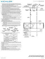
GREEN GROUND
SCREW
CUPPED
WASHER
OUTLET BOX
GROUND
FIXTURE
GROUND
DIMPLES
WIRE CONNECTOR
OUTLET BOX
GROUND
GREEN GROUND
SCREW
FIXTURE
GROUND
A
B
Connect Black or
Red Supply Wire to:
Connect
White Supply Wire to:
Black White
*Parallel cord (round & smooth) *Parallel cord (square & ridged)
Clear, Brown, Gold or Black
without tracer
Clear, Brown, Gold or Black
with tracer
Insulated wire (other than green)
with copper conductor
Insulated wire (other than green)
with silver conductor
*Note: When parallel wires (SPT I & SPT II)
are used. The neutral wire is square shaped
or ridged and the other wire will be round in
shape or smooth (see illus.)
Neutral Wire
STEM(S)
SHORT THREADED PIPE
CAP
►
GLASS
SOCKET
SWIVEL
STEEL WASHER
NEOPRENE WASHER
MOUNTING SCREWS
OUTLET BOX
WIRE
CONNECTORS
STRAP MOUNTING
SCREWS
MOUNTING STRAP
CANOPY
LOCK-UP KNOBS
LOCKWASHERS
LOOP
CHAIN LINK
HEXNUT
LOCKWASHER
THREADED PIPE
LOOP/CHAIN LINK
►
THREADED PIPE
LOCK-UP KNOBS
LOCKWASHERS
STEM(S)
OUTLET BOX
WIRE
CONNECTORS
STRAP MOUNTING
SCREWS
HEXNUT
LOCKWASHER
RIGID STEM MOUNT
CAUTION – RISK OF SHOCK – DISCONNECT POWER AT
THE MAIN CIRCUIT BREAKER PANEL OR MAIN FUSE BOX
BEFORE STARTING AND DURING THE INSTALLATION.
LOOP/CHAIN LINK INSTALLATION
1) Insert steel washer all the way into the slot on the swivel.
2) Slip the flexible washer onto the steel washer.
3) Pass the fixture wire up through the glass and out through the
top.
4) Pass the fixture wire through the cap and out the narrow end.
5) Pass wire through a stem on the end with a short threaded
pipe.
6) Raise the socket into the glass. Rest the inside of the top of
the glass onto the washers.
7) Rest the cap onto the top of the glass.
8) Screw the stem to swivel on top of fixture body (inside the
cap). NOTE: Thread locking compound must be applied to all
stem threads as noted with symbol () to prevent accidental
rotation of fixture during cleaning, relamping, etc.
9) Pass wire through stem and screw stem to coupling on top of
fixture body. NOTE: Thread locking compound must be applied
to all stem threads as noted with arrow symbol to prevent
accidental rotation of fixture during cleaning, relamping, etc.
10) Pass wire through remaining stems and screw stems together.
11) Pass fixture wire through first loop. Thread first loop onto end
of last stem.
12) Pass threaded pipe at end of second loop through hole in
canopy. Thread lockwasher onto threaded pipe protruding from
inside canopy. Pass fixture wire through hole in hexnut and
thread hexnut onto end of threaded pipe.
13) Attach chain link to small loop at end of stem and to loop on
canopy. Close chain link ends together using chain pliers or
padded pliers to prevent damage to finish.
14) Find the appropriate threaded holes on mounting strap.
Assemble mounting screws into threaded holes.
15) Attach mounting strap to outlet box.
Mounting strap can be adjusted to suit position of fixture.
16) Grounding instructions: (See Illus. A or B).
A) On fixtures where mounting strap is provided with a hole
and two raise dimples. Wrap ground wire from outlet box
around green ground screw, and thread into hole.
B) On fixtures where a cupped washer is provided. Put ground
wire from outlet box under cupped washer and green
ground screw and thread screw into hole in mounting strap.
If fixture is provided with ground wire. Connect fixture
ground wire to outlet box ground wire with wire connector,
(not provided) after following the above steps. Never con-
nect ground wire to black or white power supply wires.
17) Make wire connections. Reference chart below for correct
connections and wire accordingly.
18) Push fixture to ceiling, carefully passing mounting screws
through holes in canopy. NOTE: Be certain wires do not get
pinched between mounting plate and canopy.
19) Slip lockwashers over mounting screws. Thread lock-up
knobs onto mounting screws. Tighten lock-up knobs to
secure fixture to ceiling.
20) Insert recommended bulb (Not supplied).
RIGID STEM INSTALLATION
1) Follow steps 1-9 from “Loop/Chain Link Installation”.
2) Make sure last stem has small threaded pipe attached.
3) Remove hexut, lockwasher, and loop from canopy.
4) Pass fixture wire through hole in canopy. Pass hole in canopy
down over threaded pipe on top of fixture body.
5) Pass lockwasher onto threaded pipe protruding from inside
of canopy and screw hexnut onto threaded pipe. Tighten to
secure.
6) Follow steps 14-20 from “Loop/Chain Link Installation”.

Date Issued: 02/16/17
IS-43953-US
We’re here to help 866-558-5706
Hrs: M-F 9am to 5pm EST
INSTALACIÓN CON ANILLO/ESLABÓN DE CADENA
1) Inserte completamente la arandela de acero en la ranura en la unión girato
ria.
2) Deslice la arandela flexible en la arandela de acero.
3) Pase el cable del artefacto hacia arriba a través del vidrio y hacia afuera a
través de la parte superior.
4) Pase el cable del artefacto a través de la tapa y saliendo por el extremo
estrecho.
5) Pase el cable a través de un vástago en el extremo con un tubo roscado
corto.
6) Suba el portalámparas hacia el vidrio. Coloque el interior de la parte superi
or del vidrio en las arandelas.
7) Coloque la tapa en la parte superior del vidrio.
8) Enrosque el vástago a la unión giratoria en la parte superior del cuerpo del
artefacto (dentro de la tapa). NOTA: Se debe aplicar el compuesto para
rosca estanca a todas las roscas de vástagos indicadas con el símbolo (►)
para evitar la rotación accidental del artefacto durante su limpieza, cambio
de bombillas, etc.
9) Pase el cable a través del vástago y enrosque el vástago al acoplamiento
en la parte superior del cuerpo del artefacto. NOTA: Se debe aplicar el
compuesto para rosca estanca a todas las roscas de vástagos indicadas
con el símbolo para evitar la rotación accidental del artefacto durante su
limpieza, cambio de bombillas, etc.
10)) Pase el cable a través de los vástagos restantes y enrósquelos juntos.
11) Pase el cable del artefacto a través del primer anillo. Enrosque el primer
anillo en el extremo del último vástago.
12) Pase el tubo roscado en el extremo del segundo anillo a través del agujero
en el escudete. Enrosque la arandela de seguridad en el tubo roscado que
sobresale del interior del escudete. Pase el cable del artefacto a través del
agujero en la tuerca hexagonal y enrosque la tuerca hexagonal en el ex
tremo del tubo roscado.
13) Fije el eslabón de la cadena al anillo pequeño en el extremo del vástago y al
anillo en el escudete. (Cierre los extremos de los eslabones de cadena,
usando pinza para cadena o pinza acolchada para evitar daño al acabado).
14) Localice los agujeros roscados apropiados en la abrazadera de montaje.
Coloque los tornillos de montaje en los agujeros roscados.
15) Fije la abrazadera de montaje a la caja de salida.
La abrazadera de montaje puede ser ajustada para acomodarse a la
posición del artefacto.
ARANDELA
CONCAVA
TIERRA DE LA
CAJA DE SALIDA
TORNILLO DE TIERRA,
VERDE
DEPRESIONES
TIERRA
ARTEFACTO
CONECTOR DE ALAMBRE
TIERRA DE LA
CAJA DE SALIDA
TORNILLO DE TIERRA,
VERDE
TIERRA
ARTEFACTO
A
B
Conectar el alambre de
suministro negro o rojo al
Conectar el alambre de
suministro blanco al
Negro Blanco
*Cordon paralelo (redondo y liso)
*Cordon paralelo (cuadrado y estriado)
Claro, marrón, amarillio o negro
sin hebra identificadora
Claro, marrón, amarillio o negro
con hebra identificadora
Alambre aislado (diferente del verde)
con conductor de cobre
Alambre aislado (diferente del
verde) con conductor de plata
*Nota: Cuando se utiliza alambre paralelo
(SPT I y SPT II). El alambre neutro es de forma
cuadrada o estriada y el otro alambre será de
forma redonda o lisa. (Vea la ilustracíón).
Hilo Neutral
PRECAUCIÓN – RIESGO DE DESCARGA ELÉCTRICA – DESCONECTE
LA ELECTRICIDAD EN EL PANEL PRINCIPAL DEL INTERRUPTOR
AUTOMÁTICO O CAJA PRINCIPAL DE FUSIBLES ANTES DE COMENZAR
Y DURANTE LA INSTALACIÓN.
16) Instrucciones para poner a tierra: (Ver Ilustraciones A o B).
A) En artefactos donde se suministra la abrazadera de montaje con un
agujero y dos depresiones onduladas: envuelva el conductor de tierra
de la caja de salida alrededor del tornillo de conexión a tierra verde y
atornille en el agujero.
B) En artefactos donde se suministra una arandela cóncava: ponga el
conductor de tierra de la caja de salida debajo de la arandela cóncava y
el tornillo de conexión a tierra verde, y atornille en el agujero en la
abrazadera de montaje. Si el artefacto se suministra con conductor de
tierra: conecte el conductor de tierra del artefacto al conductor de tierra
de la caja de salida con conector de alambre (no provisto) después de
seguir los pasos anteriores. Nunca conecte el conductor de tierra a los
cables de alimentación eléctrica negros o blancos.
17) Haga las conexiones de cables restantes usando los conectores provistos.
Consulte la gráfica de abajo con las conexiones correctas y haga el cablea
do que corresponda.
18) Empuje el artefacto a la pared, pasando cuidadosamente los tornillos de
montaje a través de los agujeros en el escudete. NOTA: Cerciórese que los
cables no queden apretados entre la placa de montaje y el escudete.
19) Deslice las arandelas de seguridad sobre los tornillos de montaje.
Enrosque las perillas de sujeción en los tornillos de montaje. Apriete las
perillas para asegurar el artefacto al techo.
20) Inserte la bombilla recomendada. (No se provee).
INSTALACIÓN CON VÁSTAGO RÍGIDO
1) Siga los pasos 1-9 de “Instalación con Anillo/Eslabón de Cadena”.
2) Asegúrese de que el último vástago tenga el tubo roscado pequeño fijado
a él.
3) Remueva la tuerca hexagonal, la arandela de seguridad y el anillo del escu
dete.
4) Pase el cable del artefacto a través del agujero en el escudete. Pase el
agujero en el escudete hacia abajo sobre el tubo roscado encima del cuer
po del artefacto.
5) Pase la arandela de seguridad sobre el tubo roscado que sobresale del
interior del escudete y enrosque la tuerca hexagonal en el tubo roscado.
Apriete para asegurar.
6) Siga los pasos 14-20 de “Instalación con Anillo/Eslabón
VÁSTAGO
TUBO ROSCADO
TAPA
►
VIDRIO
PORTALÁMPARAS
UNIÓN GIRATORIA
ARANDELA DE ACERO
ARANDELA DE NEOPRENO
TORNILLO DE MONTAJE
CAJA DE SALIDA
CONECTORES DE ALAMBRE
TORNILLOS DE MONTAJE
DE LA ABRAZADERA
ABRAZADERA DE MONTAJE
ESCUDETE
PERILLAS DE SUJECIÓN
ARANDELA DE SEGURIDAD
ANILLO
ESLABÓN DE CADENA
TUERCA HEXAGONAL
ARANDELA DE SEGURIDAD
TUBO ROSCADO
ANILLO/ESLABÓN DE CADENA
►
TUBO ROSCADO
ARANDELA
DE SEGURIDAD
PERILLAS
DE SUJECIÓN
VÁSTAGO
TUERCA HEXAGONAL
ARANDELA DE SEGURIDAD
MONTAJE DEL VÁSTAGO RIGIDO
CONECTORES DE ALAMBRE
CAJA DE SALIDA
TORNILLOS DE MONTAJE
DE LA ABRAZADERA
/