
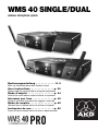
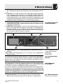
WMS 40 SINGLE/DUAL
wireless microphone system
Bedienungsanleitung . . . . . . . . . . . . S. 2
Bitte vor Inbetriebnahme des Gerätes lesen!
User Instructions . . . . . . . . . . . . . . p. 20
Please read the manual before using the equipment!
Mode d’emploi . . . . . . . . . . . . . . . . p. 34
Veuillez lire cette notice avant d’utiliser le système!
Istruzioni per l’uso . . . . . . . . . . . . . p. 49
Prima di utilizzare l’apparecchio, leggere il manuale
Modo de empleo . . . . . . . . . . . . . . . p. 65
¡Sirvase leer el manual antes de utilizar el equipo!
Instruções de uso
. . . . . . . . . . . . . .
p. 80
Favor leia este manual antes de usar o equipamen
to!
Page is loading ...
Page is loading ...
Page is loading ...
Page is loading ...
Page is loading ...
Page is loading ...
Page is loading ...
Page is loading ...
Page is loading ...
Page is loading ...
Page is loading ...
Page is loading ...
Page is loading ...
Page is loading ...
Page is loading ...
Page is loading ...
Page is loading ...
Page is loading ...

Table of Contents
WMS 40 SINGLE/DUAL
20
Page
Figs. 3, 4, 8, 9.........................................................................................2
Figs. 5, 6, 7, 10.......................................................................................3
Figs. 11 through 16................................................................................4
FCC Statement....................................................................................21
1 Safety and Environment ................................................................21
1.1 Safety .......................................................................................21
1.2 Environment .............................................................................22
2 Description .....................................................................................22
2.1 Introduction..............................................................................22
2.2 Unpacking ................................................................................22
2.3 Optional Accessories ...............................................................23
2.4 SR 40 SINGLE/DUAL Receivers ..............................................23
2.4.1 Front Panel Controls .......................................................23
2.4.2 Rear Panel Controls ........................................................24
2.4.3 Automatic Squelch..........................................................24
2.5 HT 40 PRO Handheld Transmitter............................................25
2.5.1 Controls...........................................................................25
2.6 PT 40 PRO Bodypack Transmitter ...........................................25
2.6.1 Controls...........................................................................25
2.6.2 Microphones, Guitar Cable .............................................26
3 Setting Up.......................................................................................27
3.1 Positioning the Receiver ..........................................................27
3.2 Connecting the Receiver to a Balanced Input .........................27
3.3 Connecting the Receiver to an Unbalanced Input ...................27
3.4 Connecting the Receiver to Power ..........................................27
3.5 Inserting and Testing Batteries in the Handheld/
Bodypack Transmitters ............................................................28
3.6 Setting Up the Handheld Transmitter.......................................28
3.6.1 Replacing the Color Code Clip .......................................28
3.7 Setting Up the Bodypack Transmitter ......................................28
3.7.1 Connecting a Microphone...............................................29
3.7.2 Connecting an Instrument...............................................29
3.7.3 Inserting a Label..............................................................29
3.8 Before the Soundcheck............................................................29
4 Microphone Technique..................................................................30
4.1 HT 40 PRO Handheld Transmitter............................................30
4.1.1 Working Distance and Proximity Effect...........................30
4.1.2 Angle of Incidence...........................................................30
4.1.3 Feedback ........................................................................30
4.1.4 Backing Vocals................................................................30
4.2 CK 55 L Lavalier Microphone...................................................30
4.3 C 444 L Head-worn Microphone..............................................31
4.3.1 Putting On the Microphone.............................................31
4.3.2 Windscreen .....................................................................31
4.3.3 Moisture Shield ...............................................................31
5
Cleaning
..........................................................................................
31
5.1 Surfaces ...................................................................................31
5.2 Handheld Transmitter Internal Windscreen..............................31
6
T
r
oubleshooting
.............................................................................
32
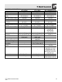
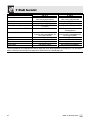
7 Specifications.................................................................................33
7.1 WMS 40 SINGLE/DUAL ...........................................................33
7.2 CK 55 L, C 444 L......................................................................33

1 Safety and Environment
21WMS 40 SINGLE/DUAL
1.1 Safety1. Do not spill any liquids on the equipment and do not drop any objects
through the ventilation slots in the equipment.
2. The equipment may be used in dry rooms only.
3. The equipment may be opened, serviced, and repaired by authorized
personnel only. The equipment contains no user-serviceable parts.
4. Before connecting the equipment to power, check that the AC mains
voltage stated on the supplied AC adapter is identical to the AC mains
voltage available where you will use the equipment.
5. Operate the equipment with the supplied AC adapter with a 12-VDC
output. Using adapters with a different output voltage or current type
may cause serious damage to the unit.
6. If any solid object or liquid penetrates into the equipment, shut down
the sound system immediately. Disconnect the AC adapter from the
power outlet immediately and have the equipment checked by AKG
service personnel.
7. If you will not use the equipment for a long period of time, disconnect
the AC adapter from the power outlet. Please note that the equipment
will not be fully isolated from power when you set the power switch
to OFF.
8. Do not place the equipment near heat sources such as radiators, heat-
ing ducts, or amplifiers, etc. and do not expose it to direct sunlight,
excessive dust, moisture, rain, mechanical vibrations, or shock.
9. To avoid hum or interference, route all audio lines, particularly those
connected to the microphone inputs, away from power lines of any type.
If you use cable ducts, be sure to use separate ducts for the audio lines.
10.Clean the equipment with a moistened (not wet) cloth only. Be sure to
disconnect the AC adapter from the power outlet before cleaning the
equipment! Never use caustic or scouring cleaners or cleaning agents
containing alcohol or solvents since these may damage the enamel and
plastic parts.
11.Use the equipment for the applications described in this manual only.
AKG cannot accept any liability for damages resulting from improper
handling or misuse.
F
CC Statement
T
his equipment has been tested and found to comply with the limits for a Class B digital device, pursuant to Parts 74
a
nd 15 of the FCC Rules. These limits are designed to provide reasonable protection against harmful interference in a
r
esidential installation. This equipment generates, uses, and can radiate radio frequency energy and, if not installed and
u
sed in accordance with the instructions, may cause harmful interference to radio communications. However, there is
no guarantee that interference will not occur in a particular installation. If this equipment does cause harmful interfer-
ence to radio or television reception, which can be determined by turning the equipment off and on, the user is encouraged
to try to correct the interference by one or more of the following measures:
•
Reorient or relocate the receiving antenna.
• I
ncrease the separation between the equipment and the receiver.
• C
onnect the equipment into an outlet on a circuit different from that to which the receiver is connected.
•
Consult the dealer or an experienced radio/TV technician for help.
Shielded cables and I/O cords must be used for this equipment to comply with the relevant FCC regulations.
Changes or modifications not expressly approved in writing by AKG Acoustics may void the user’s authority to operate
this equipment.
This device complies with Part 15 of the FCC Rules. Operation is subject to the following two conditions: (1) this device
may not cause harmful interference, and (2) this device must accept any interference received, including interference
that may cause undesired operation.

1 Safety and Environment
WMS 40 SINGLE/DUAL
22
1.2 Environment
2.1 Introduction
2.2 Unpacking
Kits with SR 40
SINGLE receiver
1. The AC adapter will draw a small amount of current even when the
equipment is switched off. To save energy, disconnect the AC adapter
from the power outlet if you will leave the equipment unused for a long
period of time.
2. When scrapping the equipment, separate the case, circuit boards, and
cables, and dispose of all components in accordance with local
waste disposal rules.
3. The packaging of the equipment is recyclabe. Dispose of the pack-
aging in an appropriate container provided by the local waste collec-
tion/recycling entity and observe all local legislation relating to waste
disposal and recycling.
Thank you for purchasing an AKG product. This Manual contains impor-
tant instructions for setting up and operating your equipment. Please take
a few minutes to read the instructions below carefully before operat-
ing the equipment. Please keep the Manual for future reference. Have
fun and impress your audience!
The WMS 40 SINGEL/DUAL is available in four kits with an SR 40 SIN-
GLE single-channel receiver and four kits with an SR 40 DUAL dual-chan-
nel receiver:
2 Description
INSTRUMENTAL SET SINGLE
1 PT 40 PRO bodypack trans-
mitter
1 AA size battery
1 set of lettering labels
1 MKG L guitar cable
1 SR 40 SINGLE receiver
1 AC adapter (see sticker on
packaging)
1 Manual Supplement sheet
PRESENTER SET SINGLE
1 PT 40 PRO bodypack trans-
mitter
1 AA size battery
1 set of lettering labels
1 CK 55 L lavalier microphone
with attachment clip
1
W 55 windscreen
1
SR 40 SINGLE receiver
1 AC adapter (see sticker on
packaging)
1 Manual Supplement sheet
SPORTS SET SINGLE
1 PT 40 PRO bodypack trans-
mitter
1 AA size battery
1 set of lettering labels
1 C 444 L head-worn micro-
phone
2 moisture shields
1 W 444 windscreen
1 SR 40 SINGLE receiver
1 AC adapter (see sticker on
packaging)
1 Manual Supplement sheet
VOCAL SET SINGLE
1 HT 40 PRO handheld trans-
mitter
1 stand adapter
1
AA size battery
1
semitransparent replacement
clip
1 SR 40 SINGLE receiver
1 AC adapter (see sticker on
packaging)
1 Manual Supplement sheet

2 Description
23WMS 40 SINGLE/DUAL
Kits with SR 40
DUAL receiver
2.3 Optional
Accessories
2.4 SR 40
SINGLE/DUAL
Receivers
2.4.1 Front Panel
Controls
Check that the packaging contains all of the items listed for your system.
Should any item be missing, please contact your AKG dealer.
RMU 40 PRO 19" rack mounting kit for two SR 40 SINGLE or DUAL receivers
W 880 foam windscreen for HT 40 PRO
The SR 40 SINGLE/DUAL series includes two stationary non-diversity re-
ceivers for use with all WMS 40 SINGLE/DUAL and Microtools Series trans-
mitters. They feature a half-rack case for mounting in a 19" rack.
The SR 40 SINGLE provides a single reception channel and operates on
one fixed, quartz stabilized frequency in the 710 MHz to 865 MHz UHF
carrier frequency range.
The SR 40 DUAL combines two SR 40 SINGLE receiver channels in one
half-rack case. Each channel operates on a separate frequency.
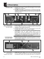
1 ON/OFF: On/off pushbutton switch with status LED.
2 Antenna (1 per channel): Fixed-length UHF antenna permanently
mounted on the front panel.
3 VOLUME (1 per channel): This rotary control adjusts the receiver’s out-
put level from microphone to line level for matching to the input sen-
sitivity of your mixer or amplifier.
GUITAR/VOCAL SET DUAL
1 PT 40 PRO bodypack trans-
mitter
1 AA size battery
1 set of lettering labels
1 C 444 L head-worn micro-
phone
2 moisture shields
1 W 444 windscreen
1 GB 40 Guitarbug with user
manual
1 AAA size battery
1 adapter plug
1 SR 40 DUAL receiver
1 AC adapter (see sticker on
packaging)
1 Manual Supplement sheet
INSTRUMENTAL SET DUAL
2 PT 40 bodypack transmitters
2 AA size batteries
1 set of lettering labels
2 MKG L guitar cables
1 SR 40 DUAL receiver
1 AC adapter (see sticker on
packaging)
1 Manual Supplement sheet
PRESENTER SET DUAL
1 HT 40 handheld transmitter
1 stand adapter
1 semitransparent replacement
clip
1 PT 40 PRO bodypack trans-
mitter
2 AA size batteries
1 set of lettering labels
1 C 444 L head-worn micro-
phone
2 moisture shields
1 W 444 windscreen
1 SR 40 DUAL receiver
1 AC adapter (see sticker on
packaging)
1 Manual Supplement sheet
VOCAL SET DUAL
2 HT 40 handheld transmitters
2 stand adapters
2 AA size batteries
2 semitransparent replacement
clips
1 SR 40 DUAL receiver
1 AC adapter (see sticker on
packaging)
1 Manual Supplement sheet

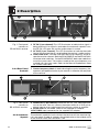
2 Description
WMS 40 SINGLE/DUAL
24
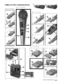
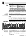
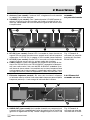
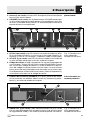
Fig. 1: Front panel
controls on
SR 40 DUAL receiver
2.4.2 Rear Panel
Controls
Fig. 2: Rear panel
controls on
SR 40 DUAL receiver.
2.4.3 Automatic
Squelch
4 RF OK (1 per channel): This LED illuminates to indicate that signal is
being received. If no signal is received or the automatic squelch is on,
the RF OK LED goes out and the audio output is muted.
5 AF CLIP (1 per channel): This LED illuminates to indicate the audio
level of the received signal is overloading the receiver's audio section.
6 Color code lines: The color indicates the carrier frequency of the re-
spective receiver channel. Both the SR 40 SINGLE and the SR 40 DUAL
have two color code lines. On the SR 40 SINGLE, both color code lines
are of the same color. Transmitters tuned to the same frequency are
marked with the same color. Refer to the Manual Supplement sheet
for a color code table.
7 Carrier frequency label: A label indicating the carrier frequency (fre-
quencies) and approval marks of your receiver is affixed to the rear panel
of the receiver.
8 AUDIO OUT (1 per channel): Balanced TRS 1/4" jack, adjustable from
mic to line level. You can connect the output either to an XLR micro-
phone input or to an unbalanced line input on a mixer or amplifier.
9
Strain r
elief
for the feeder cable of the supplied AC adapter
.
10
DC ONL
Y:
Input connector for the supplied AC adapter
.
The automatic squelch cir
cuit switches the r
eceiver of
f if the r
eceived sig-
nal is too weak, in or
der to suppr
ess the r
elated noise or the r
esidual noise
of the r
eceiver while the transmitter is of
f.
22
13 6 36
4 455
7 9
10
8
8

2 Description
25WMS 40 SINGLE/DUAL
2.5 HT 40 PRO
Handheld Transmitter
2.5.1 Controls
Refer to fig. 3 on page 2.
Note:
2.6 PT 40 PRO Body-
pack Transmitter
2.6.1 Controls
Refer to fig. 4 on page 2.
Note:
The HT 40 PRO handheld transmitter operates on a single fixed, quartz sta-
bilized frequency in the 710 MHz to 865 MHz UHF carrier frequency range
and uses an antenna integrated in the body.
The microphone element permanently mounted on the transmitter uses
a high quality cardioid transducer from AKG. It provides low handling noise
sensitivity, high gain before feedback, and brilliant sound quality, as well
as a built-in wind and pop filter to reduce wind and breath noise.
11 On/off switch: This slide switch provides three positions indicated in
the display window:
ON: Power to the transmitter is on.
MUTE: The signal delivered by the microphone element is muted while
power and the RF carrier frequency remain on.
OFF: Power to the transmitter is off.
12 Status LED: Indicates the transmitter's operating status.
LED lit green: Battery is OK.
LED lit red: From the moment the LED changes to red, the battery ca-
pacity will provide a maximum of two operating hours. We recommend
replacing the battery with a new one as soon as possible.
If you use a rechargeable battery, the LED will change to red 15 min-
utes before the battery will be dead!
13 Color code clip: The color of this plastic clip indicates the carrier fre-
quency of your transmitter. Receiver channels tuned to the same fre-
quency are marked with the same color. Refer to the Manual Supple-
ment sheet for a color code table.
You can remove the color code clip on the HT 40 PRO and replace it
with the supplied semitransparent clip.
14 Battery compartment lid: Refer to section 3.5.
15 Carrier frequency label: The label above the battery compartment in-
dicates the carrier frequency and approval marks of your transmitter.
You can use the PT 40 PRO bodypack transmitter with both dynamic mi-
crophones and condenser microphones operating on a supply voltage of
approx. 4 V. You may also connect an electric guitar, electric bass, or re-
mote keyboard.
The PT 40 PRO operates on a single fixed, quartz stabilized frequency in
the 710 MHz to 865 MHz UHF carrier frequency range.
16 On/off switch: This slide switch provides three positions indicated in
the display window:
ON: Power to the transmitter is on.
MUTE: The signal delivered by the microphone element is muted while
power and the RF carrier frequency remain on.
OFF: Power to the transmitter is off.
17 Status LED: Indicates the transmitter's operating status.
LED lit green: Battery is OK.
LED lit red: From the moment the LED changes to red, the battery ca-
pacity will provide a maximum of two operating hours. We recommend
replacing the battery with a new one as soon as possible.
If you use a rechargeable battery, the LED will change to red 15 min-
utes before the battery will be dead!

2 Description
WMS 40 SINGLE/DUAL
26
Note:
2.6.2 Microphones,
Guitar Cable
18 Audio input: 3-pin mini XLR connector with both mic and line level pins
that automatically match the connector pinout of the recommended
AKG microphones or optional MKG L guitar cable.
While the MKG L guitar cable is included in some WMS 40 SINGLE/
DUAL kits (see section 2.2 Unpacking), it is also available as an op-
tional accessory.
19 Antenna: Permanently connected, flexible antenna.
20 Belt clip for fixing the transmitter to your belt.
21 Battery compartment lid with integrated screwdriver (21a).
21b Viewing window: The viewing window lets you check if there is a dry
or rechargeable battery inside the battery compartment. You can also
insert a white lettering strip (supplied) or a color code strip (optional)
into the viewing window.
22 GAIN: This rotary control inside the battery compartment allows you
to match the bodypack transmitter input gain to the microphone or in-
strument you connected to the transmitter.
23 Carrier frequency label: The label on the transmitter rear panel indi-
cates the carrier frequency, color code (receiver channels with the same
carrier frequency are marked with the same color), and approval marks
of your transmitter. Refer to the Manual Supplement sheet for a color
code table.
The PT 40 PRO has been designed specifically for use with the following
AKG microphones:
CK 55 L
C 417 L
C 420 L
C 444 L
The MKG L guitar cable from AKG lets you connect an electric guitar, elec-
tric bass, or remote keyboard to the bodypack transmitter. One or two MKG
L guitar cables, respectively, are included in the Instrumental Set Single
and Instrumental Set Dual. The MKG L guitar cable is also available sep-
arately as an accessory.

3 Setting Up
27WMS 40 SINGLE/DUAL
Important!
3.1 Positioning the
Receiver
3.2 Connecting the
Receiver to a
Balanced Input
Refer to fig. 5 on page 3.
3.3 Connecting the
Receiver to an Un-
balanced Input
Refer to fig. 6 on page 3.
Important!
3.4 Connecting the
Receiver to Power
Refer to fig. 7 on page 3.
Prior to setting up your WMS 40 SINGLE/DUAL, check that the
transmitter and receiver are tuned to the same frequency. The eas-
iest way to do this is to compare the color codes on the transmitter
and receiver.
• You can either use the receiver freestanding or mount it in a 19" rack
using the optional RMU 40 PRO rack mounting kit. For instructions on
how to rack mount the receiver, refer to the RMU 40 PRO manual.
• Reflections off metal parts, walls, ceilings, etc. or the shadow effects
of musicians and other people may weaken or cancel the direct trans-
mitter signal.
For best results, place the receiver as follows:
1. Place the receiver near the performance area (stage). Make sure,
though, that the transmitter will never get any closer to the receiver
than 10 ft (3 m). Optimum separation is 16 ft. (5 m).
2. Check that you can see the receiver from where you will be using
the transmitter.
3. Place the receiver at least 5 ft. (1.5 m) away from any big metal ob-
jects, walls, scaffolding, ceilings, etc.
1. For each channel, use a balanced cable with an XLR connector and
1/4" TRS jack plug (available from electronics or hi-fi stores).
2. Connect the (each) AUDIO OUT jack (8) on the receiver rear panel to
the desired balanced (XLR) microphone input on the mixer or ampli-
fier.
3. Turn the (two) VOLUME control(s) (3) on the receiver all the way CCW
to set the receiver output to mic level.
1. Use a standard 1/4" jack cable to connect the (each) AUDIO OUT jack
(8) on the receiver rear panel to an unbalanced 1/4" line input jack on
the mixer or amplifier.
2. Turn the (two) VOLUME control(s) (3) on the receiver all the way CW to set
the receiver output to line level.
To avoid hum interference, do not use audio cables longer than 10
feet (3 m)!
1. Check that the AC mains voltage stated on the included power sup-
ply is identical to the AC mains voltage available where you will
use your system. Using the power supply with a different AC volt-
age may cause damage to the unit.
2. Point the antenna(s) (2) upward.
3. Plug the feeder cable on the included power supply into the DC ONLY
socket (10) on the receiver.
4. Bend part of the feeder cable into a small bight, pass the bight through
the strain relief (9) from above, and slip the bight over the hook on the
strain relief (9). Tighten the cable.
5. Plug the AC adapter into a convenient power outlet.
6. Press the ON/OFF switch (1) to switch power to the receiver ON.

3 Setting Up
WMS 40 SINGLE/DUAL
28
3.5 Inserting and
Testing Batteries in
the Handheld/Body-
pack Transmitters
Refer to fig. 8 on page 2.
Note:
3.6 Setting Up the
Handheld Transmitter
Also refer to section 4
Microphone Technique.
3.6.1 Replacing the
Color Code Clip
Refer to fig. 9 on page 2.
3.7 Setting Up the
Bodypack Transmitter
1. Depress the snap hook on the battery compartment lid (14)/(21).
2. Pull the battery compartment lid (14)/(21) off the transmitter in the di-
rection of the arrow.
3. Insert the supplied battery into the battery compartment conforming
to the polarity marks.
The transmitter will not function if you insert the battery the other way
round.
4. Set the on/off switch (11)/(16) to "ON" to switch power to the trans-
mitter on.
If the battery is in good condition, the status LED (12)/(17) will be lit
green.
If the status LED (12)/(17) is lit red, the battery will be dead within about
two hours. Replace the battery with a new one as soon as possible.
If you use a rechargeable battery, the LED will switch to red 15 min-
utes before the battery will be dead!
If the status LED (12)/(17) fails to illuminate the battery is dead. Insert
a new battery.
5. To close the battery compartment, slide the battery compartment lid
(14)/(21) onto the battery compartment from below to the point that
the snap hook will engage.
1. Switch power to the receiver on.
2. To switch power to the transmitter on, set the on/off switch (11) to "ON".
Since the HT 40 PRO handheld transmitter has been designed specif-
ically for the integrated microphone element, there is no need to set
gain on the handheld transmitter. Therefore, the handheld transmitter
has no level or gain control.
3. Switch power to your sound system or amplifier on.
4. Talk or sing into the microphone and set the levels on your mixer or
amplifier referring to the appropriate instruction manual, or by ear.
1. Pull the color code clip (13) off the transmitter case in the direction of
the arrow.
2. Slide the supplied semitransparent replacement clip onto the trans-
mitter to the point that it snaps into place with an audible click.
The PT 40 PRO bodypack transmitter has been designed for use with the
CK 55 L, C 417 L, C 420 L, and C 444 L microphones from AKG. If you
wish to connect other microphones from AKG or other manufacturers to
the PT 40 PRO, please note that you may have to rewire the existing con-
nector of your microphone or replace it with a 3-pin mini XLR connector.
Audio input (18) pinout:
Pin 1: shield
Pin 2: audio inphase (+)
Pin 3: supply voltage
A 4-V positive supply voltage for condenser microphones is available on
pin 3.

3 Setting Up
29WMS 40 SINGLE/DUAL
Important
3.7.1 Connecting a
Microphone
Refer to fig. 10 on
page 3.
Also refer to section 4
Microphone Technique.
3.7.2 Connecting an
Instrument
Refer to fig. 10 on
page 3.
3.7.3 Inserting a
Label
3.8 Before the
Soundcheck
Please note that AKG cannot guarantee that the PT 40 PRO bodypack
transmitter will work perfectly with products from other manufacturers
and any damage that may result from such use is not covered by the
AKG warranty scheme.
1. Remove the battery compartment lid (21).
2. Plug the mini XLR connector on the cable of your microphone into the
audio input socket (18) on the bodypack transmitter.
3. Set the on/off switch (16) to "ON" to switch power to the bodypack
transmitter on.
4. Switch power to the receiver on.
5. Talk or sing into the microphone.
6. Use the screwdriver (21a) integrated in the battery compartment lid (21)
to set the GAIN control (22) to a position where the AF CLIP LED (5)
on the receiver will flash occasionally.
7. Replace the battery compartment lid (21) on the transmitter.
1. Remove the battery compartment lid (21).
2. Plug the jack plug on the MKG L guitar cable into the output jack on
your instrument and the mini XLR connector on the guitar cable into
the audio input socket (18) on the bodypack transmitter.
3. Set the on/off switch (16) to "ON" to switch power to the bodypack
transmitter on.
4. Switch power to the receiver on.
5. Play your instrument.
6. Use the screwdriver (21a) integrated in the battery compartment lid (21)
to set the GAIN control (22) to a position where the AF CLIP LED (5)
on the receiver will flash occasionally.
7. Replace the battery compartment lid (21) on the transmitter.
1. Remove the battery compartment lid (21).
2. Remove a label from the supplied sheet.
3. Letter the label as desired.
4. Remove the battery and place the label on the viewing window (21b).
5. Replace the battery and slide the compartment lid (21) back in place
on the transmitter.
1. Move the transmitter around the area where you will use the system
to check the area for "dead spots", i.e., places where the field strength
seems to drop and reception deteriorates.
If you find any dead spots, try to eliminate them by repositioning the
receiver. If this does not help, avoid the dead spots.
2. The RF OK LED (4) on the receiver going out means no signal is be-
ing received or the automatic squelch is active.
Switch power to the transmitter ON or move closer to the receiver, to
the point that the RF OK LED (4) will come back on.

4 Microphon Technique
WMS 40 SINGLE/DUAL
30
4.1 HT 40 PRO
Handheld Transmitter
4.1.1 Working
Distance and
Proximity Effect
4.1.2 Angle of
Incidence
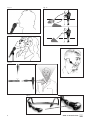
Refer to fig. 11 on
page 4.
4.1.3 Feedback
Refer to fig. 12a on
page 4.
Refer to fig. 12b on
page 4.
4.1.4 Backing Vocals
Refer to fig. 13 on
page 4.
4.2 CK 55 L Lavalier
Microphone
Refer to fig. 14 on
page 4.
A handheld vocal microphone provides many ways of shaping the sound
of your voice as it is heard over the sound system.
The following sections contain useful hints on how to use your HT 40 PRO
handheld transmitter for best results.
Basically, your voice will sound the bigger and mellower, the closer you
hold the microphone to your lips. Moving away from the microphone will
produce a more reverberant, more distant sound as the microphone will
pick more of the room’s reverberation.
You can use this effect to make your voice sound aggressive, neutral, in-
sinuating, etc. simply by changing your working distance.
Proximity effect is a more or less dramatic boost of low frequencies that
occurs when you sing into the microphone from less than 2 inches. It gives
more "body" to your voice and an intimate, bass-heavy sound.
Sing to one side of the microphone or above and across the microphone’s
top. This provides a well-balanced, natural sound.
If you sing directly into the microphone, it will not only pick up excessive
breath noise but also overemphasize "sss", "sh", "tch", "p", and "t" sounds.
Feedback is the result of part of the sound projected by a speaker being
picked up by a microphone, fed to the amplifier, and projected again by
the speaker. Above a specific volume or "system gain" setting called the
feedback threshold, the signal starts being regenerated indefinitely, mak-
ing the sound system howl and the sound engineer desperately dive for
the master fader to reduce the volume and stop the howling.
To increase usable gain before feedback, the microphone element of the
HT 40 PRO handheld transmitter has a cardioid polar pattern. This
means that the microphone is most sensitive to sounds arriving from in
front of it (your voice) while picking up much less of sounds arriving from
the sides or rear (from monitor speakers for instance).
To maximize gain before feedback, place the main (aka "FOH" - front of
house) speakers in front of the microphones (along the front edge of the
stage).
If you use monitor speakers, be sure never to point any microphone di-
rectly at the monitors, or at the FOH speakers.
Feedback may also be triggered by resonances depending on the
acoustics of the room or hall. With resonances at low frequencies, prox-
imity effect may cause feedback. In this case, it is often enough to move
away from the microphone a little to stop the feedback.
1. Never let more than two persons share a microphone.
2. Ask your backing vocalists never to sing more than 35 degrees off the
microphone axis.
The microphone is very insensitive to off-axis sounds. If the two vo-
calists were to sing into the microphone from a wider angle than 35
degrees, you may end up bringing up the fader of the microphone chan-
nel far enough to create a feedback problem.
1. Fix the microphone to the supplied lavalier clip or to the optional H 41/1
tiepin.
2. Clamp the microphone on your clothing as close as possible to the
talker's mouth.

4 Microphon Technique
31WMS 40 SINGLE/DUAL
Note:
4.3 C 444 L Head-
worn Microphone
4.3.1 Putting On the
Microphone
Refer to fig. 15 on
page 4.
Note:
4.3.2 Windscreen
4.3.3 Moisture
Shield
Refer to fig. 16 on
page 4.
5.1 Surfaces
5.2 Handheld
Transmitter Internal
Windscreen
Remember that gain-before-feedback will be the higher the closer the
microphone sits to the user's mouth!
3. Make sure to aim the microphone at the user's mouth.
1. Put the microphone on.
2. Bend the gooseneck so that the microphone will sit to one side in front
of the corner of your mouth.
• Should you hear excessive pop noise ("p" and "t" sounds are overem-
phasized unnaturally), move the microphone capsule further away from
your mouth (up or back).
• If the microphone sounds "thin" or flat, move the microphone capsule
closer to your mouth (refer to fig. 3).
• Find the optimum position during the soundcheck.
If (for instance, in outdoor use) excessive wind or pop noise becomes au-
dible, attach the supplied windscreen to the microphone.
1. Slide the windscreen onto the microphone capsule.
2. Pull the windscreen over the outer edge of the microphone capsule.
A special moisture shield on the microphone capsule makes it difficult for
moisture and makeup to penetrate into the microphone. This barrier pre-
vents the microphone sound entries from being clogged by perspiration
or makeup, which would make the sound dull and reduce the sensitivity
of the microphone. Therefore, never remove the moisture shield from the
microphone!
In case the moisture shield is damaged or lost, the C 444 L head-worn
microphone includes two replacement moisture shields.
• Use a soft cloth moistened with water to clean the receiver and trans-
mitter surfaces.
1. Unscrew the wire-mesh cap of the handheld transmitter CCW and re-
move the wire-mesh cap from the transmitter.
2. Remove the windscreen (foam sheet) from the wire-mesh cap.
3. Wash the windscreen in mild soap suds.
4. As soon as the windscreen has dried, replace it in the wire-mesh cap
and screw the wire-mesh cap onto the transmitter CW.
5 Cleaning

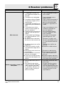
6 Troubleshooting
WMS 40 SINGLE/DUAL
32
No sound.
Noise, crackling, unwanted
signals.
Distortion.
Momentary loss of sound
("dropouts") at some
locations within
performance area.
1. AC adapter is not con-
nected to receiver and/or
power outlet.
2. Receiver is OFF.
3. Receiver is not connected
to mixer or amplifier.
4. VOLUME control on recei-
ver is at zero.
5. Microphone or instrument is
not connected to bodypack
transmitter.
6. Transmitter and receiver co-
lor codes are not identical.
7. Transmitter on/off switch is
at "OFF" or "MUTE".
8. Transmitter batteries are not
inserted properly.
9. Transmitter batteries dead.
10.Transmitter is too far away
from receiver.
11.Obstructions between
transmitter and receiver.
12.Receiver is invisible from
transmitter location.
13.Receiver is too close to me-
tal objects.
1. Antenna location.
2. Interference from other wi-
reless systems, TV, radio,
CB radios, or defective
electrical appliances or in-
stallations.
1. (Bodypack transmitter only:)
GAIN control is set too high
or too low.
2. Interference from other wi-
reless systems, TV, radio,
CB radios, or defective
electrical appliances or in-
stallations.
•
Antenna location.
1. Connect AC adapter to re-
ceiver and/or power outlet.
2. Push ON/OFF switch to
switch receiver ON.
3. Connect receiver output to
mixer or amplifier input.
4. Turn up VOLUME control.
5. Connect microphone or in-
strument to audio input on
bodypack.
6. Use receiver and transmitter
with identical color codes.
7. Set transmitter on/off switch
to "ON".
8. Insert batteries conforming
to "+" and "-" marks.
9. Replace batteries.
10.Move closer to receiver.
11.Remove obstructions.
12.Avoid spots where you can-
not see receiver.
13.Move receiver away from or
remove interfering objects.
1. Relocate receiver.
2. Switch off interference sour-
ces or defective appliances
or use a WMS 40
SINGLE/DUAL tuned to a
different frequency; have
electrical installation che-
cked.
1. Turn GAIN control down or
up just enough to stop the
distortion.
2. Switch off interference sour-
ces or defective appliances
or use a WMS 40
SINGLE/DUAL tuned to a
different frequency; have
electrical installation che-
cked.
•
Relocate r
eceiver
. If dead
spots persist, mark and
avoid them.
Problem Possible Cause Remedy

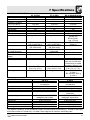
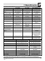
7 Specifications
33WMS 40 SINGLE/DUAL
SR 40 SINGLE/DUAL
710 to 865 MHz
FM
40 to 20,000 Hz
±15 kHz
15 kHz
typ. 0.8%
Yes
typ. 110 dB(A)
-
SR 40 SINGLE:
typ. 95 mA
SR 40 DUAL:
typ. 175 mA
120/230 VAC
50/60 Hz
-
-
-
-
-100 dBm
bal. 1/4" jack: adjustable
from mic to line level.
Output level at rated
deviation: 500 mV rms
200 x 190 x 44 mm
(7.8 x 7.4 x 1.7 in.)
SR 40 SINGLE: 580 g
(1.3 lbs.)
SR 40 DUAL: 620 g
(1.4 lbs.)
7.2 CK 55 L, C 444 L
Type
Polar pattern
Frequency range
Sensitivity
Electrical impedance at 1 kHz
Supply voltage
Cable length
Connector
Finish
Size
Net weight
CK 55 L
Pre-polarized condenser
microphone
cardioid
80 Hz to 14 kHz
0.25 mV/Pa (-72 dBV re 1 V/Pa)
1000 ohms
1.5 to 10 V from AKG WMS
bodypack transmitter
1.6 m (5 ft. 4 in.)
3-pin mini XLR
matte black
8 dia. x 22 mm (0.3 x 0.9 in.)
3 g (0.1 oz.) (w/o cable)
C 444 L
Pre-polarized condenser
microphone
cardioid
20 Hz to 20 kHz
40 mV/Pa (-28 dBV re 1 V/Pa)
200 ohms, electronically
balanced
4 to 52 V from AKG WMS
bodypack transmitter
1.5 m (5 ft.)
3-pin mini XLR
matte black
130 mm (5.1 in.) in dia.
30 g (1.1 oz.) (w/o connector)
Carrier frequency range
Modulation
Audio bandwidth
Frequency stability
(-10°C to +50°C)
Rated deviation
T.H.D. at 1 kHz
Compander
Signal/noise ratio
RF output
Current consumption
Power requirement
Battery life
Audio input level
for rated deviation
Input impedance
Condenser mic power
supply
Squelch threshold
Audio outputs
Size
Net weight
HT 40 PRO
710 to 865 MHz
FM
65 to 20,000 Hz
±15 kHz
15 kHz
typ. 0.8%
Yes
typ. 110 dB(A)
10 mW
typ. 70 mA
1 x 1.5 V AA size battery
(LR 6 to IEC 86-L)
typ. 30 hours
(for 2200 mAh)
-
-
-
-
-
229 x 53 x 53 mm
(9 x 2.1 x 2.1 in.)
160 g (5.7 oz.)
PT 40 PRO
710 to 865 MHz
FM
40 to 20,000 Hz
±15 kHz
15 kHz
typ. 0.,8%
Yes
typ. 110 dB(A)
10 mW
typ. 75 mA
1 x 1.5 V AA size battery
(LR 6 to IEC 86-L)
typ. 30 hours
(for 2200 mAh)
25 to 750 mV/1 kHz,
adjustable
1 Mohm
4 V/4.7 kohms (pin 3)
-
-
60 x 74 x 30 mm
(2.4 x 2.9 x 1.2 in.)
60 g (2.1 oz.)
7.1 WMS 40 SINGLE/DUAL
This product conforms to the standards listed in the Declaration of Conformity. To order a free copy
of the Declaration of Conformity, visit http://www.akg.com or contact [email protected].
Page is loading ...
Page is loading ...
Page is loading ...
Page is loading ...
Page is loading ...
Page is loading ...
Page is loading ...
Page is loading ...
Page is loading ...
Page is loading ...
Page is loading ...
Page is loading ...
Page is loading ...
Page is loading ...
Page is loading ...
Page is loading ...
Page is loading ...
Page is loading ...
Page is loading ...
Page is loading ...
Page is loading ...
Page is loading ...
Page is loading ...
Page is loading ...
Page is loading ...
Page is loading ...
Page is loading ...
Page is loading ...
Page is loading ...
Page is loading ...
Page is loading ...
Page is loading ...
Page is loading ...
Page is loading ...
Page is loading ...
Page is loading ...
Page is loading ...
Page is loading ...
Page is loading ...
Page is loading ...
Page is loading ...
Page is loading ...
Page is loading ...
Page is loading ...
Page is loading ...
Page is loading ...
Page is loading ...
Page is loading ...
Page is loading ...
Page is loading ...
Page is loading ...
Page is loading ...
Page is loading ...
Page is loading ...
Page is loading ...
Page is loading ...
Page is loading ...
Page is loading ...
Page is loading ...
Page is loading ...
Page is loading ...
Page is loading ...

Printed in China. 05/06/9100 U 1201
T
echnische Änderungen vorbehalten. Specifications subject to change without notice. Ces caractéristiques sont susceptibles de modifications.
Ci riserviamo il diritto di effettuare modifiche tecniche. Nos reservamos el derecho de introducir modificaciones técnicas. Especificações sujeitas à mudanças sem aviso prévio.
M
ikrofone · Kopfhörer · Drahtlosmikrofone · Drahtloskopfhörer · Kopfsprechgarnituren · Akustische Komponenten
M
icrophones · Headphones · Wireless Microphones · Wireless Headphones · Headsets · Electroacoustical Components
M
icrophones · Casques HiFi · Microphones sans fil · Casques sans fil · Micros-casques · Composants acoustiques
Microfoni · Cuffie HiFi · Microfoni senza filo · Cuffie senza filo · Cuffie-microfono · Componenti acustici
Micrófonos · Auriculares · Micrófonos inalámbricos · Auriculares inalámbricos · Auriculares con micrófono · Componentes acústicos
Microfones · Fones de ouvido · Microfones s/fios · Fones de ouvido s/fios · Microfones de cabeça · Componentes acústicos
AKG Acoustics GmbH
Lemböckgasse 21–25, P.O.B. 158, A-1230 Vienna/AUSTRIA, Tel: (+43 1) 86 654-0*, Fax: (+43 1) 86 654-7516,
www.akg.com, e-mail: [email protected], Hotline: (+43 676) 83200 888, [email protected]
AKG ACOUSTICS, U.S.
914 Airpark Center Drive, Nashville, TN 37217, U.S.A., Tel: (+1 615) 620-3800, Fax: (+1 615) 620-3875,
www.akgusa.com, e-mail: [email protected]
For other pr
oducts and distributors worldwide see our website: www
.akg.com
-
 1
1
-
 2
2
-
 3
3
-
 4
4
-
 5
5
-
 6
6
-
 7
7
-
 8
8
-
 9
9
-
 10
10
-
 11
11
-
 12
12
-
 13
13
-
 14
14
-
 15
15
-
 16
16
-
 17
17
-
 18
18
-
 19
19
-
 20
20
-
 21
21
-
 22
22
-
 23
23
-
 24
24
-
 25
25
-
 26
26
-
 27
27
-
 28
28
-
 29
29
-
 30
30
-
 31
31
-
 32
32
-
 33
33
-
 34
34
-
 35
35
-
 36
36
-
 37
37
-
 38
38
-
 39
39
-
 40
40
-
 41
41
-
 42
42
-
 43
43
-
 44
44
-
 45
45
-
 46
46
-
 47
47
-
 48
48
-
 49
49
-
 50
50
-
 51
51
-
 52
52
-
 53
53
-
 54
54
-
 55
55
-
 56
56
-
 57
57
-
 58
58
-
 59
59
-
 60
60
-
 61
61
-
 62
62
-
 63
63
-
 64
64
-
 65
65
-
 66
66
-
 67
67
-
 68
68
-
 69
69
-
 70
70
-
 71
71
-
 72
72
-
 73
73
-
 74
74
-
 75
75
-
 76
76
-
 77
77
-
 78
78
-
 79
79
-
 80
80
-
 81
81
-
 82
82
-
 83
83
-
 84
84
-
 85
85
-
 86
86
-
 87
87
-
 88
88
-
 89
89
-
 90
90
-
 91
91
-
 92
92
-
 93
93
-
 94
94
-
 95
95
-
 96
96


AKG Acoustics WMS 40 PRO User manual
- Category
- Microphones
- Type
- User manual
Ask a question and I''ll find the answer in the document
Finding information in a document is now easier with AI
in other languages
- italiano: AKG Acoustics WMS 40 PRO Manuale utente
- français: AKG Acoustics WMS 40 PRO Manuel utilisateur
- español: AKG Acoustics WMS 40 PRO Manual de usuario
- Deutsch: AKG Acoustics WMS 40 PRO Benutzerhandbuch
- português: AKG Acoustics WMS 40 PRO Manual do usuário
Related papers
-
AKG Acoustics WMS 300 User manual
-
-
-
-
-
-
-
-
-
Other documents
-
AKG WMS 40 PRO DUAL Owner's manual
-
-
-
-
-
-
-
-
-