Page is loading ...

Part Number 3604
Brochure #63-3604
©2013 Edelbrock LLC
Rev. 3/27/13 - QT/mc
1
Edelbrock EFI
Universal Return Type Fuel System
Part #3604
INSTALLATION INSTRUCTIONS
®
PLEASE study these instructions carefully before beginning the installation.
This installation may require drilling and possible
welding to the vehicle’s fuel tank or sending unit.
If you do not feel comfortable performing this installation or have never worked
with automotive fuel systems before, it is highly recommended to have the installation completed by a Professional Mechanic. If
you have any questions, please call our Technical Hotline at: 1-800-416-8628, Monday - Friday, 7:00 am - 5:00 pm, Pacific
Standard Time.
DESCRIPTION
P/N 3604 is a complete fuel system designed to work in conjunction with the Edelbrock E-Street EFI system (#3600). This system can
also be used as a stand-alone fuel system, used on other Edelbrock EFI systems, as well as other EFI systems in the market. This kit
requires the use of a “Return” type fuel pressure regulator as well as a return line, both included. This kit will include all necessary
components, except for fuel tank modifi cation components (if applicable), and is compatible with all Edelbrock EFI systems.
CAUTION: Due to the high fuel pressure used by the E-Street EFI system, the supplied 3/8 inch high pressure rubber fuel line
MUST be used as the primary fuel line. If supplying your own high pressure fuel line, a minimum of SAE J30R9 (100PSI)
working pressure must be used. Additional fuel fi ttings will be required.
NOTE: THIS FUEL SYSTEM REQUIRES A MECHANICAL FUEL PUMP BLOCK-OFF PLATE, GASKET, AND BOLTS SPECIFIC
FOR YOUR APPLICATION (NOT INCLUDED).
P/N 3604 Includes:
1. Fuel Pump and Mounting Hardware
2. Fuel Pressure Regulator with Mounting Bracket
3. Fuel Filter with Mounting Clamps (2)
4. 3/8” High Pressure Twist-Lok Fuel Line (20’)
5. 5/16” Rubber Return Line (20’)
6. Fuel Pump Relay Harness
(Must be used)
7. Hose Clamps (9)
8. -6 AN Radius Port Adapter Fittings (3)
9. Twist-Lok Fittings (1 - Straight, 2 - 45°, 2 - 90°)
10. -6 AN Plug Fittings (3)
11. Tie Wraps (10)
12. O-Rings (6)
INSTALLATION DIAGRAM
Fig 1
WARNING!
DO NOT attempt to modify the fuel tank until all fuel and fuel vapors have been properly removed from the tank. Prior to
starting the installation, make sure to eliminate all potential fire hazards as fuel leakage can occur when loosening the
fuel system connections and components. Proper installation is the responsibility of the installer. Improper installation
will void the manufacturer’s warranty and may result in poor performance and engine or vehicle damage.
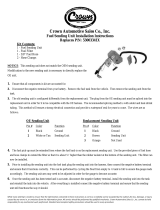
Fig 2
In From
Tank
Out To
Engine
Fuel Pump Flow Direction
(+)
(-)
Fig 3

Part Number 3604
Brochure #63-3604
©2013 Edelbrock LLC
Rev. 3/27/13 - QT/mc
2
INSTALLATION TIPS AND PROCEDURES
Make sure to perform the installation in a well ventilated area
away from any potential fire hazards. Gasoline fumes are toxic
and highly flammable.
1. Disconnect the NEGATIVE (-) terminal on the battery.
2. Release the pressure in the fuel system by removing the gas
cap.
3. Remove the fuel lines from the factory mechanical fuel pump
and unbolt the fuel pump from the engine. Thoroughly clean
the block’s mating surface and install a fuel pump block-off
plate (required - not included) specific for your application.
Make sure to use the appropriate fuel pump block-off plate
gasket and bolts.
NOTE: If using a low pressure electric fuel pump, a fuel
pump block-off plate may already be present. All other
components of the electric fuel pump must be removed.
4. Disconnect the factory hard line from the fuel tank sending
unit.
NOTE: The factory hard lines can be completely removed
if not used as a return line (see Step 5). If not removing or
using as a return line, it is recommended to cap the ends of
the factory hard line to prevent contamination.
5. To ensure proper fuel pressure and delivery, a bypass fuel
return line inlet must be installed onto the fuel tank sending
unit at this time. There are three options for installing a
bypass return line:
NOTE: If a fuel return line is not present, modifications to the
fuel tank are required to route the fuel return line through
the sending unit plate back into the tank. The first two
methods listed below require welding and should be done
by a Professional.
Please refer to Page 3 for more details on the three bypass
fuel return line methods.
1. Rubber Return Line (Supplied 5/16” Rubber Line) or SAE
J30R7 (50 PSI) working pressure:
a. Method 1a - Weld in a 5/16” hard line inlet onto the
sending unit cover plate.
b. Method 1b - Install a -6 AN Bulkhead fitting onto the
sending unit cover plate (does not require welding).
2. Use the vehicle’s existing fuel hard line as the fuel return
line with modification to the sending unit and pick-up.
3. Use the vehicle’s existing return line (if equipped) as the
fuel return line.
NOTE: Whichever method you use to install the fuel return
line, it is very important to locate the in-tank fuel return
line, as far away as possible, from the fuel pick-up (fuel
feed line). This will eliminate any aerated return fuel that
can be drawn into the fuel pickup.
6. Determine the ideal mounting location for the new high
pressure electronic fuel pump and primary fuel filter using
the supplied mounting hardware. The primary fuel filter
and the fuel pump must be mounted at or below the lowest
point of the fuel tank. The fuel pump must also be mounted
within 3 feet of the fuel tank as it is designed to push fuel
from the rear of the vehicle, towards the engine bay. Fuel
pump failure will occur if not mounted within the required
specification.
Fuel Tank
Fuel Filter
Fuel Pump
The Fuel Filter and Pump must be
mounted at or below the lowest
point of the fuel tank and within 3’
of the tank outlet
3’ Max
NOTE: Additional mounting brackets, not included in this
kit, may be required to securely mount the fuel pump and
fuel filters. Please note that the fuel pump is directional
and must be installed with the terminal connections flowing
towards the engine (See Figure 2 on Page 1).
7. Using the 3/8” high pressure fuel line, connect the fuel outlet
on the fuel tank sending unit to the primary fuel filter. Cut the
fuel line to length as needed and secure with hose clamps.
NOTE: The supplied 3/8” high pressure rubber fuel line must
be used as the main fuel supply line.
8. Connect the primary fuel filter to the fuel pump using the
3/8” fuel line. Cut fuel line to length as needed and secure
with hose clamps.
9. Determine the ideal mounting location for the secondary fuel
filter. This can be anywhere between the fuel pump and the
fuel pressure regulator. Securely mount secondary fuel filter
using the supplied mounting clamp.
NOTE: The primary and secondary fuel filters must be used
in conjunction to avoid contaminating the fuel pump and the
EFI system. Any failures associated with contaminants will
void the warranty of the fuel pump and the EFI system (if
applicable).
10. Connect the 3/8” fuel line to the fuel pump and secure with
a hose clamp. Route the fuel line towards the secondary
fuel filter. Cut fuel line to length as needed and secure with
a hose clamp.
NOTE: DO NOT route fuel line around sharp objects, moving
components or exhaust components.
11. Connect the 3/8” fuel line to the secondary filter and route it
towards the engine bay.
12. Use the appropriate fitting that will attach to the fuel return
line inlet installed on Step 5. Connect your return line to the
sending unit inlet.

Part Number 3604
Brochure #63-3604
©2013 Edelbrock LLC
Rev. 3/27/13 - QT/mc
3
13. Connect the POSITIVE (+) and NEGATIVE (-) leads on the fuel
pump harness, supplied in the EFI kit (if applicable), to the
fuel pump accordingly (See Figure 3).
14. Route the fuel pump harness and fuel return line towards the
front of the vehicle into the engine bay.
NOTE: DO NOT route around sharp objects, moving
components or exhaust components. Make sure the fuel
lines and fuel pump harness do not hang below the chassis.
15. Secure the fuel lines and fuel pump harness using the
provided tie wraps, every 8-10 inches. Additional tie wraps
may be required.
16. Assemble the fuel pressure regulator using the provided
fittings and O-rings (See Figure 4). Loosely mount the
regulator in an accessible location using the supplied
mounting bracket.
NOTE: Do not attempt to adjust the fuel pressure without
the use of a fuel pressure gauge (not included). If using
the Edelbrock E-Street EFI system, the fuel pressure can be
monitored on the Display Screens using the tablet.
Fig 4
Fuel In/Out
Fuel In/Out
Return to Tank
Vacuum
Fitting
Adjustment
Screw
17. Using the supplied Twist-Lok fittings (See Figure 4), connect
the 3/8” fuel line from the secondary fuel filter to the fuel
pressure regulator inlet. Trim fuel line to length as needed.
NOTE: Twist-Lok fittings do not require additional hose
clamps.
Depending on your application and specific routing needs,
additional fuel fittings may be required. These fittings are
available at your local Russell Performance dealer. The
regulator uses -6 AN fittings.
18. Using the supplied Twist-Lok fittings and the 3/8” fuel line,
connect the fuel pressure regulator to the fuel rail of the EFI
system (See Figure 4). Trim fuel line to length as needed.
19. Using the supplied fittings (if using supplied 5/16” rubber fuel
line), connect the fuel return line to the bottom fitting on the
fuel pressure regulator (See Figure 4).
20. If using this fuel system on the Edelbrock E-Street (#3600),
the vacuum fitting on the fuel pressure regulator must
reference atmospheric pressure (leave unplugged).
NOTE: If using this kit on other EFI systems, please refer
to the EFI’s Owner’s Manual for additional information on
Vacuum Pressure reference.
21. If using the Edelbrock E-Street EFI system, the supplied relay
harness will connect to the Fuel Pump connector on the
E-Street main harness and the female end will connect to
the fuel pump harness. The power lead on the relay harness
must be connected to a Constant +12V source.
Relay
Fuse
+12V Connection
at Battery
Dark Grey Female
To Fuel Pump Harness
Light Grey Male To
Fuel Pump Connector on
E-Street Main Harness
NOTE: The connector ends can be cut off if using the relay
harness on other EFI systems. Please refer to the EFI System’s
wiring diagram for more information.
22. Reconnect the NEGATIVE (-) terminal on the battery and turn
the key to the “ON” position, DO NOT start the vehicle yet.
With the key in the “ON” position, check all fuel connections
for leaks. If leaks are present, immediately turn the key off
and repair all leaks before continuing.
23. If leaks are not present, turn the key off and back to the “ON”
position to verify the pump is priming.
NOTE: The following fuel pump priming procedure is intended
for the Edelbrock E-Street EFI system only. If using another
EFI system, please refer to the installation manual of that
system for specific fuel pump priming procedures.
Pump will make a pumping/priming noise for 5-8 seconds
when the key is first turned on. Fuel pressure can also be
verified with a fuel pressure gauge (if equipped). If using
the Edelbrock E-Street EFI system, the fuel pressure can be
monitored on the Display Screens using the tablet. If pump
is not priming, verify that the fuel pump harness and relay
harness are installed correctly.
24. If the fuel pump is cycling, the fuel system can now be primed.
This is done by cycling the key on and off 3-4 times to build a
steady pressure in the fuel system. Once the fuel system has
been primed, the installation of the fuel system is complete.
NOTE: It is not advised to start the vehicle until the completion
of the EFI installation. Once the vehicle can be started, double
check all fuel connections for leaks.

Part Number 3604
Brochure #63-3604
©2013 Edelbrock LLC
Rev. 3/27/13 - QT/mc
4
RUBBER RETURN LINE
Method 1a - Weld in a 5/16” Hard Line Fitting
WARNING: It is never recommended to perform any type of
welding on your existing fuel sending unit as fuel and fuel vapors
may be present. To avoid fire hazards, it’s highly recommended
to perform this method on a brand new sending unit.
Remove the sending unit from the fuel tank and discard. Drill a
5/16” hole in the sending unit plate adjacent to where the main
line enters the tank. This will be the hole for your return line.
Insert a straight 5/16” hard line (available at most radiator
shops) into the hole so that the line extends 1-2 inches on both
sides of the sending unit plate. Secure the hard line and weld it
to the sending unit cover plate. Attach at least 18-24 inches of
5/16” submersible fuel hose (Gates #27093 SA30R10 or
equivalent) to the hard line that will extend into the fuel tank,
secure with a hose clamp. Direct the in-tank fuel line away
from the pick-up and secure it to the fuel pickup line using tie
wraps. Install the sending unit cover plate onto the fuel tank.
5/16”
HARD LINE
GAS TANK
COVER PLATE
WIRE TIE
HOSE CLAMP
5/16” RUBBER
HOSE (18-24” LONG)
DIRECT RETURN FUEL
AWAY FROM PICK-UP
ORIGINAL FUEL
PICK-UP TUBE
RUBBER HOSE METHOD
Method 1b - Using a -6 AN Bulkhead Fitting
Remove the sending unit from the fuel tank. Drill a 9/16” hole
in the sending unit plate adjacent to where the main line enters
the tank. This will be the hole for your return line. Insert a
-6 AN bulkhead fitting (available at your Russell Performance
dealer - #670850) into the hole with the tapered end of the
fitting on the inside of the plate. Fasten the fitting to the plate
with the nut and PTFE washer. Install approximately 18-24
inches of 5/16” submersible fuel hose (Gates #27093 SA30R10
or equivalent) to a -6 AN hose end fitting (not included) and
connect the hose end fitting to the tapered end (inside fuel tank)
of the bulkhead fitting. Direct the line away from the pick-up
and secure it to the fuel pickup line using tie wraps. Reinstall
the sending unit cover plate. Another -6 AN hose end fitting
will be required for the 5/16” return line that will connect to the
other end of the bulkhead fitting.
NOTE: This method does not require welding.
#6 AN
BULKHEAD
GAS TANK
COVER PLATE
WIRE TIE
5/16” RUBBER
HOSE (18-24” LONG)
DIRECT RETURN FUEL
AWAY FROM PICK-UP
ORIGINAL FUEL
PICK-UP TUBE
#6 AN
HOSE END
FITTING
BULKHEAD FITTING METHOD
Edelbrock LLC • 2700 California St. • Torrance, CA 90503
Tech-Line: 800-416-8628
®
HARD RETURN LINE METHOD
Use the factory hard fuel supply line as a return line.
WARNING: It is never recommended to perform any type of
welding on your existing fuel sending unit as fuel and fuel vapors
may be present. To avoid fire hazards, it’s highly recommended
to perform this method on a brand new sending unit.
Remove the sending unit from the fuel tank and discard. Drill a
5/16” hole in the sending unit plate adjacent to where the main
line enters the tank. This will be the hole for your return line.
Insert the 5/16” hard line (available at most radiator shops) into
the hole. The hard line should extend through the hole 1 to 2
inches on the outside of the plate. On the inside of the plate,
the hard line should follow the contours of the fuel pickup line
with the end of the return line bent 12-18 inches away from the
pick-up sock. Weld the 5/16” hard line into place and secure to
the fuel pickup line with a support brace. Reinstall sending unit
cover plate and connect 5/16” hard line inlet to the factory fuel
supply line.
NEW 5/16” HARD LINE
GAS TANK
COVER PLATE
ORIGINAL FUEL
PICK-UP TUBE
DIRECT RETURN FUEL
AWAY FROM PICK-UP
SUPPORT
BRACKET
HARD RETURN LINE METHOD
FACTORY RETURN LINE METHOD
If vehicle is equipped with a factory fuel return line. Simply connect
the return line located in the engine bay to the return outlet on
the fuel pressure regulator. Modifications may be required to the
factory return line. Please use appropriate fuel fittings to avoid
any fuel leaks that may occur.
NOTE: Whichever method you use to install the fuel return line,
it is very important to locate the in-tank fuel return line, as far
away as possible, from the fuel pick-up (fuel feed line). This will
eliminate any aerated return fuel that can be drawn into the fuel
pickup.
/