ESAB A21 PRH 40-115 User manual
- Category
- Welding System
- Type
- User manual
This manual is also suitable for

PRH 6--40 , 25--90 valid for serial NO 721 XXX--XXXX
PRH 40--115 valid for serial NO 734 XXX--XXXX
0457 599 041 990615
A21 PRH 6- 40
A21 PRH 25- 90
A21 PRH 40- 115
105107106023104022041
Instruction manual
Betriebsanweisung
Manuel d’instructions
Gebruiksaanwijzing

-- 2 --
Rights reserved to alter specifications without notice.
Änderungen vorbehalten.
Sous réserve de modifications sans avis préalable.
Recht op wijzigingen zonder voorafgaande mededeling voorbehouden.
ENGLISH 3..............................................
DEUTSCH 14.............................................
FRANÇAIS 25.............................................
NEDERLANDS 37.........................................

ENGLISH
-- 3 --
TOCe
1 DIRECTIVE 4........................................................
2SAFETY 4...........................................................
3 INTRODUCTION 5...................................................
3.1 General 5..................................................................
3.2 Technical data 6............................................................
4 INSTALLATION 6....................................................
4.1 General 6..................................................................
4.2 Connections 6..............................................................
5 OPERATION 7.......................................................
5.1 General 7..................................................................
5.2 How to open the intermediate part of the tube welding tool 7......................
5.3 Fixation of the welding tool for welding 8.......................................
5.4 Adjusting the tungsten electrode 8.............................................
5.5 Welding start 9..............................................................
5.6 Welding in confined spaces 10.................................................
6 MAINTENANCE 10....................................................
6.1 General 10..................................................................
6.2 Every day 10................................................................
6.3 Every month 11..............................................................
6.4 As necessary 11.............................................................
6.5 Replacing the tungsten electrode 11............................................
6.6 Replacing the clamping jaw collet 11............................................
7 ACCESSORIES 12....................................................
8 ORDERING OF SPARE PARTS 13......................................
DIMENSION DRAWING 48................................................
DIAGRAM 49............................................................
SPARE PARTS LIST 51...................................................

-- 4 --
dsb1d1ea
1 DIRECTIVE
DECLARATION OF CONFORMITY
Esab Welding Equipment AB, 695 81 Laxå, Sweden, declares that tube welding tool
A21 PRH 6--40 / 25--90 / 40--115 from serial number 721 onwards, conforms to stan -
dard EN 60292, in accordance with the requirements of directive (89/392/EEC) and
appendix (93/68/EEC) and standard EN 50199 in accordance with the requirements
of directive (89/336/EEC) and appendix (93/68/EEC).
-- -- -- -- -- -- -- -- -- -- -- -- -- -- -- -- -- -- -- -- -- -- -- -- -- -- -- -- -- -- -- -- -- -- -- -- -- -- -- -- -- -- -- -- -- -- -- -- -- -- -- -- -- -- -- -- -- -- -- -- -- -- -- --------
Paul Karlsson
Managing Director
Esab Welding Equipment AB
695 81 LAXÅ
SWEDEN Tel: + 46 584 81000 Fax: + 46 584 12336
Laxå 1999.01.07
2SAFETY
Users of ESAB welding equipment have the ultimate responsibility for ensuring that anyone who
works on or near the equipment observes all the relevant safety precautions.
Safety precautions must meet the requirements that apply to this type of welding equipment.
The following recommendations should be observed in addition to the standard regulations that apply
to the work place.
All work must be carried out by trained personnel well familiar with the operation of the welding equip-
ment.
Incorrect operation of the equipment may lead to hazardous situations which can result in injury to the
operator and damage to the equipment.
1. Anyone who uses the welding equipment must be familiar with:
S its operation
S its function
S relevant safety precautions
S welding
2. The operator must ensure that:
S no unauthorized person is stationed within the working area of the equipment when it is
started up.
S that no--one is unprotected when the arc is struck
3. The work place must:
S be suitable for the purpose
S be free from draughts
4. Personal safety equipment
S Always wear recommended personal safety equipment, such as safety glasses, flame--proof
clothing, safety gloves.
S Do not wear loose--fitting items, such as scarves, bracelets, rings, etc., which could become
trapped or cause burns.
5. General precautions
S Make sure the return cable is connected securely.
S Work on high voltage equipment shall only be carried out by a qualified electrician.
S Appropriate fire extinquishing equipment must be clearly marked and close at hand.
S Lubrication and maintenance must not be carried out on the equipment during operation.
GB

-- 5 --
dsb1d1ea
WARNING
READ AND UNDERSTAND THE INSTRUCTION MANUAL BEFORE INSTALLING OR OPERATING.
ARC WELDING AND CUTTING CAN BE INJURIOUS TO YOURSELF AND OTHERS. TAKE PRECAU-
TIONS WHEN WELDING. ASK FOR YOUR EMPLOYER’S SAFETY PRACTICES WHICH SHOULD BE
BASED ON MANUFACTURERS’ HAZARD DATA.
ELECTRIC SHOCK -- Can kill
S Install and earth the welding unit in accordance with applicable standards.
S Do not touch live electrical parts or electrodes with bare skin, wet gloves or wet clothing.
S Insulate yourself from earth and the workpiece.
S Ensure your working stance is safe.
FUMES AND GASES -- Can be d angerous to health
S Keep your head out of the fumes.
S Use ventilation, extraction at the arc, or both, to keep fumes and gases from your breathing zone and
the general area.
ARC RAYS -- Can injure eyes and burn skin.
S Protect your eyes and body. Use the correct welding screen and filter lens and wear protective
clothing.
S Protect bystanders with suitable screens or curtains.
FIRE HAZARD
S Sparks (spatter) can cause fire. Make sure therefore that there are no inflammable materials nearby.
NOISE -- Excessive noise can damage hearing
S Protect your ears. Use ear defenders or other hearing protection.
S Warn bystanders of the risk.
MALFUNCTION -- Call for expert assistance in the event of malfunction.
PROTECT YOURSELF AND OTHERS!
3 INTRODUCTION
3.1 General
A21 PRH 6--40 / 25--90 / 40--115 is a series of enclosed water--cooled tools,
designed for TIG welding of tube joints.
Enclosed here means that the tube joint during the welding is surrounded by a
closed chamber in which a gas shield of inert gas protects the tungsten electrode,
the weld joint and the tube from oxidation.
During welding only the gear collar and the electrode holder rotate round the tube.
The tube welding tool is clamped and centred on the tube by way of a clamping
device.
To make it possible to take up the tolerances within the nominal tube dimension the
clamping device is spring--mounted.
The collets of the clamping jaws are exchangeable so as to fit different tube
dimensions (see page 11).
The tube welding tools are designed for connection to the power sources LTO 160,
LTO 250, LT P 450 and LTS 320.
GB

-- 6 --
dsb1d1ea
3.2 Technical data
A21 PRH 6 -- 40 A21 PRH 25 -- 90 A21 PRH 40 -- 115
Max. continuous welding
current at 100% duty cycle
100 A 100 A 100 A
Max. pulsed welding current 150 A 150 A 150 A
Working range (external tu-
be diameter)
6-- 40 mm 25--90 mm 40--115 mm
Rotation speed 0.14 -- 2.8 r/min 0.08--1.62 r/min 0.10--1.36 r/min
Weight including cable and
hose bundle
7.5 kg 10 kg 12 kg
Length of hose bundle 5m 5m 5m
Diameter, tungsten electrode 1.6 mm and 2.4 mm 1.6 mm and 2.4 mm 1.6 mm and 2.4 mm
Drive unit
Armature voltage
Max. armature current
Gear ratio
48 V DC
0.30--0.55 A DC
246:1
48 V DC
0.30--0.55 A DC
246:1
48 V DC
0.30--0.55 A DC
134:1
4 INSTALLATION
4.1 General
The installation sh all be executed b y a professional.
WARNING!
Rotating parts can cause injury, take great care.
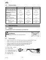
4.2 Connections
S Power source LTO 160 / LTO 250, see instruction m anual 0456 779 xxx.
S Power source LTP 450, see instruction manual 0456 634 xxx.
S Power source LTS 320, see instruction manual 0457 690 xxx.
S Cooling unit OCF2, see instruction m anual 0457 680 xxx.
Make sure the cooling capacity is sufficient.
A Motor cable -- rotation
B Return cable
C Cooling water hose, in
D Cooling water hose, out
E W elding cable
F Gas hose, out
GB

-- 7 --
dsb1d1ea
5OPERATION
5.1 General
During the welding the tool can be very hot, so take great care!
WARNING!
General safety regulations for the handling of the equipment appear from
page 4. Read through before you start using the equipment!
To avoid the welding tool being damaged, check that the return cable is
connected to the workpiece and that the tungsten electrode is in start position
before the welding is started.
WARNING!
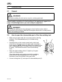
5.2 How to open the intermediate part of the tube welding tool
S Make sure the gear collar (9) is in home position (starting
position). (The intermediate part (6) is locked during
welding.)
S Use the button on the remote control unit or the hand
wheel (8) on the tool to move the gear collar manually to
home position. NOTE. When the wheel (8) is pushed in, the
gear is disengaged (pull it out again when the positioning
is ready). This should be done to avoid unnecessary
wear.
S When the light--emitting diode (7) lights up, the gear
collar is in home position.
If the tube welding tool is not connected to a welding
power source, the clamping jaw (4) or (5) must be
opened to check the position of the gear collar.
S Loosen locking lever (2) and open the intermediate part ( 6).
GB

-- 8 --
dsb1d1ea
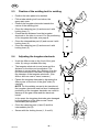
5.3 Fixation of the welding tool for welding
S Position the tube parts to be welded.
S Fit the tube welding tool from below, the
upper part open.
S Position the tungsten electrode towards the
centre of the welding joint.
S Close the clamping jaw (4) and secure it with
locking lever (1).
S Check that the distance from the tungsten
electrode to the tube is correct. F or the positioning
of the tungsten electrode, see page 8.
S Close the intermediate part ( 6) and secure it with
locking lever (2).
S Close the clamping jaw (5) and secure it with
locking lever (3).
5.4 Adjusting the tungsten electrode
S Undo the Allen screw on the front of the gear
collar ( 9) using a suitable Allen key.
S The tungsten electrode is now loose and the
distance to the tube can be adjusted. The
distance is correct when the distance from the
tip of the electrode to the tube corresponds to
the diameter of the tungsten electrode. (Can
differ a bit from case to case, however.)
S Fasten the tungsten electrode by tightening the
Allen screw on the front of the gear collar (9)
carefully.
NOTE. For the welding current to be transferred,
the tungsten electrode must be fixed. Inadequate
positioning of the tungsten electrode can result in
damage to the gear collar and the electrode
holder.
In the event the tungsten electrode gets damaged
by the tightening of the Allen screw it must
immediately be replaced.
S Close the clamping jaws (4 and 5) and the
intermediate part (6).
S Secure with the locking levers (1, 2 and 3).
GB

-- 9 --
dsb1d1ea
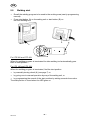
5.5 Welding start
S Recall the welding program to be used to the working area (see tje programming
manual).
S Press start button (A) on the setting unit or start button (B) on
the tube welding tool.
For LTS 320 and LTP 450:
When the welding program is terminated the tube welding tool automatically goes
back to start position.
For LTO 160 and LTO 250:
When the welding program is terminated, find the start position
S by manually turning wheel (8) (see page 7) or
S by going over to manual operation by way of the setting unit, or
S by programming the search of the start position by setting a search time value.
The start position is found when the LED goes on.
GB

-- 1 0 --
dsb1d1ea
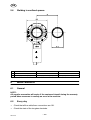
5.6 Welding in confined spaces
A21 PRH 6--40 A21 PRH 25--90 A21 PRH 40--115
D 123 mm 197 mm 220 mm
C (d/2) + 10 + (D/2) (d/2) + 10 + (D/2) (d/2) + 10 + (D/2)
6 MAINTENANCE
6.1 General
NOTE:
All supplier warran t ies will expire if the customer h imself during th e warranty
period takes measures t o remedy an error in the machine.
6.2 Every day
S Check that all the cable/hose connections are OK.
S Check the state of the tungsten electrode.
GB

-- 1 1 --
dsb1d1ea
6.3 Every month
S Check that all built--in components are properly positioned.
S Check that the clamping jaws have no m echanical damages. If so, replace the
damaged part.
6.4 As necessary
Grease the gear collar using Nies P34.
After 500 welds per to o l
S Dismount the electrode holder and remove the oxide layer inside and outside.
6.5 Replacing the tungsten electrode
When replacing the tungsten electrode, cut the electrode into the desired length and
grind it for the desired angle.
6.6 Replacing the clamping jaw collet
S Make sure the gear collar (9) is in home position
(see page 7).
S Open locking lever (1), this unlocks the upper
part of the locking lever (1b).
S Open the clamping jaw (4).
S Dismount the existing clamping jaw collet (7)
undoing the Allen screw.
S Fit the desired collet and tighten the Allen screw.
S Replace the other clamping jaw collets in the same
way.
Important!
The upper clamping jaw collets should not be tightened too
hard. Some spring movement must remain (about 2 mm).
The welding current is earthed over the lower clamping jaws (8), so make sure the
Allen screws of the lower clamping jaw collets in particular are properly tightened.
Custom--made clamping jaw collets can be ordered from your ESAB retailer.
By way of a turning fixture and blanks available as accessories, you can produce
your own clamping jaw collets, (see Accessories on page 12).
GB

-- 1 2 --
dsb1d1ea
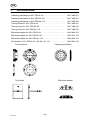
7 ACCESSORIES
ClampingjawblanksforA21PRH6--40 ........................ 0457 485 001
ClampingjawblanksforA21PRH25--90....................... 0457 485 002
ClampingjawblanksforA21PRH40--115...................... 0457 485 003
TurningfixtureforA21PRH6--40 ............................. 0457 486 001
TurningfixtureforA21PRH25--90 ............................ 0457 486 002
TurningfixtureforA21PRH40--115 ........................... 0457 486 003
Electrode adapter for A21 PRH 6--40 .......................... 0456 940 123
Electrode adapter for A21 PRH 25--90 ......................... 0456 941 123
Electrode adapter for A21 PRH 40--115 ........................ 0456 942 123
ToolholderforA21PRH6--40/25--90/40--115 ................. 0456 940 122
Clamping jaw blanksTurning fixture
Tool holder Electrode adapter
GB

-- 1 3 --
dsb1d1ea
8 ORDERING OF SPARE PARTS
A21 PRH 6--40 / 25--90 / 40--115 is designed and tested in accordance with
the EN 60292 (IEC 292) international standard.
It is the obligation of the service unit which has carried out the service or re-
pair work to make sure that the product still conforms to the said standard.
Spare parts are ordered through your nearest ESAB representative, see back cover.
When ordering spare parts, please state machine type and number as well as desig-
nation and spare part number as shown in the spare parts list on page 51.
This will simplify dispatch and ensure you get the right part.
GB
-
 1
1
-
 2
2
-
 3
3
-
 4
4
-
 5
5
-
 6
6
-
 7
7
-
 8
8
-
 9
9
-
 10
10
-
 11
11
-
 12
12
-
 13
13


ESAB A21 PRH 40-115 User manual
- Category
- Welding System
- Type
- User manual
- This manual is also suitable for
Ask a question and I''ll find the answer in the document
Finding information in a document is now easier with AI
Related papers
-
ESAB PRH 3-38 User manual
-
-
-
-
ESAB PRE A21 PRE User manual
-
-
-
-
-
