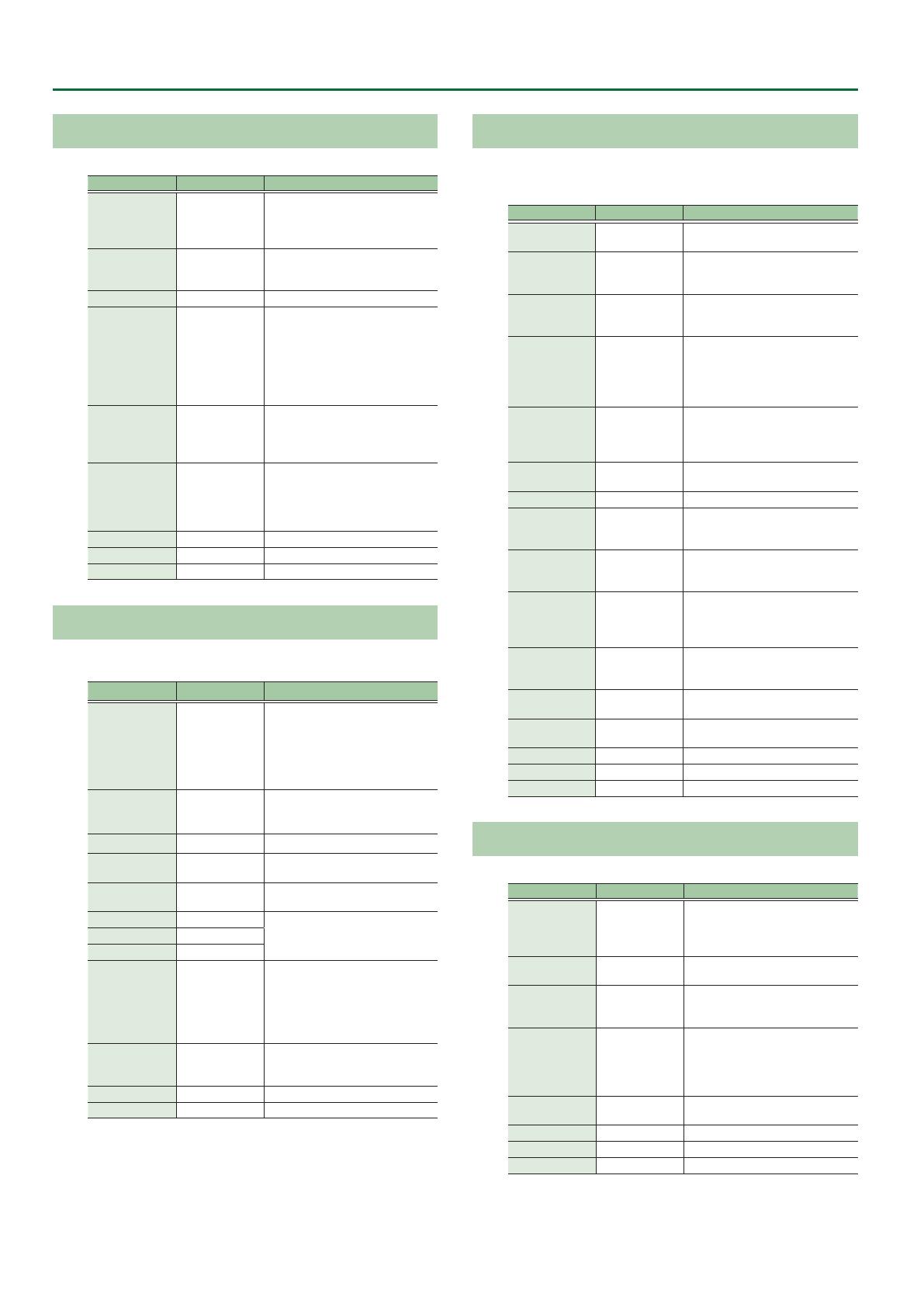
Roland TD-17 Datasheet

Category
Audio mixers
Type
Datasheet
Data List
* The illustration shows the TD-17.
© 2018 Roland Corporation
2
Contents
DRUM KIT . . . . . . . . . . . . . . . . . . . . . . . . . . . . . . . . . . . . . . . . . . . . . . . . . 3
KIT Screen . . . . . . . . . . . . . . . . . . . . . . . . . . . . . . . . . . . . . . . . . . . . . . 3
CLICK . . . . . . . . . . . . . . . . . . . . . . . . . . . . . . . . . . . . . . . . . . . . . . . . . . . . . 3
COACH . . . . . . . . . . . . . . . . . . . . . . . . . . . . . . . . . . . . . . . . . . . . . . . . . . . . 4
TIME CHECK . . . . . . . . . . . . . . . . . . . . . . . . . . . . . . . . . . . . . . . 4
QUIET COUNT . . . . . . . . . . . . . . . . . . . . . . . . . . . . . . . . . . . . . 4
WARM UPS . . . . . . . . . . . . . . . . . . . . . . . . . . . . . . . . . . . . . . . . 4
SONG . . . . . . . . . . . . . . . . . . . . . . . . . . . . . . . . . . . . . . . . . . . . . . . . . . . . . 5
INSTRUMENT . . . . . . . . . . . . . . . . . . . . . . . . . . . . . . . . . . . . . . . . . . . . . 6
ASSIGN . . . . . . . . . . . . . . . . . . . . . . . . . . . . . . . . . . . . . . . . . . . . . . . . . 6
LEVEL . . . . . . . . . . . . . . . . . . . . . . . . . . . . . . . . . . . . . . . . . . . . . . . . . . 7
TUNING . . . . . . . . . . . . . . . . . . . . . . . . . . . . . . . . . . . . . . . . . . . . . . . . 7
MUFFLING . . . . . . . . . . . . . . . . . . . . . . . . . . . . . . . . . . . . . . . . . . . . . . 7
USER SAMPLE . . . . . . . . . . . . . . . . . . . . . . . . . . . . . . . . . . . . . . . . . . . 8
OTHER . . . . . . . . . . . . . . . . . . . . . . . . . . . . . . . . . . . . . . . . . . . . . . . . . 9
AMBIENCE . . . . . . . . . . . . . . . . . . . . . . . . . . . . . . . . . . . . . . . . 9
MULTI FX . . . . . . . . . . . . . . . . . . . . . . . . . . . . . . . . . . . . . . . . . . 10
PAD EQ . . . . . . . . . . . . . . . . . . . . . . . . . . . . . . . . . . . . . . . . . . . 10
VOLUME . . . . . . . . . . . . . . . . . . . . . . . . . . . . . . . . . . . . . . . . . . 10
MIDI NOTE . . . . . . . . . . . . . . . . . . . . . . . . . . . . . . . . . . . . . . . . 11
SETUP . . . . . . . . . . . . . . . . . . . . . . . . . . . . . . . . . . . . . . . . . . . . . . . . . . . . 12
Bass/Treble . . . . . . . . . . . . . . . . . . . . . . . . . . . . . . . . . . . . . . . . 12
Pad Settings . . . . . . . . . . . . . . . . . . . . . . . . . . . . . . . . . . . . . . . 12
Hi-Hat Settings . . . . . . . . . . . . . . . . . . . . . . . . . . . . . . . . . . . . 14
MIDI . . . . . . . . . . . . . . . . . . . . . . . . . . . . . . . . . . . . . . . . . . . . . . 15
LCD . . . . . . . . . . . . . . . . . . . . . . . . . . . . . . . . . . . . . . . . . . . . . . 16
USB . . . . . . . . . . . . . . . . . . . . . . . . . . . . . . . . . . . . . . . . . . . . . . 16
AUTO OFF . . . . . . . . . . . . . . . . . . . . . . . . . . . . . . . . . . . . . . . . . 16
System Info. . . . . . . . . . . . . . . . . . . . . . . . . . . . . . . . . . . . . . . . 16
Multi-Eect Parameters . . . . . . . . . . . . . . . . . . . . . . . . . . . . . . . . . . . 17
DELAY . . . . . . . . . . . . . . . . . . . . . . . . . . . . . . . . . . . . . . . . . . . . 18
TAPE ECHO . . . . . . . . . . . . . . . . . . . . . . . . . . . . . . . . . . . . . . . . 18
REVERSE DELAY . . . . . . . . . . . . . . . . . . . . . . . . . . . . . . . . . . . . 18
3TAP PAN DELAY . . . . . . . . . . . . . . . . . . . . . . . . . . . . . . . . . . . 18
OD
0
DELAY . . . . . . . . . . . . . . . . . . . . . . . . . . . . . . . . . . . . . . 19
DS
0
DELAY . . . . . . . . . . . . . . . . . . . . . . . . . . . . . . . . . . . . . . . 19
CHORUS . . . . . . . . . . . . . . . . . . . . . . . . . . . . . . . . . . . . . . . . . . 19
SPACE-D . . . . . . . . . . . . . . . . . . . . . . . . . . . . . . . . . . . . . . . . . . 19
OD
0
CHORUS . . . . . . . . . . . . . . . . . . . . . . . . . . . . . . . . . . . . 19
DS
0
CHORUS . . . . . . . . . . . . . . . . . . . . . . . . . . . . . . . . . . . . . 19
PHASER A . . . . . . . . . . . . . . . . . . . . . . . . . . . . . . . . . . . . . . . . . 20
PHASER B . . . . . . . . . . . . . . . . . . . . . . . . . . . . . . . . . . . . . . . . . 20
STEP PHASER . . . . . . . . . . . . . . . . . . . . . . . . . . . . . . . . . . . . . . 20
FLANGER . . . . . . . . . . . . . . . . . . . . . . . . . . . . . . . . . . . . . . . . . . 20
REVERB . . . . . . . . . . . . . . . . . . . . . . . . . . . . . . . . . . . . . . . . . . . 21
LONG REVERB . . . . . . . . . . . . . . . . . . . . . . . . . . . . . . . . . . . . . 21
SUPER FILTER . . . . . . . . . . . . . . . . . . . . . . . . . . . . . . . . . . . . . . 21
FILTER+DRIVE . . . . . . . . . . . . . . . . . . . . . . . . . . . . . . . . . . . . . . 21
AUTO WAH . . . . . . . . . . . . . . . . . . . . . . . . . . . . . . . . . . . . . . . . 22
OD/DS
0
TWAH . . . . . . . . . . . . . . . . . . . . . . . . . . . . . . . . . . . 22
LOFI COMPRESS . . . . . . . . . . . . . . . . . . . . . . . . . . . . . . . . . . . . 22
DISTORTION . . . . . . . . . . . . . . . . . . . . . . . . . . . . . . . . . . . . . . . 22
OVERDRIVE . . . . . . . . . . . . . . . . . . . . . . . . . . . . . . . . . . . . . . . . 22
SATURATOR . . . . . . . . . . . . . . . . . . . . . . . . . . . . . . . . . . . . . . . 22
T-SCREAM . . . . . . . . . . . . . . . . . . . . . . . . . . . . . . . . . . . . . . . . . 23
BIT CRUSHER . . . . . . . . . . . . . . . . . . . . . . . . . . . . . . . . . . . . . . 23
ISOLATOR . . . . . . . . . . . . . . . . . . . . . . . . . . . . . . . . . . . . . . . . . 23
RING MODULATOR . . . . . . . . . . . . . . . . . . . . . . . . . . . . . . . . . 23
PITCH SHIFTER . . . . . . . . . . . . . . . . . . . . . . . . . . . . . . . . . . . . . 23
AUTO PAN . . . . . . . . . . . . . . . . . . . . . . . . . . . . . . . . . . . . . . . . . 23
Kit List . . . . . . . . . . . . . . . . . . . . . . . . . . . . . . . . . . . . . . . . . . . . . . . . . . . . 24
Instrument List . . . . . . . . . . . . . . . . . . . . . . . . . . . . . . . . . . . . . . . . . . . 25
User Sample List . . . . . . . . . . . . . . . . . . . . . . . . . . . . . . . . . . . . . . . . . . 30
Song List . . . . . . . . . . . . . . . . . . . . . . . . . . . . . . . . . . . . . . . . . . . . . . . . . . 30
Kit Structure . . . . . . . . . . . . . . . . . . . . . . . . . . . . . . . . . . . . . . . . . . . . . . 31
3
DRUM KIT
KIT Screen
1. Press the [DRUM KIT] button.
The KIT screen appears.
Parameter Value Explanation
XSTICK OFF, ON Species whether a snare pad produces the cross-stick sound (ON) or not (OFF).
MIX VOL ([2] button)
Audio In -INF–+6.0 dB Input volume of the device connected to the MIX IN jack and Bluetooth (*1)
Click -INF–+6.0 dB Volume of the click
Song -INF–+6.0 dB Volume of the song
Guide Track -INF–+6.0 dB Volume of the guide track
*1 TD-17-L excepted
CLICK
1. Press the [CLICK] button.
The CLICK screen appears.
Parameter Value Explanation
Tempo*1 20–260 Tempo
[F3] button OFF, ON Turns click on/o.
MENU ([F1] button)
Beat*1 1–9 Number of beats per measure
Rhythm Type
Interval of the click
Sound
METRONOME, CLICK, VOICE, BEEP 1,
BEEP 2, TEK CLICK, STICKS, CLAVES,
WOOD BLOCK, COWBELL, AGOGO,
TRIANGLE, TAMBOURINE, MARACAS,
CABASA
Sound for the click
Pan L30–CENTER–R30 Stereo position of the click
MIX VOL ([2] button)
This is the same parameter as the KIT screens MIX VOL ([F2] button).
4
1. Press the [COACH] button.
The COACH MENU screen appears.
2. Press a function button to select a practice menu.
3. Press the [F2] (MENU) button.
The coach menu settings screen appears.
TIME CHECK
Parameter Value Explanation
SETUP tab
Score
Species whether the score will be shown in the screen.
OFF
Your performance will not be scored.
Only the timing will be checked.
ON (4, 8, 16, 32 meas)
The score will be shown in the screen.
You can also specify the number of measures you’ll practice before being scored.
Grade
Species the strictness of scoring.
EASY Normal
HARD Timing will be checked more strictly.
Display 1
Display 2
In the screen, select the pad for which a timing graph will be shown.
Gauge
LEFT BEHIND The left side of the timing graph is shown as BEHIND (late).
LEFT AHEAD The left side of the timing graph is shown as AHEAD (early).
CLICK tab
This parameter is in common with the MENU ([1] button) of the CLICK (p. 3).
QUIET COUNT
Parameter Value Explanation
SETUP tab
Measures 2, 4, 8, 16 (Measures)
Specify the length (measures) of the interval for which the click will alternate between “Sounding
and “Quiet.
Quiet
Of the measures specied by “Measures, this setting species the length of the measures that will be “Quiet.
RANDOM The length of the Quiet interval will randomly change each time.
1, 2, 4
Species the length (number of measures) of the Quiet interval.
* This setting cannot be longer than half of the Measures value.
CLICK tab
This parameter is in common with the MENU ([1] button) of the CLICK (p. 3).
WARM UPS
Parameter Value Explanation
SETUP tab
Duration
Species the time.
5 MINS Time required: 5 minutes, Change-Up: 2 minutes, Time Check: 3 minutes
10 MINS
Time required: 10 minutes, Change-Up: 3 minutes, Auto Up/Down: 3 minutes, Time Check: 4
minutes
15 MINS
Time required: 15 minutes, Change-Up: 5 minutes, Auto Up/Down: 5 minutes, Time Check: 5
minutes
Grade
Species the strictness of scoring.
EASY Normal
HARD Timing will be checked more strictly.
Max Tempo Species the upper tempo limit during step 2: Auto Up/Down.
CLICK tab
This parameter is in common with the MENU ([1] button) of the CLICK (p. 3).
COACH
5
1. Press the [SONG] button.
The SONG screen appears.
Parameter Value Explanation
SPEED ([SLOW] [FAST] button) 50–150%
Changes the playback speed of the song (audio le).
* When you switch songs, this returns to 100%.
GUIDE ([F3] button) *1 OFF, ON
Plays the guide track.
To mute the guide track, press the [F3] button to clear the check mark.
MIX VOL ([2] button)
This is the same parameter as the KIT screens MIX VOL ([F2] button) (p. 3).
*1 Only if there is a guide track for the song
MEMO
Each time you press the [F1] button, you switch between internal songs, audio les on the SD card, and songs recorded on the SD card (recorded data that you exported).
SONG
6
INSTRUMENT
ASSIGN
1. Press the [ASSIGN] button.
The INST ASSIGN screen appears.
Instrument group name
Instrument name
2. Select the pad that you want to edit.
3. Use the [ ] [ ] buttons to move the cursor to the instrument group or instrument, and use the dial to select an instrument.
4. Press the [DRUM KIT] button to return to the KIT screen.
Parameter Value Explanation
Instrument
000–310 (preset)
U001–U100
(user sample)
Instrument number
Reference
For more about instruments, refer to “Instrument List” (p. 25).
Snare Buzz (F2 button) *1 OFF, 1–8 Resonance to the snare
Strainer Adj. (F2 button) *1 LOOSE1–3, MEDIUM1–3, TIGHT1–3 Tension of the strainer (resonating cords)
SUB ([F3] button)
You can select a sub-instrument (layer) and edit its settings.
SUB ON ([F2] button) OFF, ON Turns the sub-instrument on/o.
SUB INST
000–310 (preset)
U001–U100 (user sample)
Sub-instrument number
Reference
For more about instruments, refer to “Instrument List” (p. 25).
Layer Type
These parameters specify how the sub instrument will be sounded.
MIX
Playing
Dynamics
Volume
The main instrument (A) and sub instrument (B) always sound
together as a layer.
FADE1
Volume
Playing
Dynamics
The sub instrument (B) is added as a layer only if the strike is stronger
than “Fade Point.
FADE2
Volume
Playing
Dynamics
If the strike is stronger than “Fade Point, the sub instrument (B) is
added as a layer according to the strength of that strike.
At 127 or higher, the main instrument (A) and sub instrument (B) are
the same volume.
SWITCH
Volume
Playing
Dynamics
Strikes weaker than “Fade Point” sound the main instrument (A), and
strikes stronger than “Fade Point” switch to sound the sub instrument
(B).
Fade Point 1–127
Species the force of the strike at which the sub instrument begins to be sounded.
If this is “1, the sub instrument is sounded by a strike of any force.
* This is not available if Layer Type is “MIX.
InstVolume -INF–+6.0 dB Volume of the sub-instrument
Pitch*1 -4800–4800 Instrument pitch (units of one cent)
Decay*1 1–100 Length of decay
Tuning*1 -100–100 Tuning of the head
Muing*1
Muing (muting) setting
For the values of this setting, refer to MUFFLING (p. 7).
Snare Buzz*1 OFF, 1–8 Resonance to the snare
Strainer Adj.*1 LOOSE1–3, MEDIUM1–3, TIGHT1–3 Tension of the strainer (resonating cords)
Size*1 1.0–40.0 Hi-hat/Cymbal diameter
Fixed*1 NORMAL, FIXED1–4
Openness of the hi-hat
If something other than “NORMAL is selected, the openness of the hi-hat does not change,
regardless of how you press the hi-hat pedal.
*1 This parameter can be specied only for instruments that support it. For details, refer to “Instrument List” (p. 25).
MEMO
If the [F1] (H&R ON) button shows a check mark, the instruments for the head and rim etc. can be selected as a set. According to the instrument that you select, the
recommended instruments are selected as a set.
7
INSTRUMENT
LEVEL
1. Press the [LEVEL] button.
The INST LEVEL screen appears.
Parameter Value Explanation
VOLUME tab
Volume -INF–+6.0 dB Volume of each pad
PAN tab
Pan L30–CTR–R30 Stereo position of each pad
MEMO
If you press the [F1] (H&R ON) button to turn it “ON, you can simultaneously make settings for the head area and rim area, etc.
TUNING
1. Press the [TUNING] button.
The INST TUNING screen appears.
Parameter Value Explanation
TUNING*1 -100–100 Tuning of the head
SIZE*1 1.0–40.0 Hi-hat/Cymbal diameter
PITCH*1 -4800–4800 Instrument pitch (units of one cent)
*1 This parameter can be specied only for instruments that support it. For details, refer to “Instrument List” (p. 25).
MEMO
If you press the [F1] (H&R ON) button to turn it “ON, you can simultaneously make settings for the head area and rim area, etc.
MUFFLING
1. Press the [MUFFLING] button.
The INST MUFFLING screen appears.
Parameter Value Explanation
MUFFLING*1
Muing (muting) setting
OFF, TAPE1–4, BLANKET1–3,
WEIGHT1, 2
When an instrument of the KICK group is selected
OFF, TAPE1–7, DONUT1, 2 When an instrument of the SNARE or CROSS STICK group is selected
OFF, TAPE1–5, FELT1–4 When an instrument of the TOM group is selected
OFF, TAPE1–19 When an instrument of the RIDE, CRASH, or SPLASH/CHINA group is selected
FIXED*1 NORMAL, FIXED1–4
Openness of the hi-hat
If something other than “NORMAL is selected, the openness of the hi-hat does not change,
regardless of how you press the hi-hat pedal.
DECAY*1 1–100 Length of decay
*1 This parameter can be specied only for instruments that support it. For details, refer to “Instrument List” (p. 25).
MEMO
If you press the [F1] (H&R ON) button to turn it “ON, you can simultaneously make settings for the head area and rim area, etc.
8
INSTRUMENT
USER SAMPLE
1. Press the [USER SAMPLE] button.
2. Turn the dial to move the cursor to the user sample that you want to edit.
3. Press the [F2] (MENU) button.
The USER SAMPLE MENU screen appears.
4. Use the dial to select the menu, and press the [ENTER] button.
Menu Explanation
Import Here’s how to import an audio le into this unit as a user sample.
Play Type Specifying how the user sample is sounded.
Adjust Start/End Specifying the sounded region of a user sample.
Rename Renaming a user sample.
Delete Deleting a user sample.
Renumber Packing user sample numbers forward.
Optimize Optimizing the user sample area.
Delete All Deleting all user samples.
Reference
For details on the operations of each menu, refer to “Owners Manual.
Parameter Value Explanation
Play Type
Play Type
Specifying how the user sample is sounded.
ONESHOT MONO
When you strike the drum trigger, the currently-heard sound is silenced before the new sound is
heard. Notes do not overlap (mono).
ONESHOT POLY When you strike the drum trigger repeatedly, the sounds of the notes are heard overlapping (poly).
LOOP ALT
The user sample plays repeatedly (loop).
Each time you strike the drum trigger, the sound alternately plays or stops.
Adjust Start/End
ZOOM ([
] [ ] button)
Zooms the waveform display in or out.
Press the [F3] button to select “X” (“ZOOM-X” is shown), and use the [
] [ ] buttons to zoom-in/out
on the horizontal axis.
Press the [F3] button to select Y” (“ZOOM-Y” is shown), and use the [
] [ ] buttons to zoom-in/out
on the vertical axis.
START (dial) *1 0–07937742
Adjusts the start point (the location at which the user sample starts playing).
Press the [F2] button to select “S” (“START” is shown), and turn the dial.
END (dial) *1 257–07937999
Adjusts the end point (the location at which the user sample stops playing).
Press the [F2] button to select “E” (“END” is shown), and turn the dial.
*1 You can’t set the end point earlier than the start point.
You can’t set the start point and end point to the same value.
For both start point and end point, you can’t specify a value that exceeds the length of the user sample waveform.
9
INSTRUMENT
OTHER
1. Press the [OTHER] button.
The OTHER MENU screen appears.
2. Use the [ ] [ ] buttons and the function buttons to select a menu item.
3. Make settings as appropriate for the menu item that you selected.
Menu Explanation
AMBIENCE Adjusts the reverberation.
MULTI FX Species an eect for the entire kit.
PAD EQ Adjusts the pad equalizer.
VOLUME Species the volume of the entire kit.
NAME Edits the name of the kit.
MIDI NOTE Species MIDI settings for the kit.
COPY Copy a kit’s settings, or restore the factory-set kit settings.
SAVE/LOAD Save a kit’s settings to an SD card (backed up), or write (load) them back into this unit.
Reference
For details on the operations of each menu, refer to “Owners Manual.
AMBIENCE
Parameter Value Explanation
[F3] button OFF, ON Turns room ambience on/o.
SEND ([F2] button) -INF–+6.0dB
Moves to a screen where you can specify the amount of room ambience for each pad.
If you press the [F1] (H&R ON) button to turn it “ON, you can simultaneously make settings for the
head area and rim area, etc.
Type
BEACH, LIVING ROOM, BATH ROOM,
STUDIO, GARAGE, LOCKER ROOM,
THEATER, CAVE, GYMNASIUM,
DOME STADIUM, BOOTH A, BOOTH
B, STUDIO A, STUDIO B, BASEMENT,
JAZZ CLUB, ROCK CLUB, BALLROOM,
GATE, CONCERT HALL, SPORTS
ARENA, EXPO HALL, BOTTLE, CITY,
SPIRAL
Type of room reverberation
Room Size TINY, SMALL, MEDIUM, LARGE, HUGE Size of the room
Room Shape 0–100 Room shape and reverberation length
Wall Type
CURTAIN, CLOTH, WOOD,
PLASTER, CONCRETE, GLASS
Wall material
Mic Position
NEXT DOOR, LOW FLOOR,
LOW, MID LOW, MID,
MID HIGH, HIGH, CEILING A, CEILING B
Tonal change caused by mic position
Level -INF–+6.0dB Volume of room ambience
10
INSTRUMENT
MULTI FX
Parameter Value Explanation
[F3] button OFF, ON Turns on/o the multi-eect.
SEND ([F2] button) -INF–+6.0dB
Moves to a screen where you can specify the eect depth for each pad.
If you press the [F1] (H&R ON) button to turn it “ON, you can simultaneously make settings for the
head area and rim area, etc.
Type, parameter
Type of multi-eect
Reference
For more about multi-eects, refer to “Multi-Eect Parameters” (p. 17).
PAD EQ
Parameter Value Explanation
[F3] button OFF, ON Turns pad equalizer on/o.
LOW Freq 20Hz–1kHz Center frequency of the low range
LOW Gain -15–+15dB Amount of boost/cut for the low range
MID Freq 20Hz–16kHz Center frequency of the mid range
MID Q 0.5–8.0
Width of the frequency range
A higher Mid Q narrows the aected area.
MID Gain -15–+15dB Amount of boost/cut for the mid range
HIGH Freq 1kHz–16kHz Center frequency of the high range
HIGH Gain -15–+15dB Amount of boost/cut for the high range
MEMO
5 If you press the [F1] (H&R ON) button to turn it “ON, you can simultaneously make settings for the head area and rim area, etc.
5 Each time you press the [F2] button, the selection alternates between LOW/MID/HIGH.
VOLUME
Parameter Value Explanation
Kit Volume
-INF–+6.0dB
Kit volume
Xstick Volume Cross-stick volume
Pedal HH Volume Pedal hi-hat volume
HH Open/Close Balance -5–+5
Open/close volume balance
If this value is lowered, playing the hi-hat when it is open produces a lower volume than playing
it when closed. If this value is raised, playing the hi-hat when it is open produces a higher volume
than playing it when closed.
11
INSTRUMENT
MIDI NOTE
Parameter Value Explanation
Note No.
0(C -)–127(G 9) MIDI note number transmitted and received by each pad
OFF Note messages are not transmitted or received
* An asterisk (*) appears at the right of the note number for trigger inputs that are not sounded.
MEMO
If you press the [F3] (DEFAULT) button, all values return to their default value.
MIDI note numbers transmitted and received by the hi-hat
Item Explanation
HI-HAT OPEN <BOW>
HI-HAT OPEN <EDGE>
MIDI note number transmitted and received by open hi-hat (bow, edge)
HI-HAT CLOSE <BOW>
HI-HAT CLOSE <EDGE>
MIDI note number transmitted and received by closed hi-hat (bow, edge)
HI-HAT PEDAL MIDI note number transmitted and received by pedal hi-hat
MIDI note numbers transmitted and received by the snare
Item Explanation
SNARE <HEAD>
SNARE <RIM>
MIDI note number transmitted and received by head shot and rim shot
SNARE <XSTICK> MIDI note number transmitted and received by cross stick
When setting multiple pads to the same note number
If you are playing the internal sound engine of the TD-17 from an external MIDI device, and if a received note number is assigned to more than one
pad, you’ll hear the instrument of the pad that is shown at the highest position in the MIDI NOTE No. screen. If the note number overlaps between the
head and rim, the head instrument is heard. If the same note number is assigned to both the head and the rim, the head instrument is sounded.
MEMO
An asterisk (*) appears at the right of the note number for trigger inputs that are not sounded.
Example:
If “38 (D 2)” is assigned to the SNARE’s <HEAD> and <RIM>, and “38 (D 2) is assigned to TOM3 <HEAD>, and note number 38 (D 2) is received, you’ll
hear the SNARE <HEAD> instrument.
12
SETUP
Heres how to make settings for the overall tonal character or pads of the entire unit.
1. Press the [SETUP] button.
The SETUP MENU screen appears.
2. Use the dial to select the menu, and press the [ENTER] button.
3. Make settings as appropriate for the menu item that you selected.
Menu Explanation
Bluetooth*1 Make Bluetooth settings.
SD Card Backing up data to an sd card.
Bass/Treble Adjusts how the low and high frequency ranges are controlled.
Pad Settings Editing the pad settings.
Hi-Hat Settings Making hi-hat settings.
MIDI Edit the MIDI settings for the entire unit.
LCD Adjust the contrast of the display.
USB Specify the USB settings.
AUTO OFF Specify the AUTO OFF setting.
System Info Displays the program version.
Factory Reset Return to the factory settings.
*1 This cannot be specied for the TD-17-L.
Reference
For details on the operations of each menu, refer to “Owners Manual.
Bass/Treble
Parameter Value Explanation
BASS tab, TREBLE tab
Type SHELV (Shelving), PEAK Type of equalizer
Q
0.5–8.0 (only when Type is set to
“PEAK”)
Width of the frequency range
A higher Q narrows the aected area.
Freq
20Hz–1kHz (BASS)
1kHz–16kHz (TREBLE)
Center frequency
MEMO
Use the [BASS]/[TREBLE] knobs to adjust the depth of BASS/TREBLE.
Pad Settings
Parameter Value Explanation
TYPE tab
Pad Type Refer to “Pad Type list (p. 15)
Selects the type of pad that is connected.
* When you change the type, the various Pad Settings parameters change to values that are
suitable for the type (except for XTalk Cancel and XStick Adj).
13
SETUP
Parameter Value Explanation
BASIC tab
Pad Type Refer to “Pad Type list (p. 15)
Sensitivity 1–32
You can adjust the sensitivity of the pads to accommodate your personal playing style.
Increasing this value increases the sensitivity, so that even soft strikes on the pad are sounded at
high volume. Decreasing this value decreases the sensitivity, so that even strong strikes on the pad
are sounded at low volume.
Threshold 0–31
Minimum sensitivity of the pad
This setting allows a trigger signal to be received
only when the pad is above a determined force level
(velocity). This can be used to prevent a pad from
sounding because of vibrations from other pads. In the
example, B will sound but A and C will not sound.
Check this and adjust accordingly. Repeat this process
until you get the perfect setting for your playing style.
Curve
Volume change in response to pad strike strength
LINEAR
LINEAR
Volume
Playing
dynamics
The standard setting. This produces
the most natural correspondence
between playing dynamics and
volume change.
EXP1, EXP2
EXP2EXP1
EXP2EXP1
Volume Volume
Playing
dynamics
Playing
dynamics
Compared to “LINEAR, strong
dynamics produce a greater change.
LOG1, LOG2
LOG2
LOG1 LOG2
LOG1
Volume Volume
Playing
dynamics
Playing
dynamics
Compared to “LINEAR, a soft playing
produces a greater change.
SPLINE
SPLINE
Volume
Playing
dynamics
Extreme changes are made in
response to playing dynamics.
LOUD1, LOUD2
LOUD2LOUD1
LOUD2LOUD1
Volume Volume
Playing
dynamics
Playing
dynamics
Very little dynamic response, making
it easy to maintain strong volume
levels. If youre using a drum trigger
as an external pad, these settings will
produce reliable triggering.
ADVANCED ([F3] button)
SCAN tab
Pad Type Refer to “Pad Type list (p. 15)
Scan Time 0–4.0 ms
Trigger signal detection time
Since the rise time of the trigger signal waveform may dier
slightly depending on the characteristics of each pad or acoustic
drum trigger (drum pickup), you may notice that identical hits
(velocity) may produce sound at dierent volumes. If this occurs,
you can adjust the “Scan Time” so that your way of playing can be
detected more precisely.
While repeatedly hitting the pad at a constant force, gradually
raise the Scan Time value from 0 msec, until the resulting volume stabilizes at the loudest level. At
this setting, try both soft and loud strikes, and make sure that the volume changes appropriately.
* As the value is set higher, the time it takes for the sound to be played increases. Set this to the
lowest value possible.
Retrig Cancel 1–16
Detecting trigger signal attenuation
Important if you are using acoustic drum triggers. Such
triggers can produce altered waveforms, which may also
cause inadvertent sounding at Point A in the following gure
(Retrigger).
This occurs in particular at the decaying edge of the waveform.
Retrig Cancel detects such distortion in and prevents
retriggering from occurring.
While repeatedly striking the pad, raise the “Retrig Cancel” value until retriggering no longer occurs.
Although setting this to a high value prevents retriggering, it then becomes easy for sounds to
be omitted when the drums played fast (roll etc.). Set this to the lowest value possible while still
ensuring that there is no retriggering.
MEMO
You can also eliminate this problem of retriggering with the Mask Time setting. Mask Time does
not detect trigger signals if they occur within the specied amount of time after the previous
trigger signal was received. Retrig Cancel detects the attenuation of the trigger signal level, and
triggers the sound after internally determining which trigger signals were actually generated
when the head was struck, while weeding out the other false trigger signals that need not
trigger a sound.
Threshold
Scan Time
Time
Time
14
SETUP
Parameter Value Explanation
Mask Time 0–64 ms
Double triggering prevention
When playing a kick trigger the beater can bounce back
and hit the head a second time immediately after the
intended note—with acoustic drums sometimes the
beater stays against the head—this causes a single hit to
double trigger” (two sounds instead of one). The Mask
Time setting helps to prevent this. Once a pad has been
hit, any additional trigger signals occurring within the
specied “Mask Time” will be ignored.
Adjust the “Mask Time” value while playing the pad. When
using a kick trigger, try to let the beater bounce back and hit the head very quickly, then raise the
“Mask Time value until there are no more sounds made by the beater rebound.
MEMO
If two or more sounds are being produced when you strike the head just once, then adjust Retrig
Cancel.
XTalk Cancel 1–80
When multiple pads (or acoustic drums equipped with drum triggers) are attached to the same
stand, this Crosstalk Cancel setting prevents vibrations produced by a strike from falsely triggering
other pads (or drum triggers). For example if pad B is falsely triggered when you strike pad A, you
should increase the XTalk Cancel value of pad B until crosstalk no longer occurs. If this value is too
high, a note played on pad B might be omitted when pad A and pad B are played simultaneously.
RIM tab*1
Pad Type Refer to “Pad Type list (p. 15)
Rim Gain 0–3.2
Adjusts the balance between the force of striking the rim or edge and the loudness of the sound.
If you increase this value, even soft strikes on the rim are sounded at high volume. If you decrease
this value, even strong strikes on the rim are sounded at low volume.
This is available for pads that support rim shots.
Head/Rim Adj 0–80
If the rim sound is heard when you strike the head strongly, increase this value. If the head sound
is heard when you play an open rim shot, decrease this value. If the head sound is heard when you
softly play a rim shot, decrease this value.
MEMO
If the rim shot sound is heard when you play a head shot, or if a head shot sound is heard when
you play a rim shot, make small changes to the Head/Rim Adj values while you continue trying
out the results. Extreme changes to the values will cause the wrong sound to be heard when you
strike the pad, for example producing the rim shot sound when you play a head shot.
XStick Adj*2 0–127
For a pad that is connected to a TRIGGER IN jack, this species the force at which to switch between
the cross stick sound and open rim shot sound.
Setting this to a higher value makes it easier to get cross
stick sounds. When set to “0, playing a cross stick produces
the open rim shot sound.
For a digitally connected pad that allows cross stick
technique, playing a cross stick with a strike that is
stronger than the value of this setting produces the open
rim shot sound.
* For a pad that is connected to a TRIGGER IN jack, be
aware that if this value is raised excessively, the cross
stick sound will also be heard when you play an open rim shot.
ExtNoiseCancel OFF, 1–5
This setting prevents a drum trigger from being falsely triggered by the sound of a drum that is not
equipped with a drum trigger, or by sound or vibration from an external source (Noise Cancel).
This noise cancel function can be used when a RT-30K or RT-30HR drum trigger is connected to
SNR, TOM1, TOM2, or TOM3 of the dedicated connection cable or to the TRIGGER IN jack (AUX) via a
Roland-recommended stereo cable.
* The “RT-30H does not support the Noise Cancel function
*1 This parameter can be specied only for pad types that support it. For details, refer to “Pad Type list” (p. 15).
*2 This parameter can be specied only for a pad that is connected to “SNR.
Hi-Hat Settings
Parameter Value Explanation
Pad Type Refer to “Pad Type list (p. 15)
Pedal HH Sens -10–+10 Amount of how easy to make the foot splash
Mask Time
Time
Sound not produced
XStick Adj
Rim Shot
Sound
Playing
dynamics
HardSoft
Volume
Low
High
Cross Stick
Sound
15
SETUP
Pad Type list
Pad used Pad Type Rim shot Bell shot Choke play
KD-A22 KDA22
KD-140 KD140
KD-120 KD120
KD-85 KD85
KD-10 KD10
KD-9 KD9
KD-8 KD8
KD-7 KD7
KT-10 KT10
KT-9 KT9
PD-128 PD128
(
PD-125X PD125X
(
PD-125 PD125
(
PD-108 PD108
(
PD-105X PD105X
(
PD-105 PD105
(
PD-85 PD85
(
PDX-100 PDX100
(
PDX-12 PDX12
(
PDX-8 PDX8
(
PDX-6 PDX6
(
PD-8 PD8
( (
VH-11 VH11
( (
VH-10 VH10
( (
Pad used Pad Type Rim shot Bell shot Choke play
CY-15R CY15R
( ( (
CY-14C CY14C
( (
CY-13R CY13R
( ( (
CY-12C CY12C
( (
CY-12R/C CY12R/C
( ( (
CY-8 CY8
( (
CY-5 CY5
( (
BT-1
BT1
BT1 SENS*1
RT-30K RT30K
RT-30HR RT30HR
(
RT-30H
RT30H SN*2
RT30H TM*3
RT-10K RT10K
RT-10S RT10S
(
RT-10T RT10T
*1
When using the BT-1, it is possible to further increase the sensitivity for
soft strikes, but this increases the possibility of unwanted triggering by
vibration from the surroundings.
*2 Select this if you attach an RT-30H to the snare.
*3 Select this if you attach an RT-30H to a tom.
MIDI
Parameter Value Explanation
BASIC tab
MIDI Channel 1–16Ch Transmit and receive channel.
MIDI Tx/Rx Sw OFF, ON Turns the transmitting and receiving MIDI messages on/o.
Program Change Tx OFF, ON Turns program change transmission on/o
Program Change Rx OFF, ON Turns program change reception on/o
Local Control OFF, ON
Turns on/o the connection between the performance data from the pads and this unit’s sound
generator section
Normally you’ll leave this “ON. If this is “OFF, the performance data from the pads is not connected
to this unit’s sound generator section.
Cymbal Choke Shot OFF, ON
Switches support for the performance technique of striking a pad while choking it.
If this is “ON, striking a pad while choking it immediately mutes the sound after it begins. If this is
“OFF, the sound is not muted immediately even if you strike a pad while choking it.
SYS EX tab
Device ID 17–32
Device ID setting
The setting described here is necessary only when you wish to transmit separate data to two or
more this units at the same time. Do not change this setting in any other case.
Transmit Edit Data OFF, ON
Species whether changes in this unit’s settings are transmitted as system exclusive messages (ON)
or not transmitted (OFF).
Receive Exclusive OFF, ON Species whether system exclusive messages are received (ON) or not received (OFF).
THRU tab
Bluetooth*1 OFF, ON(MIDI OUT)
Species whether performance data received via Bluetooth MIDI is transmitted to the MIDI OUT
connector (ON (MIDI OUT)) or is not transmitted (OFF).
USB OFF, ON(MIDI OUT)
Species whether performance data received via this unit’s USB COMPUTER port is transmitted to
the MIDI OUT connector (ON (MIDI OUT)) or is not transmitted (OFF).
*1 This cannot be specied for the TD-17-L.
Using the Local Control setting
If you’re using a DAW with the performance data from the pads and this unit’s sound generator section, you
should turn the Local Control “OFF. Heres why.
We need to connect these sections in the following order: the performance data from the pads
0
a DAW
0
this unit’s sound generator section.
Since the performance data from the pads and this unit’s sound generator section are connected
internally, such a connection order would normally be impossible. However, if the Local Control is “OFF, the
performance data from the pads and this unit’s sound generator section will be independent, allowing you
to use a DAW as shown here in the illustration.
DAW
Sound generator
section
Local Control: OFF
Pad
This unit
16
SETUP
LCD
Parameter Value Explanation
LCD Contrast 1–16 Display contrast
LCD Brightness 1–16 Display brightness
USB
Parameter Value Explanation
USB Input Gain -36–+12dB Adjusts the input level
USB Output Gain -24–+24dB Adjusts the output level
USB Driver Mode
Switches between this unit’s dedicated USB driver and the driver provided by your operating system.
MEMO
The setting takes eect when this unit is powered o and on again.
GENERIC
Use the driver provided by the operating system.
Operation is limited to USB MIDI.
VENDOR Use this unit’s dedicated driver provided by Roland. USB MIDI and USB audio can be used.
AUTO OFF
Parameter Value Explanation
Auto O OFF, 10 MINS, 30 MINS, 4 HOURS
Species whether the unit will turn o automatically after a certain time has elapsed. If you don’t
want the unit to turn o automatically, choose “OFF” setting
System Info
Parameter Value Explanation
Program Ver. Program version
17
Multi-Eect Parameters
The multi-eects feature 30 dierent kinds of eects. Some of the eects consist of two or more dierent eects connected in series.
Eect type Page
DELAY p. 18
TAPE ECHO p. 18
REVERSE DELAY p. 18
3TAP PAN DELAY p. 18
OD
0
DELAY
p. 19
DS
0
DELAY
p. 19
CHORUS p. 19
SPACE-D p. 19
OD
0
CHORUS
p. 19
DS
0
CHORUS
p. 19
PHASER A p. 20
PHASER B p. 20
STEP PHASER p. 20
FLANGER p. 20
REVERB p. 21
LONG REVERB p. 21
SUPER FILTER p. 21
FILTER+DRIVE p. 21
AUTO WAH p. 22
OD/DS
0
TWAH
p. 22
LOFI COMPRESS p. 22
DISTORTION p. 22
OVERDRIVE p. 22
SATURATOR p. 22
T-SCREAM p. 23
BIT CRUSHER p. 23
ISOLATOR p. 23
RING MODULATOR p. 23
PITCH SHIFTER p. 23
AUTO PAN p. 23
About note values
Some eect parameters (such as Rate or Delay Time) can be set by using note values.
Sixty-fourth-note triplet Sixty-fourth note Thirty-second-note triplet Thirty-second note
Sixteenth-note triplet Dotted thirty-second note Sixteenth note Eighth-note triplet
Dotted sixteenth note Eighth note Quarter-note triplet Dotted eighth note
Quarter note Half-note triplet Dotted quarter note Half note
Whole-note triplet Dotted half note Whole note Double-note triplet
Dotted whole note Double note
NOTE
If you set the delay time as a note value, slowing down the tempo will not change the delay time beyond a certain length. There is an upper limit
for the delay time so if it is set as a note value and you slow down the tempo until this upper limit is reached, the delay time cannot change any
further. This upper limit is the maximum value that can be specied when setting the delay time as a numerical value.
18
Multi-Eect Parameters
DELAY
This is a stereo delay.
Parameter Value Explanation
Tempo Sync L, R OFF, ON
Species whether the delay time
value of the left/right delay sounds
is specied as a note value (ON) or
not (OFF).
Delay L, R Time 1–1300 ms, note
Delay time from the original sound
until the left/right delay sound is
heard
Phase Left, Right NORMAL, INVERSE Phase of the delay sound
Feedback Mode NORMAL, CROSS
Selects the way in which delay sound
is fed back into the eect
NORMAL: The left/right delay sounds
are fed back without modication.
CROSS: The left/right delay sounds
are alternately exchanged when fed
back.
Feedback -98–+98%
Adjusts the amount of the delay
sound that’s fed back into the eect.
Negative “-” settings will invert the
phase.
HF Damp
200–8000
Hz, BYPASS
Adjusts the frequency above which
sound fed back to the eect is
ltered out. If you don’t want to lter
out any high frequencies, set this
parameter to BYPASS.
Low Gain -15–+15 dB Gain of the low frequency range
High Gain -15–+15 dB Gain of the high frequency range
Level 0–127 Output Level
TAPE ECHO
A virtual tape echo that produces a realistic tape delay sound. This
simulates the tape echo section of a Roland RE-201 Space Echo.
Parameter Value Explanation
Mode
S, M, L, S+M, S+L,
M+L, S+M+L
Combination of playback heads to
use Select from three dierent heads
with dierent delay times
S: Short
M: Middle
L: Long
Repeat Rate 0–127
Tape speed
Increasing this value will shorten the
spacing of the delayed sounds.
Intensity 0–127 Amount of delay repeats
Bass -15–+15 dB
Boost/cut for the lower range of the
echo sound
Treble -15–+15 dB
Boost/cut for the upper range of the
echo sound
Head S Pan L64–R63
Independent stereo location for the
short, middle, and long playback
heads
Head M Pan L64–R63
Head L Pan L64–R63
Tape Distortion 0–5
Amount of tape-dependent
distortion to be added
This simulates the slight tonal
changes that can be detected by
signal-analysis equipment. Increasing
this value will increase the distortion.
W/F Rate 0–127
Speed of wow/utter (complex
variation in pitch caused by tape
wear and rotational irregularity)
W/F Depth 0–127 Depth of wow/utter
Level 0–127 Output level
REVERSE DELAY
This is a reverse delay that adds a reversed and delayed sound to
the input sound. A tap delay is connected immediately after the
reverse delay.
Parameter Value Explanation
Threshold 0–127
Volume at which the reverse delay
will begin to be applied
Tempo Sync Rev OFF, ON
Species whether the delay time
value of the reverse delay is specied
as a note value (ON) or not (OFF).
RevDelay Time 1–1300 ms, note
Delay time from when sound is input
into the reverse delay until the delay
sound is heard
RevDelay
Feedback
-98–+98%
Proportion of the delay sound that
is to be returned to the input of the
reverse delay.
Negative “-” settings will invert the
phase.
RevDelay HF
Damp
200–8000 Hz,
BYPASS
Frequency at which the high-
frequency content of the
reverse-delayed sound will be cut
(BYPASS: no cut)
Rev Delay Pan L64–63R
Stereo location of the reverse delay
sound
Rev Delay Level 0–127 Volume of the reverse delay sound
Tempo Sync
Delay1–3
OFF, ON
Species whether the delay time
value of the tap delay is specied as a
note value (ON) or not (OFF).
Delay1–3 Time 1–1300 ms, note
Delay time from when sound is input
into the tap delay until the delay
sound is heard
Delay 3 Feedback -98–+98%
Proportion of the delay sound that
is to be returned to the input of the
tap delay (negative values invert the
phase)
Delay HF Damp
200–8000 Hz,
BYPASS
Frequency at which the high
frequency content of the tap delay
sound will be cut (BYPASS: no cut)
Delay 1 Pan,
Delay 2 Pan
L64–63R
Stereo location of the tap delay
sounds
Delay 1 Level,
Delay 2 Level
0–127 Volume of the tap delay sounds
Low Gain -15–+15 dB Gain of the low frequency range
High Gain -15–+15 dB Gain of the high frequency range
Level 0–127 Output Level
3TAP PAN DELAY
Produces three delay sounds; center, left and right.
Parameter Value Explanation
Tempo Sync L, R,
Center
OFF, ON
Species whether the delay time
value of the left/right/center delay
sound is specied as a note value
(ON) or not (OFF).
Delay L, R, Ctr
Time
1–2600 ms, note
Adjusts the time until the delay
sound is heard.
Center Feedback -98–+98%
Adjusts the amount of the delay
sound that’s fed back into the eect.
Negative “-” settings invert the phase.
HF Damp
200–8000 Hz,
BYPASS
Adjusts the frequency above which
sound fed back to the eect is
ltered out. If you do not want to
lter out any high frequencies, set
this parameter to BYPASS.
Left, Right,
Center Level
0–127 Volume of each delay
Low Gain -15–+15 dB Gain of the low frequency range
High Gain -15–+15 dB Gain of the high frequency range
Level 0–127 Output Level
19
Multi-Eect Parameters
OD
0
DELAY
Parameter Value Explanation
Overdrive Drive 0–127
Degree of distortion
Also changes the volume.
Overdrive Pan L64–63R
Stereo location of the overdrive
sound
Tempo Sync OFF, ON
Species whether the delay time
value of the delay is specied as a
note value (ON) or not (OFF).
Delay Time 1–2600 ms, note
Adjusts the delay time from the
direct sound until the delay sound
is heard.
Delay Feedback -98–+98%
Adjusts the proportion of the delay
sound that is fed back into the eect.
Negative “-” settings will invert the
phase.
Delay HF Damp
200–8000 Hz,
BYPASS
Adjusts the frequency above which
sound fed back to the eect will be
cut. If you do not want to cut the
high frequencies, set this parameter
to BYPASS.
Delay Balance
D100:0W–
D0:100W
Adjusts the volume balance between
the sound that is sent through the
delay (W) and the sound that is not
sent through the delay (D).
Level 0–127 Output Level
DS
0
DELAY
The parameters are essentially the same as in “OD
0
DELAY” with
the exception of the following two.
Overdrive Drive
0
Distortion Drive, Overdrive Pan
0
Distortion Pan
CHORUS
This is a stereo chorus. A lter is provided so that you can adjust the
timbre of the chorus sound.
Parameter Value Explanation
Filter Type OFF, LPF, HPF
Type of lter
OFF: no lter is used
LPF: cuts the frequency range above
the Cuto Freq
HPF: cuts the frequency range below
the Cuto Freq
Cuto Freq 200–8000 Hz Basic frequency of the lter
Pre Delay 0.0–100.0 ms
Adjusts the delay time from the
direct sound until the chorus sound
is heard.
Tempo Sync OFF, ON
Species whether the modulation
rate is specied as a note value (ON)
or not (OFF).
Rate
0.05–10.00 Hz,
note
Frequency of modulation
Depth 0–127 Depth of modulation
Phase 0–180 deg Spatial spread of the sound
Low Gain -15–+15 dB Gain of the low range
High Gain -15–+15 dB Gain of the high range
Level 0–127 Output Level
SPACE-D
This is a multiple chorus that applies two-phase modulation in
stereo. It gives no impression of modulation, but produces a
transparent chorus eect.
Parameter Value Explanation
Pre Delay 0.0–100.0 ms
Adjusts the delay time from the
direct sound until the chorus sound
is heard.
Tempo Sync OFF, ON
Species whether the modulation
rate is specied as a note value (ON)
or not (OFF).
Rate
0.05–10.00 Hz,
note
Frequency of modulation
Depth 0–127 Depth of modulation
Phase 0–180 deg Spatial spread of the sound
Low Gain -15–+15 dB Gain of the low range
High Gain -15–+15 dB Gain of the high range
Level 0–127 Output Level
OD
0
CHORUS
Parameter Value Explanation
Overdrive Drive 0–127
Degree of distortion
Also changes the volume.
Overdrive Pan L64–63R
Stereo location of the overdrive
sound
Chorus Pre Delay 0.0–100.0 ms
Adjusts the delay time from the
direct sound until the chorus sound
is heard.
Tempo Sync OFF, ON
Species whether the modulation
rate is specied as a note value (ON)
or not (OFF).
Rate
0.05–10.00 Hz,
note
Frequency of modulation
Chorus Depth 0–127 Depth of modulation
Chorus Balance
D100:0W–
D0:100W
Adjusts the volume balance between
the sound that is sent through the
chorus (W) and the sound that is not
sent through the chorus (D).
Level 0–127 Output Level
DS
0
CHORUS
The parameters are essentially the same as in “OD
0
CHORUS” with
the exception of the following two.
Overdrive Drive
0
Distortion Drive, Overdrive Pan
0
Distortion Pan
20
Multi-Eect Parameters
PHASER A
A phase-shifted sound is added to the original sound and
modulated.
Parameter Value Explanation
Mode
4-STAGE, 8-STAGE,
12-STAGE
Number of stages in the phaser
Manual 0–127
Adjusts the basic frequency from
which the sound will be modulated.
Tempo Sync OFF, ON
Species whether the modulation
rate is specied as a note value (ON)
or not (OFF).
Rate
0.05–10.00 Hz,
note
Frequency of modulation
Depth 0–127 Depth of modulation
Polarity
INVERSE,
SYNCHRO
Selects whether the left and right
phase of the modulation will be the
same or the opposite.
INVERSE: The left and right phase
will be opposite. When using a mono
source, this spreads the sound.
SYNCHRO: The left and right phase
will be the same. Select this when
inputting a stereo source.
Resonance 0–127 Amount of feedback
Cross Feedback -98–+98%
Adjusts the proportion of the phaser
sound that is fed back into the eect.
Negative “-” settings will invert the
phase.
Low Gain -15–+15 dB Gain of the low range
High Gain -15–+15 dB Gain of the high range
Level 0–127 Output Level
PHASER B
This simulates a dierent analog phaser than Phaser A.
Parameter Value Explanation
Speed 0–100 Frequency of modulation
Depth 0–127 Depth of modulation
Low Gain -15–+15 dB Gain of the low range
High Gain -15–+15 dB Gain of the high range
Level 0–127 Output Level
STEP PHASER
The phaser eect will be varied gradually.
Parameter Value Explanation
Mode
4-STAGE, 8-STAGE,
12-STAGE
Number of stages in the phaser
Manual 0–127
Adjusts the basic frequency from
which the sound will be modulated.
Tempo Sync
(Rate)
OFF, ON
Species whether the modulation
rate is specied as a note value (ON)
or not (OFF).
Rate
0.05–10.00 Hz,
note
Frequency of modulation
Depth 0–127 Depth of modulation
Polarity
INVERSE,
SYNCHRO
Selects whether the left and right
phase of the modulation will be the
same or the opposite.
INVERSE: The left and right phase
will be opposite. When using a mono
source, this spreads the sound.
SYNCHRO: The left and right phase
will be the same. Select this when
inputting a stereo source.
Resonance 0–127 Amount of feedback
Cross Feedback -98–+98%
Adjusts the proportion of the phaser
sound that is fed back into the eect.
Negative “-” settings will invert the
phase.
Tempo Sync
(Step Rate)
OFF, ON
Species whether the modulation
rate of the phaser eect is specied
as a note value (ON) or not (OFF).
Step Rate
0.10–20.00 Hz,
note
Rate of the step-wise change in the
phaser eect
Low Gain -15–+15 dB Gain of the low range
High Gain -15–+15 dB Gain of the high range
Level 0–127 Output Level
FLANGER
This is a stereo anger. (The LFO has the same phase for left and
right.) It produces a metallic resonance that rises and falls like a jet
airplane taking o or landing. A lter is provided so that you can
adjust the timbre of the anged sound.
Parameter Value Explanation
Filter Type OFF, LPF, HPF
Type of lter
OFF: no lter is used
LPF: cuts the frequency range above
the Cuto Freq
HPF: cuts the frequency range below
the Cuto Freq
Cuto Freq 200–8000 Hz Basic frequency of the lter
Pre Delay 0.0–100.0 ms
Adjusts the delay time from when the
direct sound begins until the anger
sound is heard.
Tempo Sync OFF, ON
Species whether the modulation
rate is specied as a note value (ON)
or not (OFF).
Rate
0.05–10.00 Hz,
note
Frequency of modulation
Depth 0–127 Depth of modulation
Phase 0–180 deg Spatial spread of the sound
Feedback -98–+98%
Adjusts the proportion of the anger
sound that is fed back into the eect.
Negative “-” settings will invert the
phase.
Low Gain -15–+15 dB Gain of the low range
High Gain -15–+15 dB Gain of the high range
Level 0–127 Output Level
  • Page 1 1
  • Page 2 2
  • Page 3 3
  • Page 4 4
  • Page 5 5
  • Page 6 6
  • Page 7 7
  • Page 8 8
  • Page 9 9
  • Page 10 10
  • Page 11 11
  • Page 12 12
  • Page 13 13
  • Page 14 14
  • Page 15 15
  • Page 16 16
  • Page 17 17
  • Page 18 18
  • Page 19 19
  • Page 20 20
  • Page 21 21
  • Page 22 22
  • Page 23 23
  • Page 24 24
  • Page 25 25
  • Page 26 26
  • Page 27 27
  • Page 28 28
  • Page 29 29
  • Page 30 30
  • Page 31 31

Roland TD-17 Datasheet

Category
Audio mixers
Type
Datasheet

Ask a question and I''ll find the answer in the document

Finding information in a document is now easier with AI