
Copyright © by Elenco
®
Electronics, Inc. All rights reserved. No part of this book shall be reproduced by 753120
any means; electronic, photocopying, or otherwise without written permission from the publisher.
Patents: 7,144,255; 7,273,377; & other patents pending
Project 47

-1-
1.
Most circuit problems are due to incorrect assembly, always
double-check that your circuit exactly matches the drawing for it.
2. Be sure that parts with positive/negative markings are
positioned as per the drawing.
3. Be sure that all connections are securely snapped.
4. Try replacing the batteries.
5. If the flexible sheet in the sound energy demo container is
damaged, replace it with a spare (if one was included), or use
household plastic wrap.
6. If the echo IC (U28) stops working, turn the circuit off and on
to reset it.
ELENCO
®
is not responsible for parts damaged due to incorrect wiring.
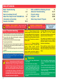
Basic Troubleshooting
Note: If you suspect you have damaged parts, you can follow the
Advanced Troubleshooting procedure on pages 16 and 17 to determine
which ones need replacing.
Basic Troubleshooting 1
Parts List 2, 3
How to Use Snap Circuits
®
4
About Your Snap Circuits
®
SOUND Parts 5-7
Introduction to Electricity 8
Sound in Our World 9-14
DO’s and DON’Ts of Building Circuits 15
Advanced Troubleshooting 16, 17
Project Listings 18, 19
Projects 1 - 188 20-85
Other Snap Circuits
®
Projects 86
WARNING: SHOCK HAZARD - Never connect Snap
Circuits
®
to the electrical outlets in your home in any way!
Table of Contents
WARNING: Always check your wiring
before turning on a circuit. Never leave
a circuit unattended while the batteries
are installed. Never connect additional
batteries or any other power sources to
your circuits. Discard any cracked or
broken parts.
Adult Supervision: Because children’s
abilities vary so much, even with age
groups, adults should exercise
discretion as to which experiments are
suitable and safe (the instructions
should enable supervising adults to
establish the experiment’s
suitability for
the child). Make sure your child reads
and follows all of the relevant
instructions and safety procedures, and
keeps them at hand for reference.
This product is intended for use by
adults and children who have attained
sufficient maturity to read and follow
directions and warnings.
Never modify your parts, as doing so
may disable important safety features in
them, and could put your child at risk of
injury.
WARNING: CHOKING HAZARD -
Small parts. Not for children under 3 years.
!
Conforms to all applicable
U.S. government
requirements.
• Use only 1.5V “AA” type, alkaline batteries
(not included).
• Insert batteries with correct polarity
.
•
Non-rechargeable batteries should not be
recharged. Rechargeable batteries should
only be charged under adult supervision, and
should not be recharged while in the product.
• Do not mix old and new batteries.
• Do not connect batteries or battery holders
in parallel.
• Do not mix alkaline, standard (carbon-
zinc), or rechargeable (nickel-cadmium)
batteries.
• Remove batteries when they are used up.
• Do not short circuit the battery terminals.
• Never throw batteries in a fire or attempt to
open its outer casing.
• Batteries are harmful if swallowed, so keep
away from small children.
Batteries:
!
WARNING: Some projects are intended for use with
headphones (not included in this set). Headphones
performance varies, so you should use caution.
Permanent hearing loss may result from long-term
exposure to sound at high volumes. Start with as
low a volume as possible, then carefully increase to
a comfortable level. Ringing or discomfort in the
ears may indicate that the sound levels are too high;
immediately discontinue using the headphones with
this product and consult a physician.
!

-2-
Important: If any parts are missing or damaged, DO NOT RETURN TO RETAILER. Call toll-free (800) 533-2441 or e-mail us at:
[email protected]. Customer Service • 150 Carpenter Ave. • Wheeling, IL 60090 U.S.A.
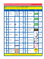
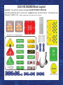
Parts List (Colors and styles may vary) Symbols and Numbers (page 1)
Qty. ID Name Symbol Part # Qty. ID Name Symbol Part #
r 1
Base Grid
(11.0” x 7.7”)
6SCBG
r 1
0.1mF Capacitor 6SCC2
r 3
1-Snap Wire 6SC01
r 1
470mF Capacitor 6SCC5
r 7
2-Snap Wire 6SC02
r 1
1mF Capacitor 6SCC7
r 3
3-Snap Wire 6SC03
r 1
Color Light Emitting
Diode (LED)
6SCD8
r 1
4-Snap Wire 6SC04
r 1
Egg LED Attachment 6SCEGG
r 1
5-Snap Wire 6SC05
r 1
Jumper Wire (black) 6SCJ1
r 1
6-Snap Wire 6SC06
r 1
Jumper Wire (red) 6SCJ2
r 2
Battery Holder - uses
two (2) 1.5V type “AA”
(not included)
6SCB1
r 1
Audio Jack 6SCJA
You may order additional / replacement parts at our website: www.snapcircuits.net
5
4
3
2
1
C2
C7
C5
6
B1
JA
D8

-3-
Important: If any parts are missing or damaged, DO NOT RETURN TO RETAILER. Call toll-free (800) 533-2441 or e-mail us at:
[email protected]. Customer Service • 150 Carpenter Ave. • Wheeling, IL 60090 U.S.A.
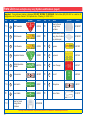
Parts List (Colors and styles may vary) Symbols and Numbers (page 2)
Qty. ID Name Symbol Part # Qty. ID Name Symbol Part #
r 1
NPN Transistor 6SCQ2
r 1
Tube for Sound
Energy Demo
Container
6SCSEDCT
r 1
100W Resistor 6SCR1
r 1
Flexible Sheet for Sound
Energy Demo Container
(may include spare)
6SCSEDCF
r 1
5.1kW Resistor 6SCR3
r 1
Speaker 6SCSP2
r 1
Adjustable Resistor 6SCRV
r 1
Keyboard 6SCU26
r 1
500kW Adjustable
Resistor
6SCRV3
r 1
Voice Changer 6SCU27
r 1
Photoresistor 6SCRP
r 1
Echo IC 6SCU28
r 2
Slide Switch 6SCS1
r 1
Microphone 6SCX1
r 1
Press Switch 6SCS2
r 1
Stereo Cable 9TLSCST
r 1
Base for Sound
Energy Demo
Container
6SCSEDCB
You may order additional / replacement parts at our website: www.snapcircuits.net
U27
SP2
U28
S1
S2
U26
RP
Q2
RV
R3
R1
RV3
X1

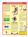
How to Use Snap Circuits
®
Snap Circuits
®
uses building blocks with snaps
to build the different electrical and electronic
circuits in the projects. Each block has a
function: there are switch blocks, light blocks,
battery blocks, different length wire blocks, etc.
These blocks are different colors and have
numbers on them so that you can easily
identify them. The blocks you will be using are
shown as color symbols with level numbers
next to them, allowing you to easily snap them
together to form a circuit.
For Example:
This is the switch block, which is green and has
the marking on it. The part symbols in this
booklet may not exactly match the appearance
of the actual parts, but will clearly identify them.
This is a wire block, which is blue and comes
in different wire lengths.
This one has the number , , , ,
or on it depending on the length of the wire
connection required.
There is also a 1-snap wire that is used as a
spacer or for interconnection between different
layers.
You need a power source to build each circuit.
This is labeled and requires two (2) 1.5V
“AA” batteries (not included).
A large clear plastic base grid is included with
this kit to help keep the circuit blocks properly
spaced. You will see evenly spaced posts that
the different blocks snap into. The base has
rows labeled A-G and columns labeled 1-10.
Next to each part in every circuit drawing is a
small number in black. This tells you which
level the component is placed at. Place all
parts on level 1 first, then all of the parts on
level 2, then all of the parts on level 3, etc.
Some circuits use the jumper wires to make
unusual connections. Just clip them to the
metal snaps or as indicated.
This set contains an egg LED attachment,
which can be mounted on the color LED (D8)
to enhance its light effects.
This set contains a sound energy
demonstration container, which will sometimes
be placed over the speaker. Its use is
explained in project 13.
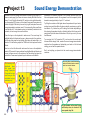
To assemble it, lay the tube and flexible sheet
over the base, and then push the tube into the
base, as shown. Do not disassemble it except
to repair it. This set may include a spare for the
flexible sheet, and household plastic wrap also
works.
S2
2
3 4 5
6
B1
-4-
Egg LED attachment
mounted to D8
Egg
Note: While building the projects, be careful not
to accidentally make a direct connection across
the battery holder (a “short circuit”), as this may
damage and/or quickly drain the batteries.
Sound Energy Demonstration
Container Assembly
(Adult supervision recommended)
Flexible
sheet
Base
Tube

-5-
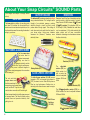
About Your Snap Circuits
®
SOUND Parts
(Part designs are subject to change without
notice).
BASE GRID
The blue snap wires
are wires used to
connect components.
They are used to
transport electricity and do
not affect circuit performance.
They come in different lengths to
allow orderly arrangement of connections
on the base grid.
The red and black
jumper wires make
flexible connections for
times when using the snap wires
would be difficult. They also are
used to make connections off the base grid.
Wires transport electricity just like pipes are used
to transport water. The colorful plastic coating
protects them and prevents electricity from
getting in or out.
BATTERY HOLDER
The base grid is a platform for mounting parts
and wires. It functions like the printed circuit
boards used in most electronic products, or like
how the walls are used for mounting the electrical
wiring in your home.
SNAP WIRES & JUMPER WIRES
The batteries (B1) produce an electrical voltage
using a chemical reaction. This “voltage” can be
thought of as electrical pressure, pushing
electricity through a circuit just like a pump
pushes water through pipes. This voltage is
much lower and much safer than that used in
your house wiring. Using more batteries
increases the “pressure”, therefore, more
electricity flows.
Battery Holder (B1)
SLIDE & PRESS SWITCHES
The slide & press switches (S1 & S2) connect
(pressed or “ON”) or disconnect (not pressed or
“OFF”) the wires in a circuit. When ON they have no
effect on circuit performance. Switches turn on
electricity just like a faucet turns on water from a pipe.
Slide & Press
Switches
(S1 & S2)
RESISTORS
Resistors “resist” the flow of electricity and are
used to control or limit the current in a circuit.
Snap Circuits
®
SOUND includes 100
W
(R1) and
5.1k
W
(R3) resistors (“k” symbolizes 1,000, so
R3 is really 5,100W). Materials like metal have
very low resistance (<1W), while materials like
paper, plastic, and air have near-infinite
resistance. Increasing circuit resistance reduces
the flow of electricity.
Resistors (R1 & R3)
Adjustable Resistor (RV)
The adjustable
resistor (RV) is a
50kW resistor but
with a center tap
that can be adjusted
between 200W and
50kW.
The 500k
W
adjustable resistor (RV3) is a
500kW resistor that can be adjusted between
200W and 500kW.
500k
W
Adjustable Resistor (RV3)

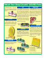
About Your Snap Circuits
®
SOUND Parts
LED
-6-
The speaker (SP) converts electricity into sound
by making mechanical vibrations. These
vibrations create variations in air pressure, which
travel across the room. You “hear” sound when
your ears feel these air pressure variations.
SPEAKER
Speaker (SP2)
Color LED
(D8)
The color LED (D8) is a light emitting diode, and
may be thought of as a special one-way light
bulb. In the “forward” direction, (indicated by the
“arrow” in the symbol) electricity flows if the
voltage exceeds a turn-on threshold (about 1.5V
for red, about 2.0V for green, and about 3.0V for
blue); brightness then increases. The color LED
contains red, green, and blue LEDs, with a micro-
circuit controlling then. A high current will burn
out an LED, so the current must be limited by
other components in the circuit. LED’s block
electricity in the “reverse” direction.
CAPACITOR
The 0.1
m
F, 1
m
F, and 470
m
F capacitors (C2, C7,
& C5) can store electrical pressure (voltage) for
periods of time. This storage ability allows them
to block stable voltage signals and pass
changing ones. Capacitors are used for filtering
and delay circuits.
Microphone (X1)
The microphone (X1) is actually a resistor that
changes in value when changes in air pressure
(sounds) apply pressure to its surface.
MICROPHONE
The photoresistor (RP) is a light-sensitive
resistor, its value changes from nearly infinite in
total darkness to about 1000W when a bright light
shines on it.
Photoresistor (RP)
Capacitors (C2, C5, & C7)
TRANSISTORS
ELECTRONIC MODULES
The NPN transistor (Q2) is a component that
uses a small electric current to control a large
current, and is used in switching, amplifier, and
buffering applications. Transistors are easy to
miniaturize, and are the main building blocks of
integrated circuits including the microprocessor
and memory circuits in computers.
The keyboard (U26) contains resistors,
capacitors, switches, and an integrated circuit. It
can produce two adjustable audio tones at the
same time. The tones approximate musical
notes, and may not be exact. The tone of the
green keys can be adjusted with the tune knob
or using external resistors and capacitors. A
schematic for it is available at
www.snapcircuits.net/faq.
Connections:
(+) - power from batteries
RES - resistor freq adjust
CAP - capacitor freq adjust
OUT - output connection
(–) - power return to batteries
See projects 1, 6, & 25 for example of proper connections.
NPN Transistor (Q2)
Keyboard (U26)

-7-
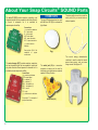
About Your Snap Circuits
®
SOUND Parts
Audio Jack (JA)
OTHER PARTS
The stereo cable is used to connect the
audio jack (JA) to your music device or
external speaker.
The audio jack (JA) is a connector
mounted on snaps, and is used for
interfacing your music device or external
speaker to Snap Circuits
®
.
The egg LED attachment can be used
with the color LED (D8) to enhance the
light effects.
Egg
The sound energy demonstration
container is used to show that sound
waves have energy, and can move
things around. See project 13.
Connections:
(+) - power from batteries
SPD - speed adjust
SP+ - speaker (+)
SP– - speaker (–)
MIC+ - microphone (+)
MIC– - microphone (–)
REC - record
PLY - play
(–) - power return to batteries
See project 7 for example of
proper connections.
The voice changer (U27) contains resistors, capacitors,
and an integrated circuit that are needed to record and
play back sound at different speeds. A schematic for it is
available at www.snapcircuits.net/faq.
Connections:
(+) - power from batteries
G+ - gain control
G– - gain control
ADJ - echo adjust
INP - input connection
OUT - output connection
(–) - power return to
batteries
See projects 10 & 41 for
examples of proper
connections.
The echo IC (U28) contains resistors, capacitors, and
integrated circuits that are needed to add echo effects to
a sound. A schematic for it is available at
www.snapcircuits.net/faq.

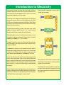
Introduction to Electricity
What is electricity? Nobody really knows. We only know how to produce it,
understand its properties, and how to control it. Electricity is the movement of sub-
atomic charged particles (called electrons) through a material due to electrical
pressure across the material, such as from a battery.
Power sources, such as batteries, push electricity through a circuit, like a pump
pushes water through pipes. Wires carry electricity, like pipes carry water. Devices
like LEDs, motors, and speakers use the energy in electricity to do things. Switches
and transistors control the flow of electricity like valves and faucets control water.
Resistors limit the flow of electricity.
The electrical pressure exerted by a battery or other power source is called
voltage and is measured in volts (V). Notice the “+” and “–” signs on the battery;
these indicate which direction the battery will “pump” the electricity.
The electric current is a measure of how fast electricity is flowing in a wire, just
as the water current describes how fast water is flowing in a pipe. It is expressed
in amperes (A) or milliamps (mA, 1/1,000 of an ampere).
The “power” of electricity is a measure of how fast energy is moving through a
wire. It is a combination of the voltage and current (Power = Voltage x Current). It
is expressed in watts (W).
The resistance of a component or circuit represents how much it resists the
electrical pressure (voltage) and limits the flow of electric current. The relationship
is Voltage = Current x Resistance. When the resistance increases, less current
flows. Resistance is measured in ohms (W), or kilo ohms (kW, 1,000 ohms).
Nearly all of the electricity used in our world is produced at enormous generators
driven by steam or water pressure. Wires are used to efficiently transport this
energy to homes and businesses where it is used. Motors convert the electricity
back into mechanical form to drive machinery and appliances. The most important
aspect of electricity in our society is that it allows energy to be easily transported
over distances.
Note that “distances” includes not just large distances but also tiny distances. Try
to imagine a plumbing structure of the same complexity as the circuitry inside a
portable radio - it would have to be large because we can’t make water pipes so
small. Electricity allows complex designs to be made very small.
There are two ways of arranging parts in a circuit, in series or
in parallel. Here are examples:
Placing components in series increases the resistance; highest
value dominates. Placing components in parallel decreases the
resistance; lower value dominates.
The parts within these series and parallel sub-circuits may be
arranged in different ways without changing what the circuit
does. Large circuits are made of combinations of smaller series
and parallel circuits.
Series Circuit
Parallel Circuit
-8-

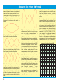
Sound in Our World
Sound is a variation in air pressure created by
a mechanical vibration. See projects 13 & 51
for a demonstration of this. These air pressure
variations travel across the room like waves,
so we call them sound waves. You “hear”
sound when your ears feel these air pressure
variations, and convert them to nerve pulses
that your brain interprets. Eventually the
energy of a sound wave is absorbed, and
becomes heat.
Sound waves can also be thought of as waves
of temporary compression that travel through
materials. Notice that at a loud concert you can
sometimes feel the pressure waves, in
addition to hearing them. Sound waves can
travel through liquids and solids but their
speed may change and their energy may be
reduced, depending on the characteristics of
the material. Sound waves can only travel
through a compressible material, and so
cannot travel through a vacuum. Outer space
is silent, because there is no air or other
material for sound waves to travel through.
The “hearing” part of your ear is inside your
skull; the flaps you see are just funnels to
collect the sound and pass it along to your
eardrum inside. When you were young your
brain learned to interpret the difference in the
information collected from your two ears, and
use it to know which direction a sound came
from. If one of your ears is clogged, then it is
difficult to determine a sound’s direction.
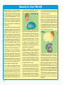
You can compare sound waves from your
voice to waves in a pond. When you speak,
the movements in your mouth create sound
waves just as tossing a rock into the pond
creates water waves. Sound waves travel
through air as water waves travel across the
pond. If someone is nearby, then their ears will
feel the air pressure variations caused by your
sound waves just as a small boat at the other
side of the pond will feel the water waves.
If the mechanical vibration causing the sound
wave occurs at a constant rate, then the sound
wave will repeat itself at the same rate; we
refer to this as the frequency of the sound
wave. Nearly all sound waves have their
energy spread unevenly across a range of
frequencies. When you say a word, you create
a sound wave with energy at various
frequencies, just as tossing a handful of
various-sized rocks into the pond will create a
complicated water wave pattern.
Frequency measures how many times
something occurs per second, expressed in
units called hertz (Hz). The metric prefixes can
be used, so 1,000 repetitions per second is 1
kilohertz (kHz) and 1,000,000 repetitions per
second is 1 megahertz (MHz). The range of
frequencies that can be heard by the human
ear is approximately 20 to 20,000 Hz and is
referred to as the audio range.
Just as there are sound waves caused by
mechanical vibrations, there are also electrical
waves caused by electrical variations. Just as
sound waves travel through air, electrical
waves travel through wires. A microphone
senses pressure variations from sound waves
and creates electrical waves at the same
frequencies. A speaker converts electricity into
sound, by using the energy in electrical waves
to create mechanical vibrations (sound waves)
at the same frequencies.
How does the speaker make sound? An
electric current flowing through a wire has a
very, very tiny magnetic field. Inside the
speaker is a coil of wire and a magnet. The coil
of wire concentrates the magnetic field from
the flowing electric current, enough to make
the magnet move slightly, like a vibration. The
magnet’s vibration creates the air pressure
variations that travel to your ears.
Your speaker can only create sound from a
CHANGING electrical signal, for unchanging
electrical signals it acts like a 32 ohm resistor.
(An unchanging signal does not cause the
magnet in the speaker to move, so no sound
waves are created). Electrical variations at
high frequencies (referred to as radio
frequencies) cannot be heard by your ears, but
can be used to create electromagnetic radio
waves, which travel through air and are used
for many forms of communication. In AM and
FM radio, voice or music is superimposed on
radio waves, allowing it to be transmitted over
great distances, to later be decoded and
listened to.
-9-
Sound and water waves
Speaker
sound waves

Sound in Our World
In stereo, sound is produced on several
speakers (or earphones) with varying
frequencies/loudness on each. This gives the
impression that the sound is coming from
different directions, and is more pleasing to
listen to. Mono sound is the same on all
speakers, and is easier to produce. Note that
a “stereo speaker” can be several speakers
(possibly of different sizes) in one package.
Your Snap Circuits
®
speaker (SP2) is a mono
speaker. Surround sound is a technique for
placing several speakers (with different
sounds from each) around the listener, to
create a more interesting listening experience.
The loudness of sound waves is a measure of
the pressure level, and is expressed in
decibels (dB, a logarithmic scale). Long-term
exposure to loud sounds can lead to hearing
loss. Here are some examples of sound levels:
Sound waves travel very fast, but sometimes
you can perceive the effects of their speed.
Ever notice how sometimes you see lightning
before you hear the thunder? The reason is
because light travels at about 186,000 miles
per second, while sound travels at only about
1,100 feet per second in air. Sound can travel
through liquids and solids, but with increased
speed (the speed depends on the material’s
compressibility and density). Sound travels 4.3
times faster in water than in air; this difference
in speed confuses our ears, making it difficult
to perceive the direction of sound while
underwater.
A sonic boom is a shock wave that occurs
when an object travels through air at
supersonic speeds (faster than the speed of
sound). These sonic shock waves are similar
to how the bow of a boat produces waves in
the water. Sonic shock waves can carry a lot
of sound energy and can be very unpleasant
to hear, like an explosion. Aircraft can fly at
supersonic speeds, and the sonic boom
produced is so unpleasant that aircraft are
rarely permitted to fly at supersonic speeds
over populated areas.
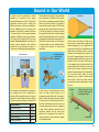
Sound waves can reflect off walls and go
around corners, though their energy may be
reduced depending on the angle and the
roughness of the surface. Sometimes sound
waves can be channeled to focus in a certain
direction. As an example, get a long tube, like
the ones for wrapping paper. Use one of the
projects that make a continuous tone, such as
projects 6 or 92. Hold one end of the tube next
to the speaker (use the yellow side with the
grating) and the other end near your ear, then
remove the tube and compare the sound
volume at the same distance from the speaker.
The long tube should make the sound
reaching your ear louder, because sound
waves reflect off the tube walls and stay
concentrated, instead of spreading out across
the room.
-10-
Sound Source Level
Threshold of pain 130dB
Chain saw 110dB
Normal conversation 50dB
Calm breathing 10dB
Hearing threshold 0dB
Surround sound
Sonic boom
It’s hard to perceive
sound direction
underwater.
Placing a long tube next to
the speaker keeps its sound
waves together longer.
Sound waves
Long tube
Speaker

Sound in Our World
Some of a sound wave’s energy can reflect off
walls or objects and come back to you.
Normally you don’t notice these reflections
when you are speaking because not all of the
energy is reflected, and the delay is so short
that your ears can’t distinguish it from the
original sound, but sometimes (such as in a
very large open room) you can hear them -
these are echoes! You hear an echo when a
lot of the energy of your voice is reflected back
to you after a noticeable delay. The delay time
is the distance (to the reflection point and
back) divided by the speed of sound. Most
people cannot distinguish reflected sound
waves with delays of less than 1/15 of a
second, and perceive them as being part of
the original sound. Echoes can be simulated
electronically by replaying a recorded sound
with a small delay and at reduced volume. See
project 10 and others for examples.
In project 10, if your speaker is too close to
your microphone then the echo sound can be
picked up by the microphone and echoed
again and again until you can’t hear anything
else. The same thing can occur in telephone
systems, and these systems sometimes have
echo-cancelling circuitry to prevent problems
(especially in overseas calls, where the
transmission delay times may be longer).
Engineers developing sensitive audio
equipment need to make very accurate sound
measurements. They need rooms that are
sealed from outside sounds, and need to
minimize the measured signal’s reflections off
the walls/ceiling/floor. Specialized rooms have
been designed for this, called anechoic
chambers. These chambers are virtually
soundproof and have specially shaped
materials (usually made of foam) on the walls
to absorb sound waves without producing any
echoes. These chambers simulate a quiet,
open space, allowing the engineers to
accurately measure the equipment being
tested.
Everything has a natural frequency, its
resonance frequency, at which it will vibrate
more easily. When sound waves strike an
object at its natural frequency, the object can
absorb and store significantly more energy
from the sound waves, as vibration. To help
understand this concept, think of a playground
swing, which tends to always swing back and
forth at the same rate. If you push the swing at
the ideal moment, it will absorb energy from
you and swing higher. You don’t need to push
the swing very hard to make it go high, you just
need to keep adding energy at the right
moment. In project 13 (Sound Energy
Demonstration), the frequency is tuned to the
speaker’s natural frequency, making it vibrate
noticeably.
Resonance is an important consideration in
the design of musical instruments, and also in
construction. If high winds blow on a tall
building or a bridge at the structure’s resonant
frequency, vibrations can slowly increase until
the structure is torn apart and collapses.
A cone can help you project your voice. A cone
keeps the sound waves (air pressure
variations) together longer, so they don’t
spread out so quickly. Long ago, people who
had trouble hearing used an ear trumpet,
which helps collect sound waves. A person
would speak into the wide end of the ear
trumpet, and the trumpet makes the sound
louder at the listening person’s ear. Electronic
hearing aids have replaced ear trumpets.
Doctors use a stethoscope to hear inside
patient’s bodies. A stethoscope uses a cone-
like structure to collect sound waves; then
passes them into the doctor’s ear.
-11-
Sound waves reflecting off a wall
Anechoic chamber
Small pushes at the right
moment will make the swing
go higher.

Sound in Our World
Electronically we amplify sound by converting
the sound waves into an electrical signal,
amplify the electrical signal, and then convert
that back to sound waves.
There are many other applications for sound
waves. Here are some examples:
In SONAR (short for SOund Navigation And
Ranging), sound waves are sent out underwater
at various frequencies and the echoes are
measured; the distance to any objects can be
determined using the time for the echoes to
arrive, and the speed of sound. SONAR is used
for navigating around underwater obstacles and
for detecting other ships, especially submarines.
SONAR is also used by the fishing industry to
help find and harvest fish. Sound waves can
also be used to determine the depth of an oil
well. RADAR (RAdio Detection And Ranging) is
similar to SONAR but uses radio waves instead
of sound waves.
Ultrasound waves are above 20 kHz, beyond
the range of human hearing. Bats use
ultrasound waves to effectively “see” in the
dark. Ultrasound waves are also used in
medical imaging, to create pictures of muscles
and organs in the human body. Ultrasound
waves are sometimes used in cleaning items
like jewelry.
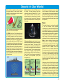
Ultrasonic welding is used in industry to bond
materials (usually plastics) together using high
frequency sound waves. The energy of the
sound waves is concentrated at the points to
be bonded, and basically melts the material at
the contact points. This can create a strong
bond, without using glue or nails. Ultrasonic
welding has been used to bond the bottoms of
Snap Circuits
®
parts in the past, and might still
be used for the speaker (SP2) and
microphone (X1).
Earthquakes are compression waves, similar
to sound waves but with enormous power.
Using triangulation from several measurement
points, and knowing how fast these waves can
travel across the earth’s surface, scientists can
determine where the earthquake began (called
the epicenter).
Music
The subject of music is one where the worlds
of art and science come together.
Unfortunately, the artistic/musician field works
with qualities that depend on our feelings and
so are difficult to express using numbers while
science/engineering works with the opposite -
clearly defined, measurable qualities. As a
result, some of the terms used may seem
confusing at first, but you will get used to them.
Music is when vibrations (creating sound
waves) occur in an orderly and controlled
manner forming a pattern with their energy
concentrated at specific frequencies, usually
pleasant to listen to. Noise is when the
vibrations occur in an irregular manner with
their energy spread across a wide range of
frequencies, usually annoying to hear (static
on a radio is a good example). Notice how
some people refer to music that they don’t like
as noise. In electrical systems, noise is
undesired interference that can obscure the
signal of interest.
Another way to think of this is that the ear tries
to estimate the next sounds it will hear. Music
with a beat, a rhythm, and familiar instruments
can be thought of as very predictable, so we
find it pleasant to listen to. Notice also that we
always prefer familiar songs to music that we
are hearing for the first time. Sudden, loud,
unpredictable sounds (such as gunfire, a glass
breaking, or an alarm clock) are very
-12-
Cone
Ear Trumpet Stethoscope
Horn
Anvil or jig
Plastic
parts
Phase 1 Phase 2 Phase 3
Pressure is applied
by the horn.
The horn vibrates
the plastic parts
very quickly.
The plastic parts
melt together from
the friction created.
SONAR
Ultrasonic welding
Ultrasound photo of a heart (echocardiogram)

Sound in Our World
unnerving and unpleasant. Most electronic
speech processing systems being developed
use some form of speech prediction filters.
Take a piece of string or rope roughly 4 feet
long and tie one end of it to a chair or other
piece of furniture. Swing the other end up and
down so that you have a cyclic pattern, as
shown:
Now swing it three times as fast (three times
the frequency), to produce this pattern:
Now try to swing it five times as fast (five times
the frequency), to produce this pattern:
Since the later patterns are frequency
multiples of the first, we refer to them as
overtones (the music term) or harmonics (the
electronics term) and the original pattern is
called the fundamental. If you could combine
all three of the above patterns onto the string
then you would get a pattern, which looks like
this:
This combined pattern (a single fundamental
with overtones) is called a tone (and a pure
tone is a single fundamental with no
overtones). Notice that each pattern is more
difficult to produce than the one before it, with
the combined pattern being quite complicated.
And also notice that the more complicated
patterns are much more interesting and
pleasing to look at than the simpler ones. Well
the same thing applies to sound waves.
Complex patterns that have many overtones
for each fundamental are more pleasant to
listen to than simple patterns. If many
overtones were combined together, the results
would approximate a square wave shape.
All traditional music instruments use this
principle, with the instrument shapes and
materials perfected through the years to
produce many overtones for each fundamental
chord or key that is played by the user. Grand
pianos sound better than upright pianos since
their larger shape enables them to produce
more overtones, especially at lower
frequencies. Concert halls sound better than
small rooms because they are designed for
best overtone performance and to take
advantage of the fact that sound waves can
reflect off walls to produce different overtone
relationships between both of your ears. The
same thing applies to stereo sound. You may
have heard the term acoustics; this is the
science of designing rooms for best sound
effects.
A commonly used musical scale (which
measures pitch) will now be introduced. This
scale is called the equal temperament scale,
expressed in hertz. You might think of this as
a conversion table between the artistic and
scientific worlds since it expresses pitch in
terms of frequency. Each overtone (overtone
0 being the fundamental) is divided into 12
semitones: C, C# (“C-flat”), D, D#, E, F, F#, G,
G#, A, A#, and B. The semitones increase by
the ratio 12:2, or 1.05946. Musical notes
(tones) are the measure of pitch and are
expressed using both the semitone and the
overtone, such as A3, G#4, D6, A#1, and E2.
(frequency in hertz and rounded off)
-13-
Overtone
C C# D D# E F
0 16.4 17.3 18.4 19.4 20.6 21.8
1 32.7 34.6 36.7 38.9 41.2 45.7
2 65.4 69.3 73.4 77.8 82.4 87.3
3 130 139 147 156 165 175
4 262 278 294 311 330 349
5 523 554 587 622 659 698
6 1047 1109 1174 1245 1319 1397
7 2093 2217 2344 2489 2637 2794
8 4186 4435 4698 4978 5274 5588
9 8372 8870 9397 9956 10548 11175
Overtone
F# G G# A A# B
0 23.1 24.5 26.0 27.5 29.1 30.9
1 46.2 49.0 51.9 55.0 58.3 61.7
2 92.5 98.0 104 110 117 123
3 185 196 208 220 233 247
4 370 392 415 440 466 494
5 740 784 831 880 932 988
6 1480 1568 1661 1760 1865 1976
7 2960 3136 3322 3520 3729 3951
8 5920 6271 6645 7040 7459 7902
9 11840 12542 13290 14080 14917 15804

Sound in Our World
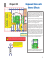
On your U26 keyboard, the blue keys
approximate the 5th overtone notes, and the
green keys approximate the 6th overtone
notes; actual frequency may vary from the
musical scale. The tone of the green keys can
be adjusted with the tune knob, allowing them
to be in tune with the blue keys, or out of tune
with them. The tone of the green keys may
also be adjusted using external resistors and
capacitors, which can change the frequency
range dramatically (and even beyond the
hearing range of your ears), and can create an
optical theremin. Your keyboard can play one
blue note and one green note at the same
time; if you press two keys of the same color
at the same time, only the higher note will be
played. Projects 1-4 and 25-27 demonstrate
the capabilities of the U26 keyboard.
On most instruments, when you play a note
the sound produced is initially loud and then
decreases with time. On your U26 keyboard,
a note ends when you release the key, unless
you connected external resistors to produce a
continuous tone. More complex electronic
instruments can simulate more notes at the
same time, have more advanced techniques
for producing overtones, and continue to play
the note with decreasing loudness after the
key has been released.
The musical world’s equivalent to frequency
is pitch. The higher the frequency, the higher
the pitch of the sound. Frequencies above
2,000 Hz can be considered to provide treble
tone. Frequencies about 300 Hz and below
provide bass tone.
Up to now, the musical measures of pitch and
loudness have been discussed. But many
musical sounds have the same pitch and
loudness and yet sound very different. For
example, the sound of a guitar compared to
that of a piano for the same musical note. The
difference is a quality known as timbre. Timbre
describes how a sound is perceived, its
roughness. Scientifically it is due to differences
in the levels of the various overtones, and so
cannot be expressed using a single number.
Now consider the following two tones, which
differ slightly in frequency:
If they are played at the same time then their
sound waves would be added together to
produce:
Notice that the combined wave has a regular
pattern of where the two tones add together
and where they cancel each other out. This is
the effect that produces the beat you hear in
music. Two tones (that are close in frequency
and have similar amplitude for their
fundamental and for each of their overtones)
will beat at the rate of their frequency
difference. Rhythm is the pattern of regular
beat that a song has.
Now observe this tone:
The frequency is slowly increasing and
decreasing in a regular pattern. This is an
example of vibrato. If the frequency is
changing slowly then it will sound like a varying
pitch; a fast vibrato (several times a second)
produces an interesting sound effect. The
alarm IC (U2, included in Snap Circuits
®
models SC-100, 300, 500, or 750) produces
sounds using the vibrato effect.
Tempo is a musical term, which simply
describes how quickly a song is played.
-14-

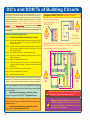
DO’s and DON’Ts of Building Circuits
After building the circuits given in this booklet, you may wish to experiment on your own.
Use the projects in this booklet as a guide, as many important design concepts are
introduced throughout them. Every circuit will include a power source (the batteries), a
resistance (which might be a resistor, capacitor, speaker, integrated circuit, etc.), and wiring
paths between them and back. You must be careful not to create “short circuits” (very low-
resistance paths across the batteries, see examples at right) as this will damage
components and/or quickly drain your batteries. Only connect the keyboard (U26), voice
changer (U27), and echo IC (U28) using configurations given in the projects, incorrectly
doing so may damage them. ELENCO
®
is not responsible for parts damaged due to
incorrect wiring.
Here are some important guidelines:
ALWAYS USE EYE PROTECTION WHEN EXPERIMENTING ON YOUR OWN.
ALWAYS include at least one component that will limit the current through a circuit, such
as the speaker, capacitors, ICs (which must be connected properly),
microphone, or resistors.
ALWAYS use LEDs, transistors, and switches in conjunction with other components that
will limit the current through them. Failure to do so will create a short circuit
and/or damage those parts.
ALWAYS connect capacitors so that the “+” side gets the higher voltage.
ALWAYS disconnect your batteries immediately and check your wiring if something
appears to be getting hot.
ALWAYS check your wiring before turning on a circuit.
ALWAYS connect the keyboard (U26), voice changer (U27), and echo IC (U28) using
configurations given in the projects or as per the connection description on
pages 6 and 7.
NEVER connect to an electrical outlet in your home in any way.
NEVER leave a circuit unattended when it is turned on.
NEVER use headphones at high sound levels.
For all of the projects given in this book, the parts may be arranged in different
ways without
changing the circuit. For example, the order of parts connected in series or in parallel does
not matter — what matters is how combinations of these sub-circuits are arranged together.
Placing a 3-snap wire directly
across the batteries is a
SHORT CIRCUIT.
This is also a
SHORT CIRCUIT.
When the slide switch (S1) is turned on, this large circuit has a SHORT
CIRCUIT path (as shown by the arrows). The short circuit prevents any
other portions of the circuit from ever working.
NEVER
DO!
NEVER
DO!
NEVER
DO!
Examples of SHORT CIRCUITS - NEVER DO THESE!!!
Warning to Snap Circuits
®
owners: Do not connect
additional voltage sources from other sets, or you
may damage your parts. Contact Elenco
®
if you have
questions or need guidance.
You are encouraged to tell us about new programs and circuits you
create. If they are unique, we will post them with your name and state
on our website at:
www.snapcircuits.net/learning_center/kids_creation
Send your suggestions to ELENCO
®
ELENCO
®
provides a circuit designer so that you can make your own
Snap Circuits
®
drawings. This Microsoft
®
Word document can be
downloaded from:
www.snapcircuits.net/learning_center/kids_creation
or through the www.snapcircuits.net website.
WARNING: SHOCK HAZARD - Never connect Snap Circuits
®
to the electrical outlets in your home in any way!
!
!
!
NEVER
DO!
!
!
!
-15-

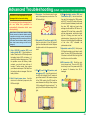
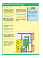
Advanced Troubleshooting
(Adult supervision recommended)
ELENCO
®
is not responsible for parts
damaged due to incorrect wiring.
If you suspect you have damaged parts,
you can follow this procedure to
systematically determine which ones
need replacing:
(Note: Some of these tests connect an LED
directly across the batteries without another
component to limit the current. Normally this
might damage the LED, however Snap Circuits
®
LEDs have internal resistors added to protect
them from incorrect wiring, and will not be
damaged.)
1. Color LED (D8), speaker (SP2), and
battery holder (B1): Place batteries in
holder. Place the color LED directly across
the battery holder (LED + to battery +), it
should light and be changing colors. “Tap”
the speaker across the battery holder
contacts; you should hear static as it
touches. If neither works, then replace
your batteries and repeat. If still bad, then
the battery holder is damaged. Test both
battery holders.
2. Red & black jumper wires: Use this
mini-circuit to test each jumper wire; the
LED should light.
3. Snap wires: Use this mini-circuit to test
each of the snap wires, one at a time. The
LED should light.
4. Slide
switch (S1) and Press switch (S2):
Use this mini-circuit; if the LED doesn’t
light then the slide switch is bad. Replace
the slide switch with the press switch to
test it.
5. 100
W
(R1) and 5.1k
W
(R3) resistors, and
microphone (X1): Use this mini-circuit;
the LED will be bright if the R1 resistor is
good. Next use the 5.1kW resistor in place
of the 100W resistor; the LED should be
much dimmer but still light. Next, replace
5.1kW resistor with the microphone (“+” to
right); the LED should flicker dimly but still
light.
6. 500k
W
adjustable resistor (R
V3) and
Photoresistor (RP): Use the mini-circuit
from test 5 but replace the 100W resistor
with RV3.
Turning RV3’s knob all the way
to the left (counter-clockwise) should make
the color LED bright and most other
settings should make the LED dim or off;
otherwise RV3 is bad. Next, replace RV3
with the photoresistor, and shine a bright
light on it. Waving your hand over the
phototransistor (changing the light that
shines on it) should change the brightness
of the color LED; otherwise the
photoresistor is bad.
7. Adjustable resistor (RV): Build project
98. Move the resistor control lever to both
sides. The
color LED (D8) should be bright
if the lever is to the far left or far right, and
dim if the lever is in the middle.
8. NPN transistor (Q2): Build the mini-
circuit shown here. The
color LED (D8)
should only be on if the press switch (S2)
is pressed. If otherwise, then Q2 is
damaged.
-16-
1

Advanced Troubleshooting
(Adult supervision recommended)
9. Keyboard (U26): Build project 92, but
omit the 0.1mF capacitor (C2) and the
5.1kW resistor (R3). You should hear a
tone when you press any key. Turning the
TUNE knob while pressing any green key
should change the tone slightly. Now add
R3 to the circuit, and you should hear a
continuous tone. If any of this does not
work then the keyboard is damaged.
10. 0.1
m
F (C2), 1
m
F (C7), and 470
m
F (C5)
capacitors: Build project 92; removing
C2 from it should change the tone, or C2
is damaged. Next, replace C2 with C7; the
pitch of the tone should be lower now
,
or
C7 is damaged. Next, replace C7 with C5;
you should hear a click every few seconds,
or C5 is damaged.
11. Voice changer (U27): Build project 7.
Follow the project’s
instructions to confirm
that you can make a recording and play it
back at different speeds.
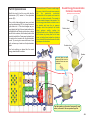
12. Echo IC (U28): Build the circuit shown at
right, turn it on, and set the knob on the
500kW adjustable resistor (RV3)
to the
right. Press any keys on the keyboard; you
should hear tones with echo, and be able
to adjust echo level using the lever on the
adjustable resistor (RV). Removing the
1mF capacitor (C7) should reduce the
volume a little. Sometimes an echo IC
problem can be fixed by turning the circuit
off and back on to reset it.
12. Audio Jack (JA) and stereo cable: If
you have headphones, use them to test
the audio jack using project 14. If you have
a music device, use it to test the audio jack
using project 66. Use project 66 to test
your stereo cable.
13. Sound energy demonstration container:
If the flexible sheet is damaged,
disassemble the container and replace the
flexible sheet; this set may have included
a spare for it, or you can use household
plastic wrap.
ELENCO
®
150 Carpenter Avenue
Wheeling, IL 60090 U.S.A.
Phone: (847) 541-3800
Fax: (847) 520-0085
e-mail: [email protected]
Website: www.elenco.com
You may order additional / replacement
parts at: www.snapcircuits.net
-17-

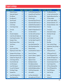
Project # Description Page #
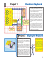
1 Electronic Keyboard 20
2 Aligning the Keyboard 20
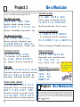
3 Be a Musician 21
4 Be a Musician (II) 21
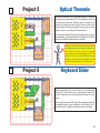
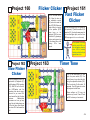
5 Optical Theremin 22
6 Keyboard Slider 22
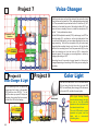
7 Voice Changer 23
8 Voice Changer & Light 23
9 Color Light 23
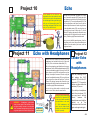
10 Echo 24
11 Echo with Headphones 24
12 Louder Echo with Headphones 24
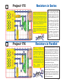
13
Sound Energy Demonstration
25,26
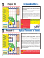
14 Keyboard in Stereo 27
15 Optical Theremin in Stereo 27
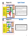
16 Light & Sound 28
17 See Saw 28
18 Light, Sound, & Motion 29
19 Brighter Light, Sound, & Motion 29
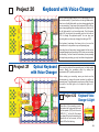
20 Keyboard with Voice Changer 30
21
Optical Keyboard with Voice Changer
30
22
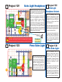
Keyboard Voice Changer & Light
30
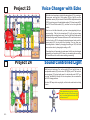
23 Voice Changer with Echo 31
24 Sound Controlled Light 31
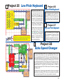
25 Low Pitch Keyboard 32
26 Lower Pitch Keyboard 32
27 Very Low Pitch Keyboard 32
28 Echo Speed Changer 32
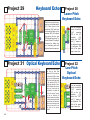
29 Keyboard Echo 33
30 Lower Pitch Keyboard Echo 33
31 Optical Keyboard Echo 33
Project # Description Page #
32
Low Pitch Optical Keyboard Echo
33
33
Keyboard Echo with Stereo Effects
34
34 Optical Echo in Stereo 35
35 Color Short Light 35
36 Keyboard with Optical Theremin 36
37
Keyboard with Optical Theremin (II)
36
38
Adjustable Dual Range Keyboard
36
39
Adjustable Dual Range Keyboard (II)
36
40
Adjustable Dual Range Keyboard (III)
36
41 Your Music with Echo 37
42 Your Music with Echo and Light 37
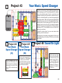
43 Your Music Speed Changer 38
44 Your Music Speed Changer (II) 38
45 Your Music Speed Changer (III) 38
46 Sound On Light 38
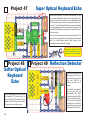
47 Super Optical Keyboard Echo 39
48 Softer Optical Keyboard Echo 39
49 Reflection Detector 39
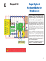
50
Super Optical Keyboard Echo for Headphones
40
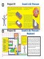
51 Sound is Air Pressure 41
52
Sound is Air Pressure - Keyboard
41
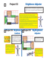
53 Brightness Adjuster 42
54 Brightness Limiters 42
55 Big Brightness Adjuster 42
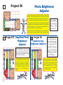
56 Photo Brightness Adjuster 43
57
Amplified Photo Brightness Adjuster
43
58
Amplified Big Brightness Adjuster
43
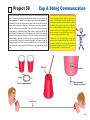
59 Cup & String Communication 44
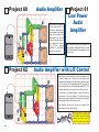
60 Audio Amplifier 45
61 Low Power Audio Amplifier 45
62 Audio Amplifier with L/R Control 45
Project # Description Page #
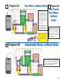
63 Your Music without Echo 46
64
Low Power Your Music without Echo
46
65 Adjustable Music without Echo 46
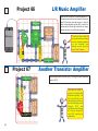
66 L/R Music Amplifier 47
67 Another Transistor Amplifier 47
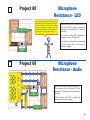
68 Microphone Resistance - LED 48
69 Microphone Resistance - Audio 48
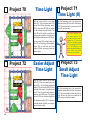
70 Time Light 49
71 Time Light (II) 49
72 Easier Adjust Time Light 49
73 Small Adjust Time Light 49
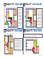
74 Day Light 50
75 Lower Day Light 50
76 Dark Light 50
77 Blow Noise 50
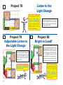
78 Listen to the Light Change 51
79
Adjustable Listen to the Light Change
51
80 Bright or Loud? 51
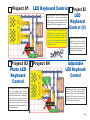
81 LED Keyboard Control 52
82 LED Keyboard Control (II) 52
83 Photo LED Keyboard Control 52
84
Adjustable LED Keyboard Control
52
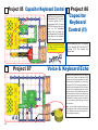
85 Capacitor Keyboard Control 53
86 Capacitor Keyboard Control (II) 53
87 Voice & Keyboard Echo 53
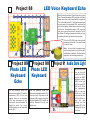
88 LED Voice & Keyboard Echo 54
89 Photo LED Keyboard Echo 54
90 Photo LED Keyboard 54
91 Audio Dark Light 54
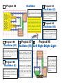
92 Oscillator 55
93 Oscillator (II) 55
Project Listings
-18-

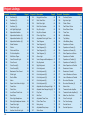
Project # Description Page #
94 Oscillator (III) 55
95 Oscillator (IV) 55
96 Oscillator (V) 55
97 Oscillator (VI) 55
98 Left Right Bright Light 55
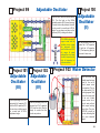
99 Adjustable Oscillator 56
100 Adjustable Oscillator (II) 56
101 Adjustable Oscillator (III) 56
102 Adjustable Oscillator (IV) 56
103 Water Detector 56
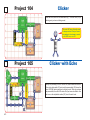
104 Clicker 57
105 Clicker with Echo 57
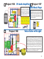
106 3V Audio Amplifier 58
107 Mini Music Player 58
108 Voice Echo with Light 58
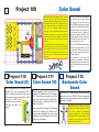
109 Color Sound 59
110 Color Sound (II) 59
111 Color Sound (III) 59
112 Backwards Color Sound 59
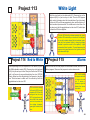
113 White Light 60
114 Red to White 60
115 Alarm 60
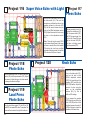
116 Super Voice Echo with Light 61
117 Press Echo 61
118 Photo Echo 61
119 Loud Press Photo Echo 61
120 Knob Echo 61
121 Echo Light Headphone 62
122
Echo Light Headphone Variants
62
123 Press Echo Light 62
124 Photo Echo Light 62
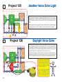
125 Another Voice Echo Light 63
Project # Description Page #
126 Daylight Voice Echo 63
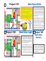
127 Dark V
oice Echo 64
128 Dark Echo Light 64
129 Dark Echo Variants 64
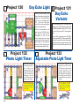
130 Day Echo Light 65
131 Day Echo Variants 65
132 Photo Light Timer 65
133 Adjustable Photo Light Timer 65
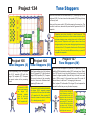
134 Tone Stoppers 66
135 Tone Stoppers (II) 66
136 Tone Stoppers (III) 66
137 Tone Stoppers (IV) 66
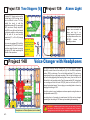
138 Tone Stoppers (V) 67
139 Alarm Light 67
140
Voice Changer with Headphones
67
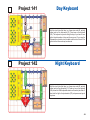
141 Day Keyboard 68
142 Night Keyboard 68
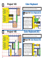
143 Color Keyboard 69
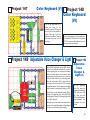
144 Color Keyboard (II) 69
145 Color Keyboard (III) 69
146 Color Keyboard (IV) 69
147 Color Keyboard (V) 70
148 Color Keyboard (VI) 70
149
Adjustable Voice Changer & Light
70
150
Adjustable Voice Changer & Light (II)
70
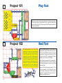
151 Play Fast 71
152 Red First 71
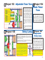
153 Adjustable Timer Tone 72
154 Photo Timer Tone 72
155 Delay Lamp 72
156 Adjustable Delay Lamp 72
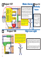
157 Water Alarm 73
Project # Description Page #
158 Continuity Tester 73
159 High Low Light
73
160 Flicker Clicker 74
161 Fast Flicker Clicker 74
162 Slow Flicker Clicker 74
163 Timer Tone 74
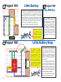
164 Little Battery 75
165 Tiny Battery 75
166 Little Battery Beep 75
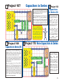
167 Capacitors in Series 76
168 Capacitors in Series (II) 76
169 Capacitors in Series (III) 76
170 More Capacitors in Series 76
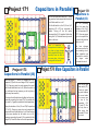
171 Capacitors in Parallel 77
172 Capacitors in Parallel (II) 77
173 Capacitors in Parallel (III) 77
174 More Capacitors in Parallel 77
175 Resistors in Series 78
176 Resistors in Parallel 78
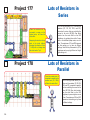
177 Lots of Resistors in Series 79
178 Lots of Resistors in Parallel 79
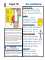
179 Be a Loud Musician 80
180 Be a Loud Musician (II) 80
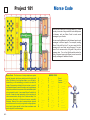
181 Morse Code 81
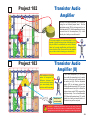
182 Transistor Audio Amplifier 82
183 Transistor Audio Amplifier (II) 82
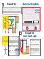
184 Make Your Own Parts 83
185 Color Touch Light 83
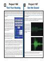
186 Test Your Hearing 84
187 See the Sound 84
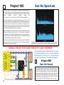
188 See the Spectrum 85
Project Listings
-19-
Page is loading ...
Page is loading ...
Page is loading ...
Page is loading ...
Page is loading ...
Page is loading ...
Page is loading ...
Page is loading ...
Page is loading ...
Page is loading ...
Page is loading ...
Page is loading ...
Page is loading ...
Page is loading ...
Page is loading ...
Page is loading ...
Page is loading ...
Page is loading ...
Page is loading ...
Page is loading ...
Page is loading ...
Page is loading ...
Page is loading ...
Page is loading ...
Page is loading ...
Page is loading ...
Page is loading ...
Page is loading ...
Page is loading ...
Page is loading ...
Page is loading ...
Page is loading ...
Page is loading ...
Page is loading ...
Page is loading ...
Page is loading ...
Page is loading ...
Page is loading ...
Page is loading ...
Page is loading ...
Page is loading ...
Page is loading ...
Page is loading ...
Page is loading ...
Page is loading ...
Page is loading ...
Page is loading ...
Page is loading ...
Page is loading ...
Page is loading ...
Page is loading ...
Page is loading ...
Page is loading ...
Page is loading ...
Page is loading ...
Page is loading ...
Page is loading ...
Page is loading ...
Page is loading ...
Page is loading ...
Page is loading ...
Page is loading ...
Page is loading ...
Page is loading ...
Page is loading ...
Page is loading ...
Page is loading ...
Page is loading ...
-
 1
1
-
 2
2
-
 3
3
-
 4
4
-
 5
5
-
 6
6
-
 7
7
-
 8
8
-
 9
9
-
 10
10
-
 11
11
-
 12
12
-
 13
13
-
 14
14
-
 15
15
-
 16
16
-
 17
17
-
 18
18
-
 19
19
-
 20
20
-
 21
21
-
 22
22
-
 23
23
-
 24
24
-
 25
25
-
 26
26
-
 27
27
-
 28
28
-
 29
29
-
 30
30
-
 31
31
-
 32
32
-
 33
33
-
 34
34
-
 35
35
-
 36
36
-
 37
37
-
 38
38
-
 39
39
-
 40
40
-
 41
41
-
 42
42
-
 43
43
-
 44
44
-
 45
45
-
 46
46
-
 47
47
-
 48
48
-
 49
49
-
 50
50
-
 51
51
-
 52
52
-
 53
53
-
 54
54
-
 55
55
-
 56
56
-
 57
57
-
 58
58
-
 59
59
-
 60
60
-
 61
61
-
 62
62
-
 63
63
-
 64
64
-
 65
65
-
 66
66
-
 67
67
-
 68
68
-
 69
69
-
 70
70
-
 71
71
-
 72
72
-
 73
73
-
 74
74
-
 75
75
-
 76
76
-
 77
77
-
 78
78
-
 79
79
-
 80
80
-
 81
81
-
 82
82
-
 83
83
-
 84
84
-
 85
85
-
 86
86
-
 87
87
-
 88
88


Ask a question and I''ll find the answer in the document
Finding information in a document is now easier with AI
Related papers
-
Snap Circuits SC750 ST Owner's manual
-
Snap Circuits SC100R Owner's manual
-
Snap Circuits rc snap rover User guide
-
-
-
-
-
-
Radio Shack SCP02 Owner's manual
-
Other documents
-
Misfit SHINE Operating instructions
-
Elenco CM200 Owner's manual
-
-
Elenco CM125 Owner's manual
-
-
-
 Widara Distant Voices Theremin Owner's manual
-
Aim to Wash! 90-7772 User guide
-
-
