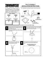
Automatic Discharge Pump Controller and Level Indicator

Dometic Automatic Discharge Pump Controller and Level Indicator, TankManager Installation guide

  • Hello! I am an AI chatbot trained to assist you with the Dometic Automatic Discharge Pump Controller and Level Indicator Installation guide. I’ve already reviewed the document and can help you find the information you need or explain it in simple terms. Just ask your questions, and providing more details will help me assist you more effectively!
  • What is the power consumption of the device?
    What is the maximum relay rating for the discharge pump?
    What is the material of the control panel face plate?
    What is the float switch rating?
    What are the available models of the control module?
1
TankManager
TM
AUTOMATIC DISCHARGE PUMP CONTROLLER
AND LEVEL INDICATOR
OWNER’S MANUAL
2
WARNING: When using this device, always exercise basic safety precautions, including the following:
• Read all instructions before installation or use.
• Never connect this device to any electrical circuit with other than 12 or 24 volt Direct Current or exceed
the amperage draw specied.
• Never install the control panel or the control module in an atmosphere with potentially ammable or explo-
sive vapors.
• This product is not to be installed in shower facilities.
• Never install the control module below the water line.
• Provides four holding tank level indication lights for Empty, Low, Mid, and Full levels. One level light is always
on to conrm that electrical power is applied.
• Includes keyed selector switch and “Discharge Pump On” light. An optional “Check Seacock” light is available
to use in conjunction with a seacock interlock switch.
• Prevents accidental overboard discharge in restricted waters when control switch is turned to “Off” position.
• Simplies plumbing by eliminating wye valves, seacocks, and vented loops for multiple toilet installations.
• Will eliminate stagnating sewage trapped in interconnecting hoses by wye valve operation.
• For use with a T-series discharge pump, TankWatch
®
4 level indicator cap and optional seacock interlock
system.
• 12 and 24 VDC models available.
• Key Switch Conguration 1 – Automatic Start–Automatic Shut-off Mode and Manual Mode:
Two different modes, automatic or manual, for holding tank discharge pump control.
Automatically discharges sewage directly overboard in unrestricted waters while in the “Automatic” mode.
In the “Automatic” mode, the Mid level oat will activate the discharge pump. The pump will then run until
the Low level switch is deactivated.
The Full level oat will turn on the discharge pump if the Mid level oat fails.
The “Automatic” mode will automatically maintain holding tank level between the Low and Mid level.
The “Manual” mode provides direct discharge pump control regardless of the level of the holding tank.
• Key Switch Conguration 2 – Manual Start–Automatic Shut-off:
Provides a manual start and an automatic shut-off of the discharge pump.
Key switch must be turned to the momentary Start position to activate the discharge pump. If the key
switch is then left in the Auto Off position, the discharge pump will shut off automatically when the Low
oat is deactivated.
Holding the key switch in the start position will activate the pump regardless of the level of the holding
tank.
Some ne-tuning of the oat switch locations may be necessary to obtain proper operation of the unit.
NOTE: Keep in mind that once you enter a No Discharge Zone, the TankManager must be switched to the “Off”
position and the key removed to prevent illegally discharging your holding tank. The United States Coast Guard
will allow a key-operated switch as a means to secure the overboard discharge pump system instead of securing
it with a padlock or wire tie.
Safety Instructions .................................................. 2
Product Features .................................................... 2
System Operation Diagram .................................... 3
Models and Accessories ......................................... 4
Specications ......................................................... 5
Installation Instructions ..................................... 5 – 6
Wiring Diagrams .............................................. 7 – 8
Dimensional Specications .................................... 9
Warranty ............................................................... 10
Control Panel Mounting Template ........................ 11
TABLE OF CONTENTS
SAFETY INSTRUCTIONS
PRODUCT FEATURES
3
• Discharge
pump shuts off
automatically
when tank level
drops below
Low probe.
• Discharge
pump light off.
• Empty light on.
• Discharge pump
shuts off when key
switch is released
from Manual position.
• Discharge pump
light off.
• Empty light on.
• Discharge
pump shuts off
automatically
when tank level
drops below
Low probe.
• Discharge
pump light off.
• Empty light on.
• Mid light on.
Tank contents
reach Mid level
probe. Holding tank
discharge pump
starts automatically.
• Discharge pump
light on.
• Full light on.
• Holding tank
discharge pump will
run only when
holding switch in the
Manual position.
• Discharge pump
light on.
• Full light on.
• Holding tank
discharge pump
started by turning
switch to the
momentary Start
position.
• Discharge pump
light on.
Switch Configuration 1
Auto Start - Auto Shut-off Mode:
Automatically empties holding tank at
Mid level, which is adjustable at time of
installation. Full level float will turn on
pump if Mid level float fails.
• Tank contents at
Mid level.
Mid light on.
• Tank contents
between Low
and Mid level
probe.
• Low light on.
• Tank is empty.
• Empty light on.
• Tank is empty.
• Empty light on.
• Tank contents
at Mid
level.
• Mid light on.
• Tank is empty.
• Empty light on.
Switch Configuration 2
Manual Start - Auto Shut-off Mode:
Holding tank discharge pump starts only
when key switch is momentarily held in the
Start position. Pump will continue running if
key is returned to the Auto Off position.
TankManager Pump Controller / Level Indicator
Switch Configuration 1
Manual Mode:
Holding tank discharge pump run
s only
when key switch is held in the Manual
position.
SYSTEM OPERATION DIAGRAM
4
Part Number Description
385310918 TMG Control Module, Auto Start, Single Head, 12VDC
385310919 TMG Control Module, Auto Start, Single Head, 24VDC
385310920 TMG Control Module, Auto Start, Multi Head, 12VDC
385310921 TMG Control Module, Auto Start, Multi Head, 24VDC
385310922 TMG Control Module, Manual Start, Single Head, 12VDC
385310923 TMG Control Module, Manual Start, Single Head, 24VDC
385310924 TMG Control Module, Manual Start, Multi Head, 12VDC
385310925 TMG Control Module, Manual Start, Multi Head, 24VDC
385310926 TMG Control Panel, Auto Start
385310927 TMG Control Panel, Auto Start with Seacock Monitoring Indicator
385310928 TMG Control Panel, Manual Start
385310929 TMG Control Panel, Manual Start with Seacock Monitoring Indicator
385311036 Key Replacement Kit
360301200 T-Series Discharge Pump – 12 VDC
360302400 T-Series Discharge Pump – 24 VDC
600343605 Seacock Interlock Switch for Conbraco 1-1/2” Seacock Only
600343675 Seacock Interlock Switch for Groco 1-1/2” Seacock Only
385230272 Universal Flange (3-inch NPT) with gasket and stainless steel hardware
385318714 “Do Not Flush” Panel
313000355 Level Indicator Cap without Vent, 22-inch Probes
313000350 Level Indicator Cap with Vent, 22-inch Probes
313000346 Level Indicator Cap without Vent, 45-inch Probes
313000345 Level Indicator Cap with Vent, 45-inch Probes
TankManager Model Selection and Compatibility Guide
Control Panel
Control Module
TMG-CP-AS
TMG-CP-AS
TMG-CP-AS
TMG-CP-AS
Auto Start /With-
out Seacock Light
Auto Start / With
Seacock Light
Manual Start /
Without Seacock
Light
Manual Start /
With Seacock
Light
X
X
X
X
X
X
X
X
X
X
X
X
X
X
X
X
TMG-CM-AS-SH-12
TMG-CM-MS-SH-12
TMG-CM-MS-SH-24
TMG-CM-MS-MH-12
TMG-CM-MS-MH-24
TMG-CM-AS-MH-24
TMG-CM-AS-SH-24
TMG-CM-AS-MH-12
Control Module, Auto Start,
Single Head, 12VDC
Control Module, Auto Start,
Single Head, 24VDC
Control Module, Auto Start,
Multi Head, 12VDC
Control Module, Auto Start,
Multi Head, 24VDC
Control Module, Manual Start,
Single Head, 12VDC
Control Module, Manual Start,
Single Head, 24VDC
Control Module, Manual Start,
Mutli Head, 12VDC
Control Module, Manual Start,
Multi Head, 24VDC
MODELS AND ACCESSORIES
5
Product Name: TankManager Automatic Discharge Pump Controller and Level Indicator
Electrical: Output Current Capability
Maximum Relay Rating for 12 or 24 VDC Discharge Pump: 40 amps inrush, 30 amps
continuous.
Float Switch Rating: 20 watts with resistive load.
Current Consumption
“Standby” Current Draw:
12 Volts DC: 0.016 amps
24 Volts DC: 0.016 amps
“Pump On” Current Draw (not including pump):
12 Volts DC: 0.190 amps
24 Volts DC: 0.095 amps
Materials: Control Panel Face Plate – polystyrene with protective coating
Keylock Switch – stainless steel facing
Key – nickel-plated brass
Control Module EnclosureABS
CONTROL MODULE
1. Select a mounting location as close as possible to the peripheral equipment, such as the level indicator cap,
discharge pump, and vacuum generator. This will allow all connectors to be attached without running any ad-
ditional wiring harnesses.
2. Make sure the control module will not be in direct contact with water and oil.
3. Attach the control module to the selected mounting area with four screws (not supplied).
4. Route wiring according to the wiring diagram enclosed. If the mating connectors are not available, simply cut
off the existing connectors and use any approved connector.
CONTROL PANEL
1. Select a mounting location away from direct contact with water and oil.
2. Conrm clearances for the panel behind the mounting surface. You will need a minimum clearance of
3 inches.
3. Cut out the mounting holes for the control panel. (See template included in this manual for cut-out and hole
locations.)
4. Do not mount the control panel until all wiring is routed to the panel.
5. Route wiring following the wiring diagram enclosed. If the mating connectors are not available, simply cut off
the existing connectors and use any approved connector.
6. Mount the control panel with the four #4 x 3/8-inch long pan-head stainless steel screws provided.
Notes:
The lens colors for the control panel lights are as follows:
The keylock switch wiring colors are as follows. Wires connect to the terminals on the back of the switch:
Check Seacock
(Optional)
Discharge Pump
On
Empty
Low Mid
Full
Green Yellow Amber Red
Green
Yellow
Terminal 1
Terminal 2
Terminal 7
Terminal 8
Conguration 1
(Auto Start)
Conguration 2
(Manual Start)
Red
Red
Brown
Brown
Blue
N/A
Red
Blue
SPECIFICATIONS
INSTALLATION INSTRUCTIONS
6
OPTIONAL ADJUSTABLE LEVEL INDICATOR CAP
1. The adjustable level indicator cap is designed for a 3-inch FPT opening. Order the optional universal ange
(Dometic P/N 230272) if tank is made of rigid material and not a holding tank.
2. Loosen the compression nuts on the adjustable probes and install the cap into the tank. Slide the #1 probe
tubing down until the oat touches the bottom of the tank. Tighten #1 probe compression nut and mark the
tubing at the top of the nut with a pen or pencil. Do not cut the tubing at this mark. Loosen the compression
nut, slide the tubing up, and carefully cut the tubing 1 5/8-inch (41 mm) below the mark without damaging
the switch wires. (NOTE: Tubing should only be cut with a roller guide tubing cutter (used for brass or copper
tubing) to prevent damaging the oat switch wires.) Pull the wires through the black wire cover and push the
tubing down into the compression nut until the black wire cover touches the compression nut.
3. Remove the cap from the tank and adjust the #2 probe for 1/2 full level. Tighten the compression nut and cut
the tubing off 3/8-inch (10mm) above the compression nut without damaging the switch wires. Slip the black
wire cover on to the top of the tubing.
5. For the TankManager system to work properly, the Low oat (#1 probe) must be positioned with the recessed
shoulder, white band, or the letters “NO” at the bottom. The Mid and Full oats (#2 and #3 probes) must be
positioned with the recessed shoulder, white band, or the letters “NO” up (see Figure 1). If the oat must be
repositioned, remove the C-clip from the switch body, ip the oat 180 degrees, and replace the C-clip.
PROBE SWITCH ADJUSTMENT
1. It is important that the Low and Mid oats of the TankWatch 4 level indicator cap are adjusted for the
TankManager to operate properly.
2. The #1 probe must be positioned just slightly above the diptube opening or tank outlet. If this oat is posi-
tioned too low, the discharge pump will not shut off properly. This is because the sewage level in the tank will
never drop below the level of the tank outlet. If the Low oat is adjusted below this critical level, it will never
disengage and turn off the discharge pump.
3. The location of the #2 probe is entirely up to the installer. The higher the oat is positioned, the longer the
discharge pump cycle will be. We recommend locating the oat approximately 4 inches above the #1 probe.
If either a longer or shorter pump cycle time is preferred, adjust the #2 probe accordingly. However, the Empty,
Low and Mid readings may not be true after adjustment. For example, if the #2 (Mid) probe switch is raised
several inches in order to obtain a longer pump cycle time, the Mid light will actually signal that the tank is slightly
fuller.
OPTIONAL UNIVERSAL FLANGE
1. Find and mark the top center of the tank.
2. Cut a 4 1/16-inch (103 mm) diameter hole in the top center of the tank.
3. Slip the ange into the hole and mark the location of the ve mounting holes.
4. Drill the ve mounting holes with a ¼-inch (6 mm) drill bit.
5. Remove the ange, clean all oils, grease and dirt from the mounting surface and allow to dry.
6. Apply liberal amounts of silicone rubber adhesive to the mounting surface and the underside of the ange.
7. Insert the gasket into the ange and align with the ve mounting holes.
8. Secure the ange with the screws, nuts and washers provided.
9. Install the oat switch cap.
Figure 1
VENT LINE
N
O
WASTE TANK
(Black and gray water)
N
O
MID/FULL
FLOATS
PROBE #1
(Empty or Low level)
PROBE #2
(Mid level)
PROBE #3
(High or Full level)
EMPTY/LOW
FLOAT
“NO”,
recessed
shoulder, or
white band
up
“NO”,
recessed
shoulder, or
white band
down
7
Single Head System Wiring Diagram
WIRING DIAGRAMS
8
Multi-Head Wiring Diagram
9
DIMENSIONAL SPECIFICATIONS
10
Dometic warrants, to the original purchaser only, that this product, if used for personal, family or household purposes,
is free from defects in material and workmanship for a period of one year from the date of purchase.
If this Dometic product is placed in commercial or business use, it will be warranted, to the original purchaser only,
to be free of defects in material and workmanship for a period of ninety (90) days from the date of purchase.
Dometic reserves the right to replace or repair any part of this product that proves, upon inspection by Dometic, to
be defective in material or workmanship. All labor and transportation costs or charges incidental to warranty service
are to be borne by the purchaser-user.
EXCLUSIONS
IN NO EVENT SHALL DOMETIC BE LIABLE FOR INCIDENTAL OR CONSEQUENTIAL DAMAGES, FOR
DAMAGES RESULTING FROM IMPROPER INSTALLATION, OR FOR DAMAGES CAUSED BY NEGLECT, ABUSE,
ALTERATION OR USE OF UNAUTHORIZED COMPONENTS. ALL IMPLIED WARRANTIES, INCLUDING ANY
IMPLIED WARRANTY OF MERCHANTABILITY OR FITNESS FOR ANY PARTICULAR PURPOSE, ARE LIMITED
TO A PERIOD OF ONE YEAR FROM DATE OF PURCHASE.
IMPLIED WARRANTIES
No person is authorized to change, add to, or create any warranty or obligation other than that set forth herein.
Implied warranties, including those of merchantability and tness for a particular purpose, are limited to one (1) year
from the date of purchase for products used for personal, family or household purposes, and ninety (90) days from
the date of purchase for products placed in commercial or business use.
OTHER RIGHTS
Some states do not allow limitations on the duration of an implied warranty, and some states do not allow exclusions
or limitations regarding incidental or consequential damages; so, the above limitations may not apply to you. This
warranty gives you specic legal rights and you may have other rights which vary from state to state.
To obtain warranty service, rst contact your local dealer from whom you purchased this product.
MANUFACTURER’S ONE-YEAR LIMITED WARRANTY
Dometic Corporation, Sanitation Division
13128 State Rt. 226, P.O. Box 38
Big Prairie, OH 44611 USA
1-800-321-9886 • Fax: 330-496-3097
www.Dometic.com
REVISION A
Form No. 600344573 10/17
©2017 Dometic Corporation
11
CONTROL PANEL MOUNTING TEMPLATE
12
THIS PAGE IS INTENTIONALLY LEFT BLANK.
/