Page is loading ...

00-99-000904/0509
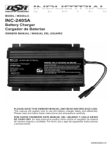
Model / Modelo / Modèle: INC-2405A
For 24-Volt Batteries / Para Baterías de 24-Voltios / Pour
Batteries de 24-V
READ THE ENTIRE MANUAL BEFORE USING THIS PRODUCT. •
FAILURE TO DO SO CAN RESULT IN SERIOUS INJURY OR DEATH.
LEA EL MANUAL COMPLETO ANTES DE UTILIZAR ESTE •
PRODUCTO. CUALQUIER FALLA PODRÍA RESULTAR EN SERIAS
LESIONES O PODRÍA SER MORTAL.
LIRE ENTIÈREMENT LE GUIDE AVANTD’UTILISER CE PRODUIT. •
L’ÉCHEC DE FAIRE AINSI PEUT S’ENSUIVRE DANS LA BLESSURE
SÉRIEUSE OU LA MORT.
OWNER’S MANUAL•
MANUAL DEL USUARIO•
GUIDE D’UTILISATION•
Voltage / Tensión / Tension: 24
Amperage / Amperaje / Ampérage: 5

TABLE OF CONTENTS / ÍNDICE / TABLE DES MATIÈRES
SECTION / SECCIÓN / PARTIE PAGE / PÀGINA
IMPORTANT SAFETY INSTRUCTIONS 1
PERSONAL PRECAUTIONS 2
PREPARING TO CHARGE 3
CHARGER LOCATION 3
DC CONNECTION PRECAUTIONS 3
FOLLOW THESE STEPS WHEN BATTERY IS
INSTALLED IN VEHICLE. 4
FOLLOW THESE STEPS WHEN BATTERY IS
OUTSIDE VEHICLE 4
BATTERY CHARGING - AC CONNECTIONS 5
ASSEMBLY INSTRUCTIONS 5
PRODUCT FEATURES 6
MOUNTING CHARGER TO A FLAT SURFACE 6
CONTROL PANEL 6
OPERATING INSTRUCTIONS 7
CALCULATING CHARGE TIME 7
MAINTENANCE INSTRUCTIONS 8
STORAGE INSTRUCTIONS 9
TROUBLESHOOTING 9
BEFORE RETURNING FOR REPAIR 9
TECHNICAL SPECIFICATIONS 10
REPLACEMENT PARTS 11
LIMITED WARRANTY 11
INSTRUCCIONES DE SEGURIDAD IMPORTANTES 13
PRECAUCIONES PERSONALES 14
PREPARACIÓN DE LA CARGA 15

UBICACIÓN DEL CARGADOR 15
PRECAUCIONES DE LA CONEXIÓN CC 16
SIGA ESTOS PASOS AL INSTALAR UNA BATERÍA EN
EL VEHÍCULO. 16
SIGA ESTOS PASOS CUANDO LA BATERÍA ESTÉ
AFUERA DEL VEHÍCULO. 17
BATERIA CARGANDO - CONEXIONES AC 17
INSTRUCCIONES DE ENSAMBLAJE 18
CARACTERÍSTICAS DEL PRODUCTO 18
MONTAJE DEL CARGADOR SOBRE UNA SUPERFICIE PLANA 19
PANEL DE CONTROL 19
INSTRUCCIONES DE OPERACIÓN 19
CÁLCULO DE TIEMPO DE CARGA 20
INSTRUCCIONES DE MANTENIMIENTO 21
INSTRUCCIONES DE ALMACENAJE 21
SOLUCIÓN DE PROBLEMAS 22
ANTES DE DEVOLVER EL CARGADOR PARA REPARACIÓN 22
ESPECIFICACIONES TÉCNICAS 23
INSTRUCCIONES PARA ENSAMBLE 23
GARANTÍA LIMITADA 24
CONSIGNES DE SÉCURITÉ IMPORTANTES 26
PRÉCAUTIONS PERSONNELLES 27
PRÉPARATION POUR LE CHARGEMENT 28
EMPLACEMENT DU CHARGEUR 28
PRÉCAUTIONS SUR LA CONNEXION C.C. 29
ÉTAPES À SUIVRE QUAND LA BATTERIE EST
INSTALLÉE DANS UN VÉHICULE. 29
ÉTAPES À SUIVRE QUAND LA BATTERIE EST
INSTALLÉE HORS DU VÉHICULE. 30

CHARGEMENT D’UNE BATTERIE – RACCORDEMENTS C.A. 30
DIRECTIVES DE MONTAGE 31
CARACTÉRISTIQUES 32
INSTALLER LE CHARGEUR SUR UNE SURFACE PLANE 32
PANNEAU DE CONTRÔLE 32
CONSIGNES D’UTILISATION 33
CALCUL DU TEMPS DE CHARGEMENT 34
CONSIGNES D’ENTRETIEN 35
DIRECTIVES D’ENTREPOSAGE 35
TABLEAU DE DÉPANNAGE 35
AVANT DE L’ENVOYER POUR RÉPARATION 36
SPÉCIFICATIONS TECHNIQUES 36
PIÈCES DE REMPLACEMENT 37
GARANTIE LIMITÉE 37

• 1 •
IMPORTANT: READ AND SAVE THIS SAFETY AND INSTRUCTION MANUAL.
IMPORTANT SAFETY INSTRUCTIONS1.
WARNING: This battery charger is to be used for charging 24 volt bat-
teries only. Use of this charger on other batteries could lead to severe
property damage or personal injury.
SAVE THESE INSTRUCTIONS – The INC-2405A offers a wide range of 1.1
features to accommodate your needs. This manual will show you how to
use your charger safely and effectively. Please read, understand and fol-
low these instructions and precautions carefully, as this manual contains
important safety and operating instructions.
WARNING: Pursuant to California Proposition 65, this product contains 1.2
chemicals known to the State of California to cause cancer and birth de-
fects or other reproductive harm.
Do not expose the charger to rain or snow.1.3
Use only recommended attachments. Use of an attachment not recom-1.4
mended or sold by Schumacher® Electric Corporation may result in a risk
of re, electric shock or injury to persons or damage to property.
To reduce the risk of damage to the electric plug or cord, pull by the plug 1.5
rather than the cord when disconnecting the charger.
An extension cord should not be used unless absolutely necessary. Use of 1.6
an improper extension cord could result in a risk of re and electric shock.
If an extension cord must be used, make sure:
That the pins on the plug of the extension cord are the same number, •
size and shape as those of the plug on the charger.
That the extension cord is properly wired and in good electrical •
condition.
That the wire size is large enough for the AC ampere rating of the char-•
ger as specied in the table in Section 8.2.
Do not operate the charger with a damaged cord or plug; take it to a quali-1.7
ed service person. (Call customer service at: 1-800-621-5485.)
Do not operate the charger if it has received a sharp blow, been dropped 1.8
or otherwise damaged in any way; take it to a qualied service person.
(Call customer service at: 1-800-621-5485.)
Do not disassemble the charger; take it to a qualied service person when 1.9
service or repair is required. Incorrect reassembly may result in a risk of
re or electric shock. (Call customer service at: 1-800-621-5485.)
To reduce the risk of electric shock, unplug the charger from the outlet 1.10
before attempting any maintenance or cleaning. Simply turning off the
controls will not reduce this risk.

• 2 •
WARNING – RISK OF EXPLOSIVE GASES.
WORKING IN THE VICINITY OF A LEAD-ACID BATTERY IS DANGER-
OUS. BATTERIES GENERATE EXPLOSIVE GASES DURING NOR-
MAL BATTERY OPERATION. FOR THIS REASON, IT IS OF UTMOST
IMPORTANCE THAT YOU FOLLOW THE INSTRUCTIONS EACH TIME
YOU USE THE CHARGER.
TO REDUCE THE RISK OF BATTERY EXPLOSION, FOLLOW THESE
INSTRUCTIONS AND THOSE PUBLISHED BY THE BATTERY MANU-
FACTURER AND THE MANUFACTURER OF ANY EQUIPMENT YOU
INTEND TO USE IN THE VICINITY OF THE BATTERY. REVIEW THE
CAUTIONARY MARKINGS ON THESE PRODUCTS AND ON THE
ENGINE.
PERSONAL PRECAUTIONS2.
Consider having someone close enough by to come to your aid when you 2.1
work near a lead-acid battery.
Have plenty of fresh water and soap nearby in case battery acid contacts 2.2
your skin, clothing or eyes.
Wear complete eye and body protection, including safety goggles and pro-2.3
tective clothing. Avoid touching your eyes while working near the battery.
If battery acid contacts your skin or clothing, wash immediately with soap 2.4
and water. If acid enters your eye, immediately ood the eye with cold run-
ning water for at least 10 minutes and get medical attention right away.
NEVER smoke or allow a spark or ame in the vicinity of a battery or 2.5
engine.
Be extra cautious to reduce the risk of dropping a metal tool onto the bat-2.6
tery. It might spark or short-circuit the battery or other electrical part that
may cause an explosion.
Remove personal metal items such as rings, bracelets, necklaces and 2.7
watches when working with a lead-acid battery. A lead-acid battery can
produce a short-circuit current high enough to weld a ring or the like to
metal, causing a severe burn.
Use this charger for charging a LEAD-ACID battery only. It is not intended 2.8
to supply power to a low voltage electrical system. Do not use this battery
charger for charging dry-cell batteries that are commonly used with home
appliances. These batteries may burst and cause injury to persons and
damage to property.
NEVER charge a frozen battery.2.9
NEVER overcharge a battery.2.10

• 3 •
PREPARING TO CHARGE3.
If it is necessary to remove the battery from the vehicle to charge it, al-3.1
ways remove the grounded terminal rst. Make sure all of the accessories
in the vehicle are off, to prevent arcing.
Be sure the area around the battery is well ventilated while the battery is 3.2
being charged.
Clean the battery terminals before charging the battery. During cleaning, 3.3
keep airborne corrosion from coming into contact with your eyes, nose
and mouth. Use baking soda and water to neutralize battery acid and help
eliminate airborne corrosion. Do not touch your eyes, nose or mouth.
Add distilled water to each cell until the battery acid reaches the level 3.4
specied by the battery manufacturer. Do not overll. For a battery without
removable cell caps, such as valve regulated lead-acid-batteries, carefully
follow the manufacturer’s recharging instructions.
Read, understand and follow all instructions for the charger, battery, 3.5
vehicle and any equipment used near the battery and charger. Study all of
the battery manufacturer’s specic precautions while charging and recom-
mended rates of charge.
Determine the voltage of the battery by referring to the vehicle owner’s 3.6
manual and make sure that the output voltage selector switch is set to the
correct voltage. If the charger has an adjustable charge rate, charge the
battery in the lowest rate rst.
Make sure that the charger cable clips make tight connections.3.7
CHARGER LOCATION4.
Locate the charger as far away from the battery as the DC cables permit.4.1
Never place the charger directly above the battery being charged; gases 4.2
from the battery will corrode and damage the charger.
Do not set the battery on top of the charger.4.3
Never allow battery acid to drip onto the charger when reading the electro-4.4
lyte specic gravity or lling the battery.
Do not operate the charger in a closed-in area or restrict the ventilation in 4.5
any way.
DC CONNECTION PRECAUTIONS5.
Connect and disconnect the DC output clips only after turning the charger 5.1
off and removing the AC plug from the electrical outlet. Never allow the
clips to touch each other.
Attach the clips to the battery and chassis, as indicated in steps 6.5, 6.6 5.2
and 7.2 through 7.4.

• 4 •
FOLLOW THESE STEPS WHEN BATTERY IS INSTALLED IN 6.
VEHICLE.
A SPARK NEAR THE BATTERY MAY CAUSE A BATTERY EXPLO-
SION. TO REDUCE THE RISK OF A SPARK NEAR THE BATTERY:
Position the AC and DC cables to reduce the risk of damage by the hood, 6.1
door and moving or hot engine parts.
Stay clear of fan blades, belts, pulleys and other parts that can cause 6.2
injury.
Check the polarity of the battery posts. The POSITIVE (POS, P, +) battery 6.3
post usually has a larger diameter then the NEGATIVE (NEG, N, -) post.
Determine which post of the battery is grounded (connected) to the chas-6.4
sis. If the negative post is grounded to the chassis (as in most vehicles),
see step 6.5. If the positive post is grounded to the chassis, see step 6.6.
For a negative-grounded vehicle, connect the POSITIVE (RED) clip from 6.5
the battery charger to the POSITIVE (POS, P, +) ungrounded post of the
battery. Connect the NEGATIVE (BLACK) clip to the vehicle chassis or
engine block away from the battery. Do not connect the clip to the carbure-
tor, fuel lines or sheet-metal body parts. Connect to a heavy gauge metal
part of the frame or engine block.
For a positive-grounded vehicle, connect the NEGATIVE (BLACK) clip 6.6
from the battery charger to the NEGATIVE (NEG, N, -) ungrounded post
of the battery. Connect the POSITIVE (RED) clip to the vehicle chassis or
engine block away from the battery. Do not connect the clip to the carbure-
tor, fuel lines or sheet-metal body parts. Connect to a heavy gauge metal
part of the frame or engine block.
When disconnecting the charger, turn all switches to off, disconnect the 6.7
AC cord, remove the clip from the vehicle chassis and then remove the
clip from the battery terminal.
See CALCULATING CHARGE TIME for length of charge information.6.8
FOLLOW THESE STEPS WHEN BATTERY IS OUTSIDE VEHICLE 7.
A SPARK NEAR THE BATTERY MAY CAUSE A BATTERY EXPLO-
SION. TO REDUCE THE RISK OF A SPARK NEAR THE BATTERY:
Check the polarity of the battery posts. The POSITIVE (POS, P, +) battery 7.1
post usually has a larger diameter than the NEGATIVE (NEG, N, -) post.
Attach at least a 24-inch long 6-gauge (AWG) insulated battery cable to 7.2
the NEGATIVE (NEG, N, -) battery post.
Connect the POSITIVE (RED) charger clip to the POSITIVE (POS, P, +) 7.3
post of the battery.
Position yourself and the free end of the cable you previously attached to 7.4
the NEGATIVE (NEG, N, -) battery post as far away from the battery as
possible – then connect the NEGATIVE (BLACK) charger clip to the free
end of the cable.

• 5 •
Do not face the battery when making the nal connection.7.5
When disconnecting the charger, always do so in the reverse order of the 7.6
connecting procedure and break the rst connection while as far away
from the battery as practical.
A marine (boat) battery must be removed and charged on shore. To 7.7
charge it onboard requires equipment specially designed for marine use.
BATTERY CHARGING - AC CONNECTIONS8.
This battery charger is for use on nominal 100 - 240 8.1
volt circuits.
DANGER – Never alter AC cord or plug provided – if it
does not t the outlet, have proper outlet installed by a
qualied electrician. Improper connection can result in
a risk of an electric shock.
Recommended minimum AWG size for extension 8.2
cords for battery chargers:
25 50 100 150
(7.6) (15.2) (30.5) (45.6)
0 2 18 18 18 16
2 3 18 18 16 14
3 4 18 18 16 14
4 5 18 18 14 12
5 6 18 16 14 12
6 8 18 16 12 10
8 10 18 14 12 10
10 12 16 14 10 8
12 14 16 12 10 8
14 16 16 12 10 8
16 18 14 12 8 8
18 20 14 12 8 6
a
If the input rating of a charger is given in watts rather than in
amperes, the corresponding ampere rating is to be determined
by dividing the wattage rating by the voltage rating ± for
example:
1250 watts/125 volts = 10 amperes
Length of cord, feet (m)
AWG size of cord
AC input rating,
amperes
a
But less
than
At least
ASSEMBLY INSTRUCTIONS9.
No assembly required.

• 6 •
PRODUCT FEATURES 10.
Charger Status LEDs (located on side of unit)1.
Battery Clamp Output Cord2.
3 Pin XLR 3-12C Output Cord3.
3/8” Dia. Ring Terminal Output Cord4.
AC Cord5.
1
2
3
4
5
MOUNTING CHARGER TO A FLAT SURFACE 11.
Donotmountchargerinalocationwithrestrictedairow.Thearea
where the charger is to be fastened must be dry, well ventilated and
away from any combustible material and fumes.
Turn off and disconnect charger.11.1
Place the back of the charger with mounting bracket against a secure, at 11.2
surface.
Securely mount charger to a at surface with a minimum of one and a half 11.3
inches of clearance on each side.
CONTROL PANEL12.
POWER ON (red) LED12.1 – The red POWER ON LED lights up when the
charger is plugged in and receiving AC power.

• 7 •
CHARGING STATUS (yellow and green) LED 12.2 – The CHARGING STA-
TUS LED glows yellow when the charger is charging and green when the
battery is charged and in maintain mode.
LED Color/Flash Pattern Explanation
Red On AC Power Present
Yellow On Charging
Green On Charge Complete
OPERATING INSTRUCTIONS13.
WARNING: Failure to follow instructions may cause damage or an explo-
sion. Read the entire instruction manual before use.
Make sure that the charger is unplugged from the AC outlet.13.1
Connect one of the three optional output cables to the charger output con-13.2
nector.
Connect the other end of the output cable to the battery.13.3
Plug the charger into the AC outlet. The POWER ON (red) LED will glow 13.4
to show that AC power is present. Then the green and yellow LED will
blink once as a self-test to make sure that the LED is operating properly.
After three seconds, the CHARGING (yellow) LED will glow to show that 13.5
charging has begun. If none of the LEDs glow, or if the CHARGING (yel-
low) LED does not glow, refer to the troubleshooting section. Charge time
may vary from less than one hour to 12 hours.
When charging is complete, the CHARGED (green) LED will glow and the 13.6
charger will automatically go into maintain mode. If desired, the charger
can now be unplugged from the AC outlet.
NOTE: If the battery has not reached at least 18-volts after ve minutes of
charging or at least 24-volts after four hours of charging, the charger will
abort the charging process and turn the yellow LED off.
CALCULATING CHARGE TIME14.
To determine the time needed to fully charge your battery, you must
rst determine the battery’s charge level with a hydrometer or electronic
Percent-of-Charge Tester. The following table will help you convert hy-
drometer readings to percent of charge values.

• 8 •
SpecicGravity Percent of Charge Percent of Charge
Needed
1.265 100% 0%
1.225 75% 25%
1.155 25% 75%
1.120 0% 100%
When the percent of charge and the Amp Hour (AH) rating of your battery
is known, you can calculate the approximate time needed to bring your
battery to a full charge.
To convert Reserve Capacity to Amp Hours, divide Reserve Capacity by 2,
and add 16:
Example:
Amp Hour Rating = Reserve Capacity + 16
2
NOTE: The Reserve Capacity can be obtained from the battery specica-
tion sheet or the owner’s manual.
To calculate the time needed for a charge:
Find the percent of charge needed (a battery at 50 percent charge that 1.
will be charged to 100 percent needs another 50 percent (.5).
Multiply the Amp Hour Rating by the charge needed (.5) and divide by 2.
the charger setting (5 amps).
Multiply the results by 1.25, and you will have the total time needed, in 3.
hours, to bring the battery to a full charge.
Add an additional hour for a deep-cycle battery.4.
Example:
Amp Hour Rating x % of charge needed x 1.25 = hours of charge
Charger Setting
100 (AH Rating) x .50 (charge needed) x 1.25 = 12.5 hours
5 (Charger Setting)
100 x .50 x 1.25 = 12.5
5
A 100-Ampere Hour Battery must charge for 12 ½ hours when using the
above example.
MAINTENANCE INSTRUCTIONS15.
Before performing maintenance, unplug and disconnect the battery char-15.1
ger (see sections 6.7 and 7.6).
After use, unplug the charger and use a dry cloth to wipe all battery corro-15.2
sion and other dirt or oil from the terminals, cords, and the charger case.

• 9 •
Have any cracked or frayed cables replaced by an authorized service 15.3
person.
Servicing does not require opening the unit, as there are no user-service-15.4
able parts.
STORAGE INSTRUCTIONS16.
Store charger unplugged, in an upright position. Cord will still conduct 16.1
electricity until it is unplugged from the outlet.
Store inside, in a dry, cool place (unless you’re using an on-board Marine 16.2
Charger).
Do not store clips on handle, clipped together, on or around metal, or 16.3
clipped to cables.
TROUBLESHOOTING17.
LED GUIDE/PROBLEM POSSIBLE CAUSE SOLUTION
The charger is plugged in
but the POWER ON (red)
LED is not lit.
No power at the AC
receptacle.
Poor electrical connection.
The battery charger is not
functioning properly.
Check for open fuse or
circuit breaker supplying
AC outlet.
Check power cord and
extension cord for loose
tting plug.
Call customer service
(1-800-621-5485).
The battery is connected
and the POWER ON
(red) LED is on, but the
CHARGING (yellow) LED
is not lit and charger is not
charging.
Battery connectors are not
making a good connec-
tion.
The battery is bad.
The battery charger is not
functioning properly.
Check for poor connection
at battery. Make sure con-
necting points are clean.
Have the battery checked
by a qualied service
person.
Call customer service
(1-800-621-5485).
BEFORE RETURNING FOR REPAIR18.
Please do not return for repair before speaking to a customer service
representative (1-800-621-5485).
When a charging problem arises, make certain that the battery is capable 18.1
of accepting a normal charge. Use a good battery to double check all con-
nections, AC outlet for a full 120-volts, charger clamps for correct polarity,
and the quality of the connections from the cables to the output connector
and from the output connector to the battery system. The output connec-
tors must be clean.

• 10 •
When a battery is very cold, partially charged or sulfated, it will not draw 18.2
the full rated amperes from the charger. It is dangerous and damaging
to a battery to force higher amperage into it than it can effectively use in
recharging.
When an unknown operating problem arises, please read the complete 18.3
manual and call the customer service number for information. Doing so
will usually eliminate the need for return.
If the above solutions do not eliminate the problem or for
information about troubleshooting or replacement parts,
call toll-free from anywhere in the U.S.A.
1-800-621-5485
7:00 am to 5:00 pm Central Time Monday thru Friday
TECHNICAL SPECIFICATIONS19.
This charger is intended for use with lead-acid and gel-cell batteries only.
Electrical
Nominal Operating Voltage (VAC) 100 – 240
Input Voltage Range (VAC) 85 – 264
Input Current (A rsm max) 2.9 @ 85V 60Hz
Output Power (W) 120 nom. 130 max.
Output Current (A max) 5.0
Output Voltage (VDC nom./
range)
24 / 2 – 29.5
Mechanical
Case Black Anodized Aluminum
Dimensions (inches) 7 L x 5½ W x 2 H
Weight 1.80 lbs
Connections
AC Power Input C13 Male Socket
DC Power Output Adapters Option #1 – Battery Clamp Output Cord
Option #2 – 3-Pin XLR 3-12C Output Cord
Option #3 – 3/8” Dia. Ring Terminal Output
Cord

• 11 •
REPLACEMENT PARTS20.
Battery Clamp Output Cord 38-99-00211120.1
3-Pin XLR 3-12C Output Cord 38-99-00184020.2
3/8” Dia. Ring Terminal Output Cord 38-99-00211220.3
LIMITED WARRANTY21.
SCHUMACHER ELECTRIC CORPORATION, 801 BUSINESS CENTER
DRIVE, MOUNT PROSPECT, IL 60056-2179, MAKES THIS LIMITED
WARRANTY TO THE ORIGINAL RETAIL PURCHASER OF THIS PROD-
UCT. THIS LIMITED WARRANTY IS NOT TRANSFERABLE OR AS-
SIGNABLE.
Schumacher Electric Corporation (the “Manufacturer”) warrants this bat-
tery charger for 1 year from the date of purchase at retail against defective
material or workmanship that may occur under normal use and care.
If your unit is not free from defective material or workmanship, Manufactur-
ers obligation under this warranty is solely to repair or replace your prod-
uct, with a new or reconditioned unit, at the option of the Manufacturer. It
is the obligation of the purchaser to forward the unit, along with mailing
charges prepaid to the Manufacturer or its authorized representatives in
order for repair or replacement to occur.
Manufacturer does not provide any warranty for any accessories used with
this product that are not manufactured by Schumacher Electric Corpora-
tion and approved for use with this product. This Limited Warranty is void
if the product is misused, subjected to careless handling, repaired, or
modied by anyone other than Manufacturer or if this unit is resold through
an unauthorized retailer.

• 12 •
Manufacturer makes no other warranties, including, but not limited to,
express, implied or statutory warranties, including without limitation, any
implied warranty of merchantability or implied warranty of tness for a par-
ticular purpose. Further, Manufacturer shall not be liable for any incidental,
special or consequential damage claims incurred by purchasers, users or
others associated with this product, including, but not limited to, lost prof-
its, revenues, anticipated sales, business opportunities, goodwill, business
interruption and any other injury or damage. Any and all such warranties,
other than the limited warranty included herein, are hereby expressly
disclaimed and excluded. Some states do not allow the exclusion or limita-
tion of incidental or consequential damages or length of implied warranty,
so the above limitations or exclusions may not apply to you. This warranty
gives you specic legal rights and it is possible you may have other rights
which vary from this warranty.
THIS LIMITED WARRANTY IS THE ONLY EXPRESS LIMITED WAR-
RANTY AND THE MANUFACTURER NEITHER ASSUMES OR AUTHO-
RIZES ANYONE TO ASSUME OR MAKE ANY OTHER OBLIGATION
TOWARDS THE PRODUCT OTHER THAN THIS WARRANTY.
Schumacher Electric Corporation Customer Service
1-800-621-5485
Monday – Friday 7:00 a.m. to 5:00 p.m. CST

• 37 •
Connexions
Entrée de l’alimentation CA Prise mâle C13
Adaptateurs en sortie
d’alimentation CC
Option #1 – Cordon de sortie avec pinces de la
batterie
Option #2 – Cordon de sortie 3 broches XLR
3-12C
Option #3 - Cordon de sortie de terminal en an-
neau de 3/8” Dia.
PIÈCES DE REMPLACEMENT20.
Cordon de sortie avec pinces de la batterie 38-99-002111
Cordon de sortie 3 broches XLR 3-12C 38-99-001840
Cordon de sortie de terminal en anneau de 3/8” Dia. 38-99-002112
GARANTIE LIMITÉE21.
SCHUMACHER ELECTRIC CORPORATION, 801 BUSINESS CENTER
DRIVE, MOUNT PROSPECT, IL 60056-2179, DONNE CETTE GA-
RANTIE LIMITÉE À L’ACHETEUR D’ORIGINE DU PRODUIT. CETTE
GARANTIE LIMITÉE N’EST NI TRANSFÉRABLE NI CESSIBLE.
/