Page is loading ...

Page 2 F o r t e c h n i c a l q u e s t i o n s , p l e a s e c a l l 1 - 8 8 8 - 8 6 6 - 5 7 9 7 . Item 60637
T a b l e o f Co n t e n t s
Safety ......................................................... 2
Setup .......................................................... 6
Specifications ............................................. 6
Operation ................................................... 10
Maintenance .............................................. 12
Parts List and Diagram .............................. 14
Warranty .................................................... 16
W ARNING S Y M B O L S AND D EF INIT IO NS
This is the safety alert symbol. It is used to alert you to potential personal injury hazards.
Obey all safety messages that follow this symbol to avoid possible injury or death.
Indicates a hazardous situation which, if not avoided,
will result in death or serious injury.
Indicates a hazardous situation which, if not avoided,
could result in death or serious injury.
Indicates a hazardous situation which, if not avoided,
could result in minor or moderate injury.
Addresses practices not related to personal injury.
S AF ET Y O PERAT IO N M AINT ENANCES ET UP

Page 3F o r t e c h n i c a l q u e s t i o n s , p l e a s e c a l l 1 - 8 8 8 - 8 6 6 - 5 7 9 7 .Item 60637
IM PO RT ANT S AF ET Y INF O RM AT IO N
G e n e r a l S a f e t y W a r n i n g s
W ARNING Re a d a l l s a f e t y w a r n i n g s a n d i n s t r u c t i o n s .
Failure to follow the warnings and instructions may result in electric shock, fire and/or serious injury.
S a v e a l l w a r n i n g s a n d i n s t r u c t i o n s f o r f u t u r e r e f e r e n c e .
The warnings, precautions, and instructions discussed in this instruction manual cannot cover all possible
conditions and situations that may occur. It must be understood by the operator that common sense
and caution are factors which cannot be built into this product, but must be supplied by the operator.
1. W o r k a r e a s a f e t y
a. K e e p w o r k a r e a c l e a n a n d w e l l l i t .
Cluttered or dark areas invite accidents.
b. D o n o t o p e r a t e t h e Co m p r e s s o r i n e x p l o s i v e
a t m o s p h e r e s , s u c h a s i n t h e p r e s e n c e
o f f l a m m a b l e l i q u i d s , g a s e s o r d u s t .
Compressor motors produce sparks
which may ignite the dust or fumes.
c. K e e p c h i l d r e n a n d b y s t a n d e r s a w a y
f r o m a n o p e r a t i n g c o m p r e s s o r .
2. El e c t r i c a l s a f e t y
a. Co m p r e s s o r p l u g s m u s t m a t c h t h e o u t l e t .
Ne v e r m o d i f y t h e p l u g i n a n y w a y .
D o n o t u s e a n y a d a p t e r p l u g s w i t h g r o u n d e d
c o m p r e s s o r s . Standard plugs and matching
outlets will reduce risk of electric shock.
b. D o n o t e x p o s e c o m p r e s s o r t o r a i n o r w e t
c o n d i t i o n s . Water entering a compressor
will increase the risk of electric shock.
c. D o n o t a b u s e t h e c o r d . Ne v e r u s e t h e
c o r d f o r u n p l u g g i n g t h e c o m p r e s s o r .
K e e p c o r d a w a y f r o m h e a t , o i l , s h a r p e d g e s
o r m o v i n g p a r t s . Damaged or entangled
cords increase the risk of electric shock.
3. Pe r s o n a l s a f e t y
a. S t a y a l e r t , w a t c h w h a t y o u a r e d o i n g a n d
u s e c o m m o n s e n s e w h e n o p e r a t i n g t h i s
c o m p r e s s o r . D o n o t u s e t h i s c o m p r e s s o r
w h i l e y o u a r e t i r e d o r u n d e r t h e i n f l u e n c e
o f d r u g s , a l c o h o l o r m e d i c a t i o n . A moment
of inattention while operating a compressor
may result in serious personal injury.
b. Us e p e r s o n a l p r o t e c t i v e e q u i p m e n t .
Al w a y s w e a r ANS I- a p p r o v e d e y e
p r o t e c t i o n d u r i n g s e t u p a n d u s e .
c. Pr e v e n t u n i n t e n t i o n a l s t a r t i n g . En s u r e t h e
s w i t c h i s i n t h e o f f - p o s i t i o n b e f o r e c o n n e c t i n g
t o p o w e r s o u r c e o r m o v i n g t h e c o m p r e s s o r .
4. Co m p r e s s o r u s e a n d c a r e
a. D o n o t u s e t h e c o m p r e s s o r i f t h e s w i t c h
d o e s n o t t u r n i t o n a n d o f f . Any compressor
that cannot be controlled with the switch
is dangerous and must be repaired.
b. D i s c o n n e c t t h e p l u g f r o m t h e p o w e r s o u r c e
b e f o r e m a k i n g a n y a d j u s t m e n t s , c h a n g i n g
a c c e s s o r i e s , o r s t o r i n g t h e c o m p r e s s o r .
Such preventive safety measures reduce the
risk of starting the compressor accidentally.
c. S t o r e a n i d l e c o m p r e s s o r o u t o f t h e r e a c h
o f c h i l d r e n a n d d o n o t a l l o w p e r s o n s
u n f a m i l i a r w i t h t h e c o m p r e s s o r o r t h e s e
i n s t r u c t i o n s t o o p e r a t e i t . A compressor is
dangerous in the hands of untrained users.
d. M a i n t a i n t h e c o m p r e s s o r . K e e p t h e
c o m p r e s s o r c l e a n f o r b e t t e r a n d s a f e r
p e r f o r m a n c e . F o l l o w i n s t r u c t i o n s f o r
l u b r i c a t i n g a n d c h a n g i n g a c c e s s o r i e s .
K e e p d r y , c l e a n a n d f r e e f r o m o i l a n d g r e a s e .
Ch e c k f o r m i s a l i g n m e n t o r b i n d i n g o f m o v i n g
p a r t s , b r e a k a g e o f p a r t s a n d a n y o t h e r
c o n d i t i o n t h a t m a y a f f e c t t h e c o m p r e s s o r ’ s
o p e r a t i o n . If d a m a g e d , h a v e t h e c o m p r e s s o r
r e p a i r e d b e f o r e u s e . Many accidents are
caused by a poorly maintained compressor.
e. Us e t h e c o m p r e s s o r i n a c c o r d a n c e w i t h
t h e s e i n s t r u c t i o n s , t a k i n g i n t o a c c o u n t
t h e w o r k i n g c o n d i t i o n s a n d t h e w o r k t o
b e p e r f o r m e d . Use of the compressor for
operations different from those intended
could result in a hazardous situation.
5. S e r v i c e
a. H a v e y o u r c o m p r e s s o r s e r v i c e d b y a
q u a l i f i e d r e p a i r p e r s o n u s i n g o n l y i d e n t i c a l
r e p l a c e m e n t p a r t s . This will ensure that the
safety of the compressor is maintained.
S AF ET YO PERAT IO NM AINT ENANCE S ET UP

Page 4 F o r t e c h n i c a l q u e s t i o n s , p l e a s e c a l l 1 - 8 8 8 - 8 6 6 - 5 7 9 7 . Item 60637
Ai r Co m p r e s s o r S a f e t y W a r n i n g s
1. Ri s k o f f i r e o r e x p l o s i o n - d o n o t s p r a y f l a m m a b l e
l i q u i d i n a c o n f i n e d a r e a o r t o w a r d s a h o t s u r f a c e .
S p r a y a r e a m u s t b e w e l l - v e n t i l a t e d . D o n o t
s m o k e w h i l e s p r a y i n g o r s p r a y w h e r e s p a r k o r
f l a m e i s p r e s e n t . Ar c i n g p a r t s - k e e p c o m p r e s s o r
a t l e a s t 2 0 f e e t a w a y f r o m e x p l o s i v e v a p o r s ,
s u c h a s w h e n s p r a y i n g w i t h a s p r a y g u n .
2. Ri s k o f b u r s t i n g - d o n o t a d j u s t r e g u l a t o r h i g h e r
t h a n m a r k e d m a x i m u m p r e s s u r e o f a t t a c h m e n t .
3. Ri s k o f i n j u r y - d o n o t d i r e c t a i r
s t r e a m a t p e o p l e o r a n i m a l s .
4. D o n o t u s e t o s u p p l y b r e a t h i n g a i r .
5. D o n o t l e a v e c o m p r e s s o r u n a t t e n d e d
f o r a n e x t e n d e d p e r i o d w h i l e p l u g g e d i n .
Un p l u g c o m p r e s s o r a f t e r w o r k i n g .
6. K e e p c o m p r e s s o r w e l l - v e n t i l a t e d .
D o n o t c o v e r c o m p r e s s o r d u r i n g u s e .
7. Drain Tank daily and after use. Internal rust causes
tank failure and explosion.
8. Do not remove the valve cover or
adjust internal components.
9. Compressor head gets hot during operation.
Do not touch it or allow children nearby during
or immediately following operation.
10. Do not use the air hose to move the compressor.
11. Release the pressure in the
storage tank before moving.
12. The use of accessories or attachments not
recommended by the manufacturer may
result in a risk of injury to persons.
13. All air line components, including hoses, pipe,
connectors, filters, etc., must be rated for a minimum
working pressure of 150 PSI, or 150% of the
maximum system pressure, whichever is greater.
14. USE OF AN EXTENSION CORD IS NOT
RECOMMENDED. If you choose to use an
extension cord, use the following guidelines:
T AB L E A: RECO M M END ED M INIM UM W IRE
G AUG E F O R EX T ENS IO N CO RD S
( 1 2 0 V O L T )
NAM EPL AT E
AM PERES
( a t f u l l l o a d )
EX T ENS IO N CO RD
L ENG T H
25′ 50′ 100′ 150′
0 – 6 18 16 16 14
6.1 – 10 18 16 D o n o t u s e .
10.1 – 12 16 16 D o n o t u s e .
12.1 – 16 14 12 D o n o t u s e .
a. Make sure your extension cord
is in good condition.
b. Be sure to use an extension cord which is heavy
enough to carry the current your product will draw.
An undersized cord will cause a drop in line
voltage resulting in loss of power and overheating.
Table A shows the correct size to use depending
on cord length and nameplate ampere rating.
If in doubt, use the next heavier gauge. The
smaller the gauge number, the heavier the cord.
15. Industrial applications must follow OSHA guidelines.
16. Maintain labels and nameplates on the
compressor. These carry important safety
information. If unreadable or missing, contact
Harbor Freight Tools for a replacement.
17. This product is not a toy.
Keep it out of reach of children.
18. People with pacemakers should consult their
physician(s) before use. Electromagnetic fields in
close proximity to heart pacemaker could cause
pacemaker interference or pacemaker failure.
19. WARNING: The brass components of
this product contain lead, a chemical
known to the State of California to cause
birth defects (or other reproductive harm).
(California Health & Safety code § 25249.5, et seq.)
20. WARNING: Handling the cord on this product will
expose you to lead, a chemical known to the State
of California to cause cancer, and birth defects or
other reproductive harm. Wash hands after handling.
(California Health & Safety Code § 25249.5, et seq.)
S AV E T H ES E INS T RUCT IO NS .
S AF ET Y O PERAT IO N M AINT ENANCES ET UP

Page 5F o r t e c h n i c a l q u e s t i o n s , p l e a s e c a l l 1 - 8 8 8 - 8 6 6 - 5 7 9 7 .Item 60637
G r o u n d i n g
T O PREV ENT EL ECT RIC S H O CK AND D EAT H
F RO M INCO RRECT G RO UND ING W IRE CO NNECT IO N:
Ch e c k w i t h a q u a l i f i e d e l e c t r i c i a n i f y o u a r e i n d o u b t a s t o w h e t h e r t h e o u t l e t i s p r o p e r l y g r o u n d e d .
D o n o t m o d i f y t h e p o w e r c o r d p l u g p r o v i d e d w i t h t h e c o m p r e s s o r .
Ne v e r r e m o v e t h e g r o u n d i n g p r o n g f r o m t h e p l u g . D o n o t u s e t h e c o m p r e s s o r i f t h e p o w e r c o r d o r p l u g i s
d a m a g e d . If d a m a g e d , h a v e i t r e p a i r e d b y a s e r v i c e f a c i l i t y b e f o r e u s e . If t h e p l u g w i l l n o t f i t t h e o u t l e t , h a v e a
p r o p e r o u t l e t i n s t a l l e d b y a q u a l i f i e d e l e c t r i c i a n .
1 1 0 - 1 2 0 V AC G r o u n d e d Co m p r e s s o r s : Co m p r e s s o r s w i t h T h r e e Pr o n g Pl u g s
1. In the event of a malfunction or breakdown,
grounding provides a path of least resistance for
electric current to reduce the risk of electric shock.
This compressor is equipped with an electric
cord having an equipment-grounding conductor
and a grounding plug. The plug must be
plugged into a matching outlet that is properly
installed and grounded in accordance
with all local codes and ordinances.
2. Do not modify the plug provided –
if it will not fit the outlet, have the proper
outlet installed by a qualified electrician.
3. Improper connection of the equipment-grounding
conductor can result in a risk of electric shock.
The conductor with insulation having an outer
surface that is green with or without yellow
stripes is the equipment-grounding conductor.
If repair or replacement of the electric cord or
plug is necessary, do not connect the equipment-
grounding conductor to a live terminal.
4. Check with a qualified electrician or service
personnel if the grounding instructions are
not completely understood, or if in doubt as to
whether the compressor is properly grounded.
5. Use only 3-wire extension cords that have
3-prong grounding plugs and 3-pole receptacles
that accept the compressor’s plug.
6. Repair or replace damaged or worn cord immediately.
1 2 5 V AC 3 - Pr o n g Pl u g a n d O u t l e t
( f o r u p t o 1 2 5 V AC a n d u p t o 1 5 A)
G r o u n d i n g
Pi n
7. This compressor is intended for use on a
circuit that has an outlet that looks like the one
illustrated above in 1 2 5 V AC 3 - Pr o n g Pl u g
a n d O u t l e t . The compressor has a grounding
plug that looks like the plug illustrated above
in 1 2 5 V AC 3 - Pr o n g Pl u g a n d O u t l e t .
8. The outlet must be properly installed and grounded
in accordance with all codes and ordinances.
9. Do not use an adapter to connect this
compressor to a different outlet.
S y m b o l o g y
PS I
Pounds per square inch of pressure
CF M
Cubic Feet per Minute flow
S CF M
Cubic Feet per Minute flow
at standard conditions
NPT
National pipe thread, tapered
NPS
National pipe thread, straight
Double Insulated
Canadian Standards Association
Underwriters Laboratories, Inc.
V AC
Volts Alternating Current
A
Amperes
S AF ET YO PERAT IO NM AINT ENANCE S ET UP

Page 6 F o r t e c h n i c a l q u e s t i o n s , p l e a s e c a l l 1 - 8 8 8 - 8 6 6 - 5 7 9 7 . Item 60637
S p e c i f i c a t i o n s
Electrical Rating 120VAC / 60Hz / 2.6 A
Air Outlet Size
1
/
4
″ -18 NPT
Air Pressure
Shut-off 100 PSI
Restart 85 PSI
Air Tank Capacity 3 Gallons
Air Flow Capacity
0.6 SCFM @ 90 PSI
1 SCFM @ 40 PSI
Fuse Size 3A ( r e p l a c e o n l y w i t h s a m e s i ze a n d t y p e )
2 2 7 8 4 7
In s t r u c t i o n s f o r p u t t i n g i n t o u s e
Re a d t h e ENT IRE IM PO RT ANT S AF ET Y INF O RM AT IO N s e c t i o n a t t h e b e g i n n i n g o f t h i s
m a n u a l i n c l u d i n g a l l t e x t u n d e r s u b h e a d i n g s t h e r e i n b e f o r e s e t u p o r u s e o f t h i s p r o d u c t .
T O PREV ENT S ERIO US INJ URY F RO M ACCID ENT AL O PERAT IO N:
T u r n t h e Po w e r S w i t c h “O F F ” a n d u n p l u g t h e Ai r Co m p r e s s o r f r o m i t s e l e c t r i c a l
o u t l e t b e f o r e a s s e m b l i n g o r m a k i n g a n y a d j u s t m e n t s t o t h e c o m p r e s s o r .
No t e : For additional information regarding the parts listed in the following pages,
refer to the Assembly Diagram near the end of this manual.
F u n c t i o n s
F u s e
H o l d e r
O u t p u t Ai r
Pr e s s u r e
G a u g e
S w i t c h
T a n k Ai r
Pr e s s u r e
G a u g e
S a f e t y
V a l v e
Re g u l a t o r
K n o b
Ai r
O u t l e t
S AF ET Y O PERAT IO N M AINT ENANCES ET UP

Page 7F o r t e c h n i c a l q u e s t i o n s , p l e a s e c a l l 1 - 8 8 8 - 8 6 6 - 5 7 9 7 .Item 60637
As s e m b l y / M o u n t i n g
1. Break in the new Air Compressor as follows:
a. Turn the Power Switch off and unplug the unit.
Insert a male coupler (sold separately)
into the female Quick Coupler and fully
open all regulators and valves.
b. Plug in the Power Cord.
c. Turn the Power Switch ON.
d. Let the unit run for 30 minutes.
Air will expel freely through the Coupler.
e. Turn the Power Switch OFF.
f. Unplug the Power Cord and
remove the male coupler.
2. Connect a regulator valve, an inline shut off valve
and a 1/4″ NPT air hose to the Quick Coupler
(all sold separately). The air hose must be long
enough to reach the work area with enough extra
length to allow free movement while working.
No t e : An i n - l i n e s h u t o f f b a l l v a l v e i s a n i m p o r t a n t
s a f e t y d e v i c e b e c a u s e i t c o n t r o l s t h e a i r s u p p l y e v e n
i f t h e a i r h o s e i s r u p t u r e d . T h e s h u t o f f v a l v e s h o u l d
b e a b a l l v a l v e b e c a u s e i t c a n b e c l o s e d q u i c k l y .
3. Depending on the tool which you will be
using with this compressor, you may need to
incorporate additional components, such as an
in-line oiler, a filter, or a dryer (all sold separately),
as shown on Figure A on page 8 and
Figure B on page 9. Consult your air
tool’s manual for needed accessories.
S AF ET YO PERAT IO NM AINT ENANCE S ET UP

Page 8 F o r t e c h n i c a l q u e s t i o n s , p l e a s e c a l l 1 - 8 8 8 - 8 6 6 - 5 7 9 7 . Item 60637
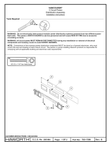
F i g u r e A: Po r t a b l e Ai r S u p p l y S e t u p
G
A
E
E H
F
B
Non-lubricated
Tools
Lubricated
Tools
A
B
C
C
D
A
D e s c r i p t i o n F u n c t i o n
A Air Hose Connects air to tool
B Filter Prevents dirt and condensation from damaging tool or workpiece
C Regulator Adjusts air pressure to tool
D Lubricator (optional) For air tool lubrication
E Coupler and Plug Provides quick connection and release
F Leader Hose (optional) Increases coupler life
G Air Cleaner / Dryer (optional) Prevents water vapor from damaging workpiece
H Air Adjusting Valve (optional) For fine tuning airflow at tool
S AF ET Y O PERAT IO N M AINT ENANCES ET UP

Page 9F o r t e c h n i c a l q u e s t i o n s , p l e a s e c a l l 1 - 8 8 8 - 8 6 6 - 5 7 9 7 .Item 60637
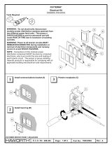
F i g u r e B : S t a t i o n a r y Ai r S u p p l y S e t u p
N
L
L O
M
C
C
Non-lubricated
Tools
Lubricated
Tools
H
I
I
J
J
K
H
F
G
E
S lop e
F
F
B B
A
A
C
D
D e s c r i p t i o n F u n c t i o n
A Vibration Pads For noise and vibration reduction
B Anchor Bolts Secures air compressor in place
C Ball Valve Isolates sections of system for maintenance
D Isolation Hose For vibration reduction
E Main Air Line - 3/4″ minimum recommended Distributes air to branch lines
F Ball Valve To drain moisture from system
G Branch Air Line -1/2″ minimum recommended Brings air to point of use
H Air Hose Connects air to tool
I Filter Prevents dirt and condensation from damaging tool or workpiece
J Regulator Adjusts air pressure to tool
K Lubricator (optional) For air tool lubrication
L Coupler and Plug Provides quick connection and release
M Leader Hose (optional) Increases coupler life
N Air Cleaner / Dryer (optional) Prevents water vapor from damaging workpiece
O Air Adjusting Valve (optional) For fine tuning airflow at tool
S AF ET YO PERAT IO NM AINT ENANCE S ET UP

Page 10 F o r t e c h n i c a l q u e s t i o n s , p l e a s e c a l l 1 - 8 8 8 - 8 6 6 - 5 7 9 7 . Item 60637
O p e r a t i n g In s t r u c t i o n s
Re a d t h e ENT IRE IM PO RT ANT S AF ET Y INF O RM AT IO N s e c t i o n a t t h e b e g i n n i n g o f t h i s
m a n u a l i n c l u d i n g a l l t e x t u n d e r s u b h e a d i n g s t h e r e i n b e f o r e s e t u p o r u s e o f t h i s p r o d u c t .
Co m p r e s s o r Ar e a S e t Up
1. Designate a work area that is clean and well-lit.
The work area must not allow access by
children or pets to prevent injury.
2. Locate the Compressor on a flat level surface to
ensure proper pump lubrication and to prevent
damage to the unit. Keep at least 12″ of space
around the unit to allow air circulation.
3. Route the power cord from the compressor
to the grounded wall outlet, along a safe path
without creating a tripping hazard or exposing
the power cord to possible damage.
G e n e r a l O p e r a t i o n
1. Turn red regulator knob counterclockwise completely.
2. Close the Drain Valve.
3. Plug the Air Compressor Power Cord into
a grounded 120 VAC electrical outlet.
4. Turn the Switch ON.
5. Allow the Air Compressor to build
up pressure until it cycles off.
No t e : At the beginning of the day’s first use of the
Air Compressor, check for air leaks by applying soapy
water to connections while the Air Compressor is
pumping and after pressure cut-out. Look for air bubbles.
If air bubbles are present at connections, tighten
connections. Do not use the Air Compressor
unless all connections are air tight, the extra air
leaking out will cause the compressor to operate
too often, increasing wear on the compressor.
No t e : As long as the Power Switch is ON, the operation
of the Air Compressor is automatic, controlled by an
internal pressure switch. The Compressor will turn on
automatically when the air pressure drops to 85 PSI,
and will turn off automatically when the
air pressure reaches 100 PSI.
W ARNING ! T O PREV ENT S ERIO US
INJ URY AND D EAT H F RO M EX PL O S IO N:
D o n o t a d j u s t t h e i n t e r n a l
p r e s s u r e s w i t c h . Any change to the
automatic pressure levels may cause
excess pressure to accumulate,
causing a hazardous situation.
6.
AF T ER the Compressor builds up enough
pressure and shuts off, adjust the Air Compressor’s
Regulator Knob so that the air output is enough
to properly power the tool, but the output will
not exceed the tool’s maximum air pressure at
any time. Turn the knob clockwise to increase
the pressure and counter-clockwise to decrease
pressure. Adjust the pressure gradually, while
checking the air output gauge to set the pressure.
S AF ET Y O PERAT IO N M AINT ENANCES ET UP

Page 11F o r t e c h n i c a l q u e s t i o n s , p l e a s e c a l l 1 - 8 8 8 - 8 6 6 - 5 7 9 7 .Item 60637
7. Make sure the air tool’s throttle or switch is in the
off position. Connect the air tool to the air hose.
8. Open the in-line Shutoff Valve.
No t e : Allow adequate time when filling tires.
The larger the tire, the more time to fill is needed.
No t e : This product is designed for inflation,
stapling, brad nailing and air brushing.
9. Use the air tool as needed.
10. After the job is complete, turn the Power Switch OFF.
11. Unplug the Air Compressor.
12. Close the in-line Shutoff Valve.
13. Bleed air from the tool then disconnect the tool.
14. Turn the Drain Valve, at the bottom of the Tank,
two turns to release any built-up moisture and the
internal tank pressure. Close the valve after moisture
has drained out. Do not remove the Drain Valve.
15. Clean, then store the Air Compressor indoors.
Em e r g e n c y D e p r e s s u r i za t i o n
If it is necessary to quickly depressurize the Compressor, turn the Power Switch OFF.
Then, pull on the ring on the Safety Valve to quickly release stored air pressure.
Au t o m a t i c S h u t o f f S y s t e m
1. If the Compressor automatically shuts off
before reaching its normal cutoff pressure:
a. Shut off all tools.
b. Wait until the Compressor cools down
(about 10 minutes);
c. If the unit does not start up again on its own,
check the Fuse next to the switch
and replace as needed;
d. Resume operation.
2. Possible causes of repeated automatic
shut off of the compressor are:
a. Using an extension cord that is too long or narrow;
b. An air leak or open hose causing the compressor
to cycle too often and build up heat.
3. Correct any issues before further use to
avoid damage to the compressor.
S AF ET YO PERAT IO NM AINT ENANCE S ET UP

Page 12 F o r t e c h n i c a l q u e s t i o n s , p l e a s e c a l l 1 - 8 8 8 - 8 6 6 - 5 7 9 7 . Item 60637
M a i n t e n a n c e a n d S e r v i c i n g
Pr o c e d u r e s n o t s p e c i f i c a l l y e x p l a i n e d i n t h i s m a n u a l m u s t
b e p e r f o r m e d o n l y b y a q u a l i f i e d t e c h n i c i a n .
T O PREV ENT S ERIO US INJ URY F RO M ACCID ENT AL O PERAT IO N:
T u r n t h e Po w e r S w i t c h “O F F ” a n d u n p l u g t h e Co m p r e s s o r f r o m i t s e l e c t r i c a l o u t l e t
b e f o r e p e r f o r m i n g a n y i n s p e c t i o n , m a i n t e n a n c e , o r c l e a n i n g p r o c e d u r e s .
T O PREV ENT S ERIO US INJ URY F RO M CO M PRES S O R F AIL URE:
D o n o t u s e d a m a g e d e q u i p m e n t . If a b n o r m a l n o i s e o r v i b r a t i o n o c c u r s ,
h a v e t h e p r o b l e m c o r r e c t e d b e f o r e f u r t h e r u s e .
Cl e a n i n g , M a i n t e n a n c e , a n d L u b r i c a t i o n
1. B EF O RE EACH US E, inspect the general
condition of the air compressor. Check for:
• loose hardware,
• misalignment or binding of moving parts,
• damaged belts,
• cracked or broken parts,
• damaged electrical wiring, and
• any other condition that may
affect its safe operation.
2. AF T ER US E, wipe external surfaces of
the compressor with a clean cloth.
3.
W ARNING ! If t h e s u p p l y c o r d o f t h i s
c o m p r e s s o r i s d a m a g e d , i t m u s t b e r e p l a c e d
o n l y b y a q u a l i f i e d s e r v i c e t e c h n i c i a n .
M a i n t e n a n c e S c h e d u l e
Following are general guidelines for maintenance checks of the Air Compressor.
No t e : The environment in which the compressor is used, and the frequency of use can affect how often
you will need to check the Air Compressor components and perform maintenance procedures.
D a i l y :
a. Make sure all nuts and bolts are tight.
b. Drain moisture from air tank.
c. Check for abnormal noise or vibration.
d. Check for air leaks.
*
e. Wipe off any oil or dirt from the compressor.
**
* To check for air leaks, apply soapy water to joints while
the Air Compressor is pressurized. Look for air bubbles.
** To clean the compressor surface, wipe with
a damp cloth, using a mild detergent or mild solvent.
M o n t h l y :
a. Inspect Safety Valve.
D r a i n i n g M o i s t u r e f r o m t h e T a n k
The Drain Valve is located under the Tank. It must be used daily to release all trapped air and
moisture from the Tank. This will eliminate condensation which can cause tank corrosion.
CAUT IO N! Do not open the Drain Valve so that more than four threads are showing.
1. Turn the Power switch of the compressor off.
2. Place a collection pan under the Drain Valve.
3. Unthread the Drain Valve two or three turns ONLY.
4. When all the pressure and moisture is released,
close the Drain Valve.
S AF ET Y O PERAT IO N M AINT ENANCES ET UP

Page 13F o r t e c h n i c a l q u e s t i o n s , p l e a s e c a l l 1 - 8 8 8 - 8 6 6 - 5 7 9 7 .Item 60637
T r o u b l e s h o o t i n g
Pr o b l e m Po s s i b l e Ca u s e s L i k e l y S o l u t i o n s
Compressor does
not start or restart
1. Tank(s) already pressurized.
2. Power cord not plugged in properly.
3. No power at outlet.
4. Fuse blown.
5. Building power supply circuit tripped
or blown fuse.
6. Cord wire size is too small or
cord is too long to properly
power compressor.
7. Compressor needs service.
1. No problem. Compressor will start when needed.
2. Check that cord is plugged in securely.
3. Reset circuit breaker, or have outlet
serviced by a qualified technician.
4. Check and replace Fuse as needed.
5. Reset circuit or replace fuse. Check for low voltage
conditions. It may be necessary to disconnect
other electrical appliances from the circuit or
move the compressor to its own circuit.
6. Use larger diameter or shorter extension cord or
eliminate extension cord. See Recommended Wire
Gauge for Extension Cords in Safety section.
7. Have unit inspected by a qualified technician.
Compressor not
building enough
air pressure
1. Air filters need cleaning/replacing.
2. Check Valve needs service.
3. Compressor not large enough for
job.
4. Loose fittings.
5. Hose or hose connections
too narrow.
6. High altitude reducing air output.
1. Check inlet and outlet filters.
Clean and/or replace as needed.
2. Have technician clean or replace, as needed.
3. Check if accessory CFM is met by Compressor.
If Compressor cannot supply enough air flow (CFM),
you need a larger Compressor.
4. Reduce air pressure, then check all fittings with
a soap solution for air leaks and tighten as needed.
Do not overtighten.
5. Replace with wider hose and/or hose connections.
6. Higher altitudes require compressors with greater output.
Overheating 1. Unusually dusty environment.
2. Cord is too small of a gauge or too
long to handle compressor.
3. Unit not on level surface.
1. Move unit to cleaner environment.
2. Increase cord size or use shorter length extension
cord, or eliminate extension cord. See Recommended
Wire Gauge for Extension Cords in Safety section.
3. Reposition unit on a level surface.
Compressor
starts and stops
excessively
1. Loose fittings.
2. Compressor not large
enough for job.
1. Reduce air pressure, then check all fittings with a soap
solution for air leaks and tighten as needed.
Do not overtighten.
2. Check if accessory CFM is met by Compressor.
If Compressor doesn’t reach accessory
CFM, you need a larger Compressor.
Excessive noise Loose fittings. Reduce air pressure, then check all fittings with a soap solution
for air leaks and tighten as needed. Do not overtighten.
Moisture in
discharge air
Too much moisture in air. Install inline air filter/dryer, and/or relocate
to less humid environment.
Safety Valve “pops” Safety valve needs service. Pull on test ring of safety valve. If it still pops, replace.
Air leaks from
pump or fittings
Loose fittings. Reduce air pressure, then check all fittings with a soap solution
for air leaks and tighten as needed.
Do not overtighten.
Air leaks from tank Defective or rusted tank. Have tank replaced by a qualified technician.
Drain moisture from tank daily to prevent future corrosion.
F o l l o w a l l s a f e t y p r e c a u t i o n s w h e n e v e r d i a g n o s i n g o r s e r v i c i n g t h e c o m p r e s s o r .
D i s c o n n e c t p o w e r s u p p l y b e f o r e s e r v i c e .
S AF ET YO PERAT IO NM AINT ENANCE S ET UP

Page 14 F o r t e c h n i c a l q u e s t i o n s , p l e a s e c a l l 1 - 8 8 8 - 8 6 6 - 5 7 9 7 . Item 60637
Pa r t s L i s t a n d D i a g r a m
PL EAS E READ T H E F O L L O W ING CAREF UL L Y
THE MANUFACTURER AND/OR DISTRIBUTOR HAS PROVIDED THE PARTS LIST AND ASSEMBLY DIAGRAM
IN THIS MANUAL AS A REFERENCE TOOL ONLY. NEITHER THE MANUFACTURER OR DISTRIBUTOR
MAKES ANY REPRESENTATION OR WARRANTY OF ANY KIND TO THE BUYER THAT HE OR SHE IS
QUALIFIED TO MAKE ANY REPAIRS TO THE PRODUCT, OR THAT HE OR SHE IS QUALIFIED TO REPLACE
ANY PARTS OF THE PRODUCT. IN FACT, THE MANUFACTURER AND/OR DISTRIBUTOR EXPRESSLY
STATES THAT ALL REPAIRS AND PARTS REPLACEMENTS SHOULD BE UNDERTAKEN BY CERTIFIED AND
LICENSED TECHNICIANS, AND NOT BY THE BUYER. THE BUYER ASSUMES ALL RISK AND LIABILITY
ARISING OUT OF HIS OR HER REPAIRS TO THE ORIGINAL PRODUCT OR REPLACEMENT PARTS
THERETO, OR ARISING OUT OF HIS OR HER INSTALLATION OF REPLACEMENT PARTS THERETO.
Pa r t s L i s t
Re c o r d Pr o d u c t ’ s S e r i a l Nu m b e r H e r e :
No t e : If product has no serial number, record month and year of purchase instead.
No t e : Some parts are listed and shown for illustration purposes only,
and are not available individually as replacement parts.
Pa r t D e s c r i p t i o n Q t y
1 Screw, M6*15 3
2 Foot 3
3 Tank, 3 gallon 1
4 External Tooth Washer 1
5 Grounding Screw, M4*8 2
6 Spring 1
7 Screw, M6*15 3
8 Ball 1
9 Connector 1
10 Screw, M4*10 1
11 Washer, Ø4 1
12 Fan 1
13 O-ring, Ø14*1.8 1
14 Tube, Connecting 1
15 Nut 1
16 Copper YaoGu 2
17 Nut 2
18 Regulator 1
19 Safety Valve 1
20 Gauge, Pressure, Output 1
21 Gauge, Pressure, Tank 1
22 Cover, Upper 1
23 Screw, ST4.2*25 4
24 Washer, Ø5 2
25 Screw, M5*25 2
26 Handle 1
27 Lid 1
28 Nut, Fuse Holder 1
29 3A Fuse Holder 1
30 Switch 1
Pa r t D e s c r i p t i o n Q t y
31 Tube, Aluminum 1
32 Screw, M4*40 4
33 Spring Washer Ø4 4
34 Plain Washer Ø4 4
35 Cover Cylinder 1
36 O-ring, Ø31.5*1.8 2
37 Cover, Outlet Valve 1
38 Screw, M6*25 4
39 Cylinder 1
40 Piston Ring 1
41 O-ring, Ø21.2*2.5 1
42 Screw, M3*6 4
43 Muffler 1
44 Axial Bundle, Ø8 1
45 Piston 1
46 Bearing, 608-2Z 1
47 Crank 1
48 Power Cord 1
49 Screw, M4*8 2
50 Circuit Board 1
51 Pressure Switch 1
52 Cord Holder 1
53 Screw, ST4.8*15 1
54 Damping Pad 4
55 Drain Valve Assembly 1
56 Motor Assembly 1
57 Screw, M5*10 1
58 Connector 1
59 Wire 1
S AF ET Y O PERAT IO N M AINT ENANCES ET UP

Page 15F o r t e c h n i c a l q u e s t i o n s , p l e a s e c a l l 1 - 8 8 8 - 8 6 6 - 5 7 9 7 .Item 60637
As s e m b l y D i a g r a m
S AF ET YO PERAT IO NM AINT ENANCE S ET UP

L i m i t e d 9 0 D a y W a r r a n t y
Harbor Freight Tools Co. makes every effort to assure that its products meet high quality and durability standards,
and warrants to the original purchaser that this product is free from defects in materials and workmanship for the
period of 90 days from the date of purchase. This warranty does not apply to damage due directly or indirectly,
to misuse, abuse, negligence or accidents, repairs or alterations outside our facilities, criminal activity, improper
installation, normal wear and tear, or to lack of maintenance. We shall in no event be liable for death, injuries
to persons or property, or for incidental, contingent, special or consequential damages arising from the use of
our product. Some states do not allow the exclusion or limitation of incidental or consequential damages, so the
above limitation of exclusion may not apply to you. THIS WARRANTY IS EXPRESSLY IN LIEU OF ALL OTHER
WARRANTIES, EXPRESS OR IMPLIED, INCLUDING THE WARRANTIES OF MERCHANTABILITY AND FITNESS.
To take advantage of this warranty, the product or part must be returned to us with transportation charges
prepaid. Proof of purchase date and an explanation of the complaint must accompany the merchandise.
If our inspection verifies the defect, we will either repair or replace the product at our election or we may
elect to refund the purchase price if we cannot readily and quickly provide you with a replacement. We will
return repaired products at our expense, but if we determine there is no defect, or that the defect resulted
from causes not within the scope of our warranty, then you must bear the cost of returning the product.
This warranty gives you specific legal rights and you may also have other rights which vary from state to state.
3 4 9 1 M i s s i o n O a k s B l v d . • PO B o x 6 0 0 9 • Ca m a r i l l o , CA 9 3 0 1 1 • 1 - 8 8 8 - 8 6 6 - 5 7 9 7

Artículo 60637
S i d e s e a r e a l i za r p r e g u n t a s t é c n i c a s , l l a m e a l 1 - 8 8 8 - 8 6 6 - 5 7 9 7 .
S EG URID AD F UNCIO NAM IENT O M ANT ENIM IENT OCO NF IG URACIÓN
L i s t a d e p i e za s y d i a g r a m a
PO R F AV O R, L EA ES T O CO N D ET ENIM IENT O
EL FABRICANTE Y/O DISTRIBUIDOR HA PROPORCIONADO LA LISTA DE PIEZAS Y EL DIAGRAMA
DE MONTAJE QUE SE MUESTRAN EN ESTE MANUAL ÚNICAMENTE COMO HERRAMIENTA DE
REFERENCIA. NI EL FABRICANTE NI EL DISTRIBUIDOR ASEVERAN O GARANTIZAN DE NINGÚN
MODO QUE EL/LA COMPRADOR(A) ESTÉ CALIFICADO(A) PARA REALIZAR REPARACIONES AL
PRODUCTO, NI QUE ÉL/ELLA ESTÉ CALIFICADO(A) PARA REEMPLAZAR NINGUNA PIEZA DEL
PRODUCTO. EN REALIDAD, EL FABRICANTE Y/O EL DISTRIBUIDOR DEJAN EXPRESA CONSTANCIA
DE QUE TODAS LAS REPARACIONES Y REEMPLAZOS DE PIEZAS DEBEN SER EFECTUADOS
POR TÉCNICOS DIPLOMADOS Y CERTIFICADOS, Y NO POR EL/LA COMPRADOR(A). EL/LA
COMPRADOR(A) ASUME TODOS LOS RIESGOS Y RESPONSABILIDADES QUE PUEDAN DERIVARSE
DE LAS REPARACIONES DEL PRODUCTO ORIGINAL O DE LAS PIEZAS QUE REEMPLACE, O
QUE PUEDAN DERIVARSE DE LA INSTALACIÓN DE PIEZAS DE REEMPLAZO QUE REALICE.
L i s t a d e p i e za s
An o t e e l n ú m e r o d e s e r i e d e l p r o d u c t o a q u í :
No t a : Si el producto no posee número de serie, tome nota del mes y el año de la compra.
No t a : Algunas piezas se detallan y muestran a modo de ilustración únicamente y no están disponibles
por separado como piezas de repuesto.
Pi e za D e s c r i p c i ó n Ca n t .
1 Tornillo, M6*15 3
2 Pata 3
3 Tanque, 3 galones 1
4 Arandela dentada externa 1
5 Tornillo de puesta a tierra, M4*8 2
6 Resorte 1
7 Tornillo, M6*15 3
8 Bola 1
9 Conector 1
10 Tornillo, M4*10 1
11 Arandela, Ø4 1
12 Ventilador 1
13 Junta tórica, Ø14*1,8 1
14 Tubo conector 1
15 Tuerca 1
16 YaoGu de cobre 2
17 Tuerca 2
18 Regulador 1
19 Válvula de seguridad 1
20 Indicador, presión, salida 1
21 Indicador, presión, tanque 1
22 Cubierta superior 1
23 Tornillo, ST4.2*25 4
24 Arandela, Ø5 2
25 Tornillo, M5*25 2
26 Manija 1
27 Tapa 1
28 Tuerca, portafusible 1
29 Portafusible 3A 1
30 Interruptor 1
Pi e za D e s c r i p c i ó n Ca n t .
31 Tubo, aluminio 1
32 Tornillo, M4*40 4
33 Arandela de resorte Ø4 4
34 Arandela plana Ø4 4
35 Cilindro de la cubierta 1
36 Junta tórica, Ø31,5*1,8 2
37 Cubierta, válvula de salida 1
38 Tornillo, M6*25 4
39 Cilindro 1
40 Aro de pistón 1
41 Junta tórica, Ø21,2*2.5 1
42 Tornillo, M3*6 4
43 Silenciador 1
44 Haz axial, Ø8 1
45 Pistón 1
46 Cojinete, 608-2Z 1
47 Cigüeñal 1
48 Cable de alimentación 1
49 Tornillo, M4*8 2
50 Placa de circuitos 1
51 Presóstato 1
52 Portacable 1
53 Tornillo, ST4,8*15 1
54 Almohadilla amortiguadora 4
55
Mecanismo de la
válvula de drenaje
1
56 Módulo del motor 1
57 Tornillo, M5*10 1
58 Conector 1
59 Cable 1
Página 14
/