Page is loading ...
Owner’s Manual / Manual del Propietario
[193174GS Rev 1 (09/02/05)]
Part Number 531 30 00-69
Read this manual carefully and become familiar with your generator.
Know the applications, the limitations and any hazards involved.
Lea este manual de manera cuidadosa y familiarícese con su generador.
Conozca sus usos, sus limitaciones y cualquier peligro relacionado con el mismo.
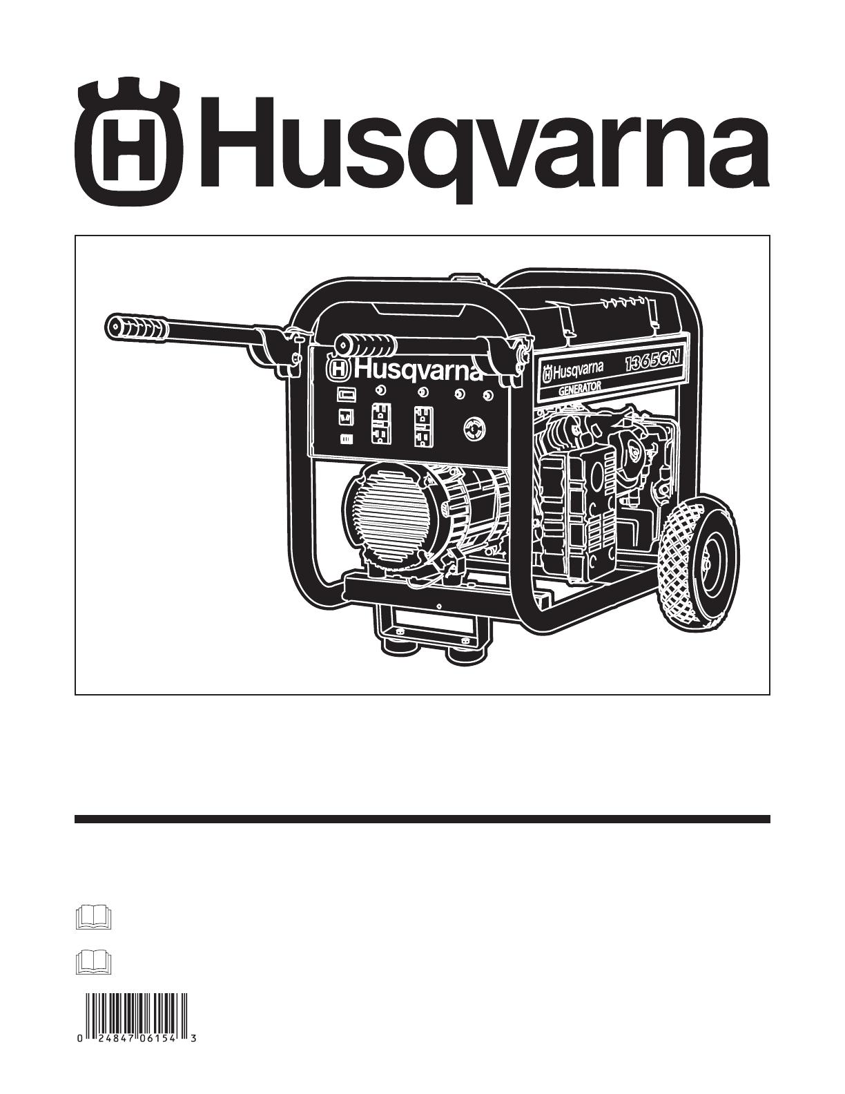
01935 1365GN

2
TABLE OF CONTENTS
Safety Rules. . . . . . . . . . . . . . . . . . . . . . . . . . . . . . . . . . . . 2-4
Know Your Generator. . . . . . . . . . . . . . . . . . . . . . . . . . . . . 5
Assembly. . . . . . . . . . . . . . . . . . . . . . . . . . . . . . . . . . . . . . 6-7
Operation . . . . . . . . . . . . . . . . . . . . . . . . . . . . . . . . . . . . 8-14
Maintenance . . . . . . . . . . . . . . . . . . . . . . . . . . . . . . . . . . . . 15
Storage . . . . . . . . . . . . . . . . . . . . . . . . . . . . . . . . . . . . . . . . 16
Troubleshooting. . . . . . . . . . . . . . . . . . . . . . . . . . . . . . . . . 17
Schematic/ Wiring Diagram . . . . . . . . . . . . . . . . . . . . . 18-19
Replacement Parts . . . . . . . . . . . . . . . . . . . . . . . . . . . . 20-24
Warranty . . . . . . . . . . . . . . . . . . . . . . . . . . . . . . . . . . . . . . 25
EQUIPMENT
DESCRIPTION
Read this manual carefully and become familiar
with your generator. Know the applications, the
limitations and any hazards involved.
This generator is an engine–driven, revolving field,
alternating current (AC) generator. It was designed to
supply electrical power for operating compatible electrical
lighting, appliances, tools and motor loads.The generator’s
revolving field is driven at about 3,600 rpm by a single-
cylinder engine.
CAUTION! DO NOT exceed the generator’s
wattage/amperage capacity. See “Don’t Overload
Generator”.
Every effort has been made to ensure that information in
this manual is accurate and current. However, we reserve
the right to change, alter or otherwise improve the product
and this document at any time without prior notice.
The Emission Control System for this generator is
warranted for standards set by the Environmental
Protection Agency and the California Air Resources Board.
For warranty information refer to the engine owner’s
manual.
SAFETY RULES
This is the safety alert symbol. It is used to
alert you to potential personal injury hazards.
Obey all safety messages that follow this
symbol to avoid possible injury or death.
The safety alert symbol ( ) is used with a signal word
(DANGER, CAUTION,WARNING), a pictorial and/or a
safety message to alert you to hazards. DANGER indicates
a hazard which, if not avoided, will result in death or
serious injury. WARNING indicates a hazard which, if not
avoided, could result in death or serious injury.
CAUTION indicates a hazard which, if not avoided, might
result in minor or moderate injury. CAUTION, when used
without the alert symbol, indicates a situation that could
result in equipment damage. Follow safety messages to
avoid or reduce the risk of injury or death.
Hazard Symbols and Meanings
Safety Rules
The engine exhaust from this product contains
chemicals known to the State of California to cause
cancer, birth defects, or other reproductive harm.
WARNING
Fire
Explosion
Toxic Fumes
Hot Surface
Electrocution
Kickback
Electrical Shock
Explosive Pressure
Chemical Burn
Copyright © 2005 Briggs & Stratton Power Products
Group, LLC. All rights reserved. No part of this material
may be reproduced or transmitted in any form by any
means without the express written permission of Briggs &
Stratton Power Products Group, LLC.
3
Safety Rules
• DO NOT allow any open flame, spark, heat, or lit cigarette
during and for several minutes after charging a battery.
• Wear protective goggles, rubber apron, and rubber gloves.
Storage batteries give off explosive hydrogen gas
during recharging.
Hydrogen gas stays near battery for a long time
after battery has been charged.
Slightest spark will ignite hydrogen and cause
explosion.
You can be blinded or severely injured.
Battery electrolyte fluid contains acid and is
extremely caustic.
Contact with battery fluid will cause severe
chemical burns.
DANGER
• This generator does not meet U. S. Coast Guard Regulation
33CFR-183 and should not be used on marine applications.
• Failure to use the appropriate U. S. Coast Guard approved
generator could result in death or serious injury and/or
property damage.
WARNING
• When using generator for backup power, notify utility
company. Use approved transfer equipment to isolate
generator from electric utility.
• Use a ground fault circuit interrupter (GFCI) in any damp or
highly conductive area, such as metal decking or steel work.
• DO NOT touch bare wires or receptacles.
• DO NOT use generator with electrical cords which are worn,
frayed, bare or otherwise damaged.
• DO NOT operate generator in the rain or wet weather.
• DO NOT handle generator or electrical cords while standing
in water, while barefoot, or while hands or feet are wet.
• DO NOT allow unqualified persons or children to operate or
service generator.
Generator produces powerful voltage.
Failure to isolate generator from power utility
can result in death or injury to electric utility
workers due to backfeed of electrical energy.
WARNING
• Operate generator ONLY outdoors.
• Keep exhaust gas from entering a confined area through
windows, doors, ventilation intakes or other openings.
• DO NOT operate generator inside any building or enclosure
(even if doors or windows are open), including the generator
compartment of a recreational vehicle (RV).
Running generator gives off carbon monoxide,
an odorless, colorless, poison gas.
Breathing carbon monoxide will cause nausea,
fainting or death.
WARNING
WHEN ADDING OR DRAINING FUEL
• Turn generator OFF and let it cool at least 2 minutes before
removing fuel cap. Loosen cap slowly to relieve pressure in
tank.
• Fill or drain fuel tank outdoors.
• DO NOT overfill tank.Allow space for fuel expansion.
• Keep fuel away from sparks, open flames, pilot lights, heat, and
other ignition sources.
• DO NOT light a cigarette or smoke.
WHEN STARTING EQUIPMENT
• Ensure spark plug, muffler, fuel cap and air cleaner are in place.
• DO NOT crank engine with spark plug removed.
• If fuel spills, wait until it evaporates before starting engine.
WHEN OPERATING EQUIPMENT
• Do not tip engine or equipment at angle which causes fuel to
spill.
• This generator is not for use in mobile equipment or marine
applications.
WHEN TRANSPORTING OR REPAIRING
EQUIPMENT
• Transport/repair with fuel tank EMPTY or with fuel shutoff
valve OFF.
• Disconnect spark plug wire.
WHEN STORING FUEL OR EQUIPMENT WITH FUEL
IN TANK
• Store away from furnaces, stoves, water heaters, clothes
dryers or other appliances that have pilot light or other
ignition source because they can ignite fuel vapors.
Fuel and its vapors are extremely flammable and
explosive.
Fire or explosion can cause severe burns or
death.
WARNING

4
• Use generator only for intended uses.
• If you have questions about intended use, ask your Husqvarna
dealer or contact customer service at 1-877-224-0458.
• Operate generator only on level surfaces.
• DO NOT expose generator to excessive moisture, dust, dirt,
or corrosive vapors.
• DO NOT insert any objects through cooling slots.
• If connected devices overheat, turn them off and disconnect
them from generator.
• Shut off generator if:
-electrical output is lost;
-equipment sparks, smokes, or emits flames;
-unit vibrates excessively.
Improper treatment of generator can damage it and
shorten its life.
CAUTION
Safety Rules
• When starting engine, pull cord slowly until resistance is felt
and then pull rapidly to avoid kickback.
• NEVER start or stop engine with electrical devices plugged in
and turned on.
Rapid retraction of starter cord (kickback) will
pull hand and arm toward engine faster than
you can let go.
Broken bones, fractures, bruises or sprains could
result.
WARNING
WHEN ADJUSTING OR MAKING REPAIRS TO YOUR
GENERATOR
• Disconnect the spark plug wire from the spark plug and place
the wire where it cannot contact spark plug.
WHEN TESTING FOR ENGINE SPARK
• Use approved spark plug tester.
• DO NOT check for spark with spark plug removed.
Unintentional sparking can result in fire or
electric shock.
WARNING
• DO NOT touch hot surfaces and avoid hot exhaust gases.
• Allow equipment to cool before touching.
• The generator must be at least 5 feet from structures having
combustible walls and/or other combustible materials.
• Keep at least 3 feet of clearance on all sides of generator for
adequate cooling, maintenance and servicing.
• Reflective exhaust heat may damage fuel tank causing fire.
• Code of Federal Regulation (CFR) Title 36 Parks, Forests, and
Public Property require equipment powered by an internal
combustion engine to have a spark arrester, maintained in
effective working order, complying to USDA Forest service
standard 5100-1C or later revision. In the State of California a
spark arrester is required under section 4442 of the California
Public resources code. Other states may have similar laws.
Running engines produce heat.Temperature of
muffler and nearby areas can reach or exceed
150°F (65°C).
Severe burns can occur on contact.
Combustible debris, such as leaves, grass, brush,
ect. can catch fire.
WARNING
• DO NOT tamper with governed speed. Generator supplies
correct rated frequency and voltage when running at governed
speed.
• DO NOT modify generator in any way.
Excessively high operating speeds increase risk of injury
and damage to generator.
Excessively low speeds impose a heavy load.
CAUTION
• See “Don’t Overload Generator”.
• Start generator and let engine stabilize before connecting
electrical loads.
• Connect electrical loads in OFF position, then turn ON for
operation.
• Turn electrical loads OFF and disconnect from generator
before stopping generator.
Exceeding generators wattage/amperage capacity can
damage generator and/or electrical devices connected
to it.
CAUTION
5
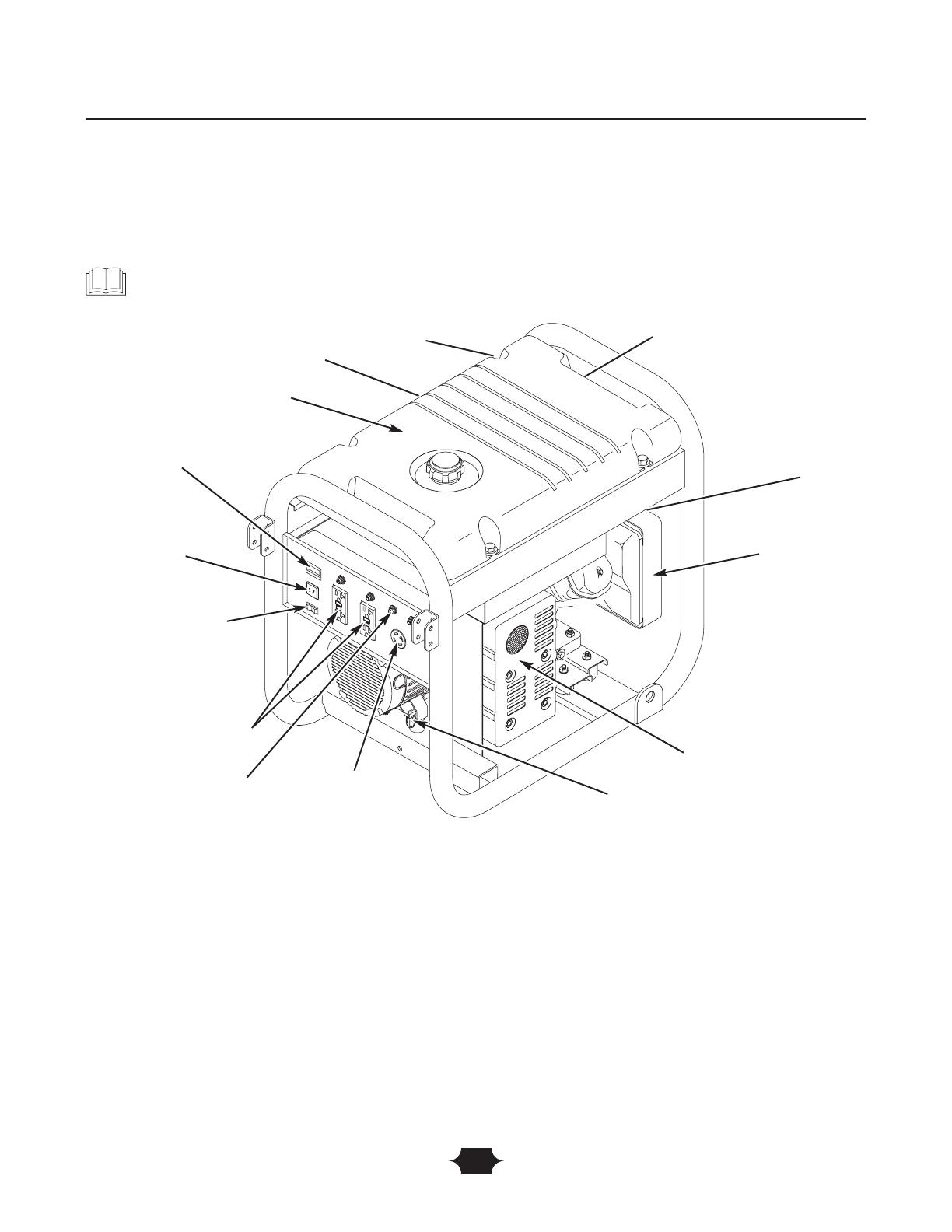
12 Volt DC,10 Amp Receptacle — Recharge a discharged
12 Volt automotive type battery through this receptacle.
120 Volt AC, 20 Amp GFCI Duplex Receptacles —
May be used to supply electrical power for the operation
of 120 Volt AC, 20 Amp, single phase, 60 Hz electrical,
lighting, appliance, tool and motor loads.
120/240 Volt AC, 30 Amp Locking Receptacle — May
be used to supply electrical power for the operation of
120 and/or 240 Volt AC, 30 Amp, single phase, 60 Hz
electrical, lighting, appliance, tool and motor loads.
Air Cleaner —
Protects engine by filtering dust and debris
out of intake air.
Choke Lever — Used when starting a cold engine.
Circuit Breakers (AC) — Push to reset circuit breakers
are provided to protect the generator against electrical
overload.
Fuel Tank — Capacity of seven (7) U.S. gallons.
Grounding Fastener — Consult your local agency having
jurisdiction for grounding requirements in your area.
Hour Meter — Displays and records how many hours
your generator has run (up to 9,999.9).
Idle Control Switch — The idle control runs the engine at
normal (high) speeds when there is a load present and runs
the engine at idle (low) speeds when a load is not present.
Oil Fill — Add engine oil here.
Recoil Starter — Used to start the engine.
Engine Switch — Set this switch to "On" before using
recoil starter. Set switch to "Off" to switch off engine.
Spark Arrester Muffler — Exhaust muffler lowers
engine noise and is equipped with a spark arrester screen.
KNOW YOUR GENERATOR
Read this owner’s manual and safety rules before operating your generator.
Compare the illustrations with your generator, to familiarize yourself with the locations of various controls and
adjustments. Save this manual for future reference.
120 Volt AC, 20 Amp GFCI
Duplex Receptacles
Fuel Tank
Choke Lever
Recoil Starter
Engine Switch
Circuit
Breakers (AC)
120/240 Volt AC,
30 Amp Receptacle
Spark Arrester Muffler
Air Cleaner
Grounding
Fastener
Oil Fill
Idle Control Switch
Hour Meter
12 Volt DC,10 Amp
Receptacle
Features and Controls

6
ASSEMBLY
Your generator requires some assembly and is ready for
use after it has been properly serviced with the
recommended oil and fuel.
If you have any problems with the assembly of your
generator, please call the generator helpline at
1–877–224–0458. If calling for assistance, please have the
model, revision, and serial number from the data tag available.
Remove Generator From Carton
1. Set the carton on a rigid flat surface.
2. Remove everything from carton except generator.
3. Open carton completely by cutting each corner from
top to bottom.
4. Leave generator on carton to install wheel kit.
Carton Contents
Check all contents. If any parts are missing or damaged, call
the generator helpline at 1–877–224–0458.
• The generator
• Generator and engine owner’s manuals
• Locking 30 Amp plug
• Battery charge cables
• Engine oil
• Wheel kit
Install Wheel Kit
The wheel kit is designed to greatly improve the portability
of your generator.
NOTE: Wheel kit is not intended for over-the-road use.
You will need a socket wrench with 1/2" or 13mm sockets
and a needle-nose pliers to install this kit.
Refer to Figure 1 and install the wheel kit as follows:
1. Place the bottom of the generator frame on a flat, even
surface.Temporarily place unit on blocks to ease assembly.
2. Slide axle through both axle mounting brackets on
cradle frame, as shown in Figure 1.
3. Slide a wheel over the axle.
NOTE: Be sure to install both wheels with the air
pressure valve on the outboard side.
4. Place the e-ring onto the groove in the axle.You may
add the flat washer if desired.
Assembly
Support Leg
Nut
Axle
Flat Washer
Wheel
E-Ring
Figure 1 — Install Wheel Kit
20 mm Cap Screw
Nut
3/4” Cap Screw
Vibration Mount
Use existing hardware
to attach left side of
support leg to unit
Nut
Handle Pin
Handle
Flat Washer
Nylon Washer
45 mm Cap Screw
Nylon Washer
7
5. Place one end of the needle nose pliers on the bottom
of the axle and the other end of the pliers on top of
the e-ring. Seat the e-ring by pressing the pliers closed.
6. Repeat step 3 through 5 to secure second wheel.
7. Remove the temporary blocks.
8. Attach the vibration mounts to the support leg with
3/4” capscrews and lock nuts.
9. To aid support leg assembly, rest generator on cradle,
engine end down. Remove the existing hardware from
the left unit vibration mount with 13mm wrench. Use
the same hardware to attach the support leg.
10. Attach the other side of the support leg with a 20 mm
cap screw and lock nut. Rest generator on wheels and
support leg.
11. Attach handles to handle brackets on generator frame,
as shown in Figure 1, with 45 mm capscrews, flat
washers, nylon washers, and lock nuts.
12. Loop handle pins to generator frame as shown in
Figure 1. Raise handles and insert handle pins to move
generator.
13. Check each fastener to ensure it is secure and the
tires are inflated between 15-40 PSI.
BEFORE STARTING THE
ENGINE
Add Engine Oil
• Place generator on a level surface.
• Refer to engine owner’s manual and follow oil
recommendations and instructions.
NOTE: Check oil often during engine break–in. Refer to
engine owner’s manual for recommendations.
NOTE: The generator assembly rotates on a prelubricated
and sealed ball bearing that requires no additional
lubrication for the life of the bearing.
Add Fuel
NOTE: This gasoline engine is certified to operate on
gasoline. Exhaust Emission Control System: EM (Engine
Modifications).
1. Use clean, fresh, regular UNLEADED gasoline with a
minimum of 85 octane. DO NOT use fuel which
contains Methanol. DO NOT mix oil with fuel.
2. Clean area around fuel fill cap, remove cap.
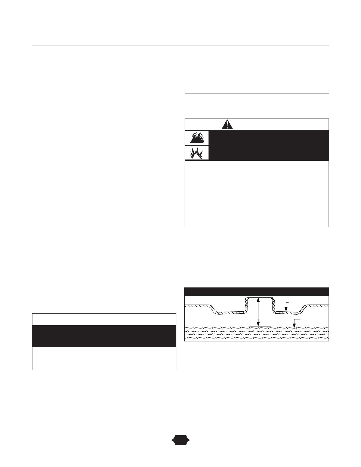
3. Slowly add regular unleaded fuel to fuel tank. Be careful
not to overfill.Allow about 1.5" of tank space for fuel
expansion (Figure 2).
4. Install fuel cap and wipe up any spilled fuel.
Assembly
CAUTION
• Refer to engine manual for oil fill information.
• Damage to equipment resulting from failure to follow this
instruction will void warranty.
Any attempt to crank or start the engine before it has
been properly filled with the recommended oil will result
in equipment failure.
WHEN ADDING FUEL
• Turn generator OFF and let it cool at least 2 minutes before
removing fuel cap. Loosen cap slowly to relieve pressure in
tank.
• Fill fuel tank outdoors.
• DO NOT overfill tank.Allow space for fuel expansion.
• Keep fuel away from sparks, open flames, pilot lights, heat, and
other ignition sources.
• DO NOT light a cigarette or smoke.
Fuel and its vapors are extremely flammable and
explosive.
Fire or explosion can cause severe burns or
death.
WARNING
Fuel
Tank
1.5” Air Space
Figure 2 - Fuel Expansion
8
USING THE GENERATOR
System Ground
The generator has a system ground that connects the
generator frame components to the ground terminals on
the AC output receptacles.The system ground is connected
to the AC neutral wire (the neutral is bonded to the
generator frame).
Special Requirements
There may be Federal or State Occupational Safety and
Health Administration (OSHA) regulations, local codes, or
ordinances that apply to the intended use of the generator.
Please consult a qualified electrician, electrical inspector, or
the local agency having jurisdiction.
• In some areas, generators are required to be registered
with local utility companies.
• If the generator is used at a construction site, there may
be additional regulations which must be observed.
Connecting to a Building’s Electrical
System
Connections for standby power to a building’s electrical
system must be made by a qualified electrician.The
connection must isolate the generator power from utility
power, and must comply with all applicable laws and
electrical codes.
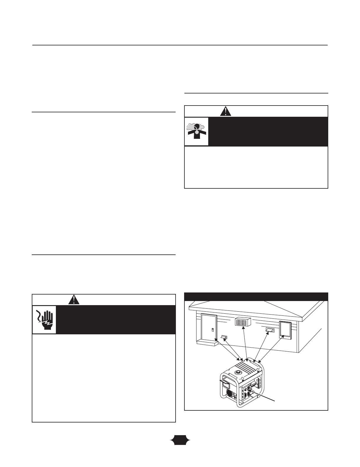
Generator Location
Generator Clearance
The generator must be at least 5 ft. (152 cm) from
structures having combustible walls and/or other
combustible materials. Leave at least 3 ft. (92 cm) all around
generator including overhead, for adequate cooling,
maintenance and servicing.
Place generator in a well ventilated area, which will allow
for removal of deadly exhaust gas. DO NOT place
generator where exhaust gas could accumulate and enter
inside or be drawn into a potentially occupied building.
Ensure exhaust gas is kept away from any windows, doors,
ventilation intakes or other openings that can allow exhaust
gas to collect in a confined area (Figure 3). Prevailing winds
and air currents should be taken into consideration when
positioning generator.
Operation
Figure 3 — Generator Clearance
Exhaust Port
Typical Generator Shown
• When using generator for backup power, notify utility
company. Use approved transfer equipment to isolate
generator from electric utility.
• Use a ground fault circuit interrupter (GFCI) in any damp or
highly conductive area, such as metal decking or steel work.
• DO NOT touch bare wires or receptacles.
• DO NOT use generator with electrical cords which are worn,
frayed, bare or otherwise damaged.
• DO NOT operate generator in the rain.
• DO NOT handle generator or electrical cords while standing
in water, while barefoot, or while hands or feet are wet.
• DO NOT allow unqualified persons or children to operate or
service generator.
Generator produces powerful voltage.
Failure to isolate generator from power utility
can result in death or injury to electric utility
workers due to backfeed of electrical energy.
WARNING
• Operate generator ONLY outdoors.
• Keep exhaust gas from entering a confined area through
windows, doors, ventilation intakes or other openings.
• DO NOT operate generator inside any building or enclosure
(even if doors or windows are open), including the generator
compartment of a recreational vehicle (RV).
Running generator gives off carbon monoxide,
an odorless, colorless, poison gas.
Breathing carbon monoxide will cause nausea,
fainting or death.
WARNING

9
OPERATING THE
GENERATOR
Starting the Engine
Disconnect all electrical loads from the generator. Use the
following start instruction steps by numerical order:
1. Make sure unit is on a level surface.
IMPORTANT: Failure to start and operate unit on a level
surface will cause the unit not to start or shut down during
operation.
2. Turn fuel valve to “On” position (Figure 4).The fuel
valve handle should be vertical (pointing toward
ground) for fuel to flow.
3. Make sure Idle Control switch is in “Off” position
(Figure 5).
4. Start engine according to instructions given in engine
owner’s manual.
NOTE: If engine starts after 3 pulls but fails to run, or if
unit shuts down during operation, make sure unit is on a
level surface and check for proper oil level in crankcase.
This unit may be equipped with a low oil protection device.
See engine manual.
Connecting Electrical Loads
• Let engine stabilize and warm up for a few minutes after
starting.
• Plug in and turn on the desired 120 and/or 240 Volt AC,
single phase, 60 Hz electrical loads.
• DO NOT connect 240 Volt loads to the 120 Volt duplex
receptacles.
• DO NOT connect 3–phase loads to the generator.
• DO NOT connect 50 Hz loads to the generator.
• DO NOT OVERLOAD THE GENERATOR. See
“Don’t Overload Generator”.
Operation
Fuel Valve is shown
in the “On” position
Figure 4 — Fuel Valve
Figure 5 — Idle Control Switch
• See “Don’t Overload Generator”.
• Start generator and let engine stabilize before connecting
electrical loads.
• Connect electrical loads in OFF position, then turn ON for
operation.
• Turn electrical loads OFF and disconnect from generator
before stopping generator.
Exceeding generator’s wattage/amperage capacity can
damage generator and/or electrical devices connected to it.
CAUTION
• When starting engine, pull cord slowly until resistance is felt
and then pull rapidly to avoid kickback.
• NEVER start or stop engine with electrical devices plugged in
and turned on.
Rapid retraction of starter cord (kickback) will
pull hand and arm toward engine faster than
you can let go.
Broken bones, fractures, bruises or sprains could
result.
WARNING
• DO NOT touch hot surfaces and avoid hot exhaust gases.
• Allow equipment to cool before touching.
• The generator must be at least 5 feet from structures having
combustible walls and/or other combustible materials.
• Keep at least 3 feet of clearance on all sides of generator for
adequate cooling, maintenance and servicing.
• Reflective exhaust heat may damage fuel tank causing fire.
• Code of Federal Regulation (CFR) Title 36 Parks, Forests, and
Public Property require equipment powered by an internal
combustion engine to have a spark arrester, maintained in
effective working order, complying to USDA Forest service
standard 5100-1C or later revision. In the State of California a
spark arrester is required under section 4442 of the California
Public resources code. Other states may have similar laws.
Running engines produce heat.Temperature of
muffler and nearby areas can reach or exceed
150°F (65°C).
Severe burns can occur on contact.
Combustible debris, such as leaves, grass, brush,
ect. can catch fire.
WARNING
10
Stopping the Engine
1. Unplug ALL electrical loads from generator panel
receptacles. NEVER start or stop engine with electrical
devices plugged in and turned ON.
2. Move idle control switch to “Off” position.
3. Let engine run at no-load for several minutes to
stabilize internal temperatures of engine and generator.
4. Turn engine off according to instructions given in the
engine owner’s manual.
5. Move fuel valve to “Off” position.
Operating Automatic Idle Control
This switch is designed to greatly improve fuel economy.
When this switch is turned ON, the engine will only
run at its normal high governed engine speed when an
electrical load is connected.When an electrical load is
removed, the engine will run at a reduced speed. With the
switch off, the engine will run at the normal high engine
speed. Always have the switch off when starting and
stopping the engine.
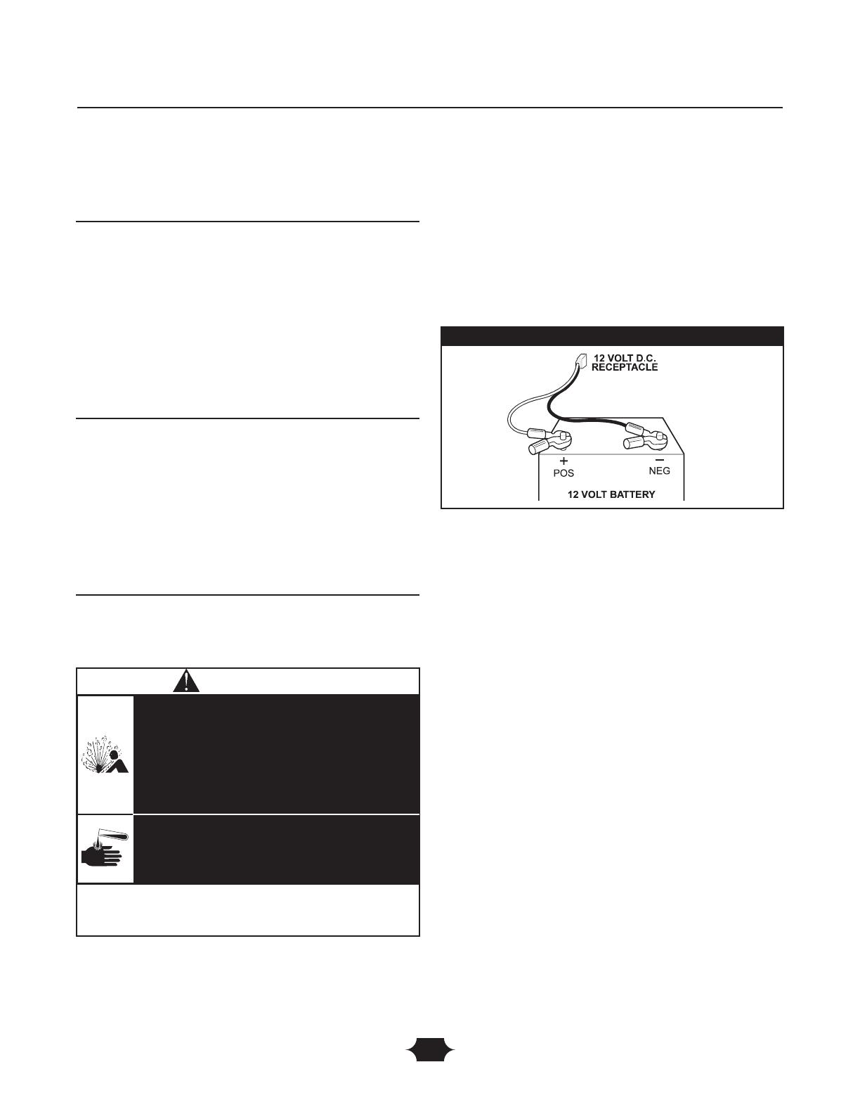
Charging a Battery
Your generator has the capability of recharging a discharged
12 Volt automotive or utility style storage battery. DO
NOT use the unit to charge any 6 Volt batteries. DO NOT
use the unit to crank an engine having a discharged battery.
To recharge 12 Volt batteries, proceed as follows:
1. Check fluid level in all battery cells. If necessary, add
ONLY distilled water to cover separators in battery
cells. DO NOT use tap water.
2. If battery is equipped with vent caps, make sure they
are installed and are tight.
3. If necessary, clean battery terminals.
4. Connect battery charge cable connector plug to panel
receptacle identified by the words “12-VOLTS D.C.”.
5. Connect battery charge cable clamp with red handle
to the positive (+) battery terminal (Figure 6).
6. Connect battery charge cable clamp with black handle
to the negative (–) battery terminal (Figure 6).
7. Start engine. Let engine run while battery recharges.
8. When battery has charged, shut down engine
NOTE: Use an automotive hydrometer to test battery state
of charge and condition. Follow the hydrometer
manufacturer’s instructions carefully. Generally, a battery is
considered to be at 100% state of charge when specific gravity
of its fluid (as measured by hydrometer) is 1.260 or higher.
COLD WEATHER
OPERATION
Under certain weather conditions (temperatures below
40°F [4°C] combined with high humidity), your generator
may experience icing of the carburetor and/or the
crankcase breather system.To reduce this problem, you
need to perform the following:
1. Make sure generator has clean, fresh fuel.
2. Open fuel valve (turn valve to open position).
3. Use SAE 5W-30 oil (synthetic preferred, see engine
manual).
4. Check oil level daily or after every eight (8) hours of
operation.
5. Maintain generator following “Maintenance Schedule”
in engine manual.
6. Shelter unit from elements.
Operation
Figure 6 — Battery Connections
• DO NOT allow any open flame, spark, heat, or lit cigarette
during and for several minutes after charging a battery.
• Wear protective goggles, rubber apron, and rubber gloves.
Storage batteries give off explosive hydrogen gas
during recharging.
Hydrogen gas stays near battery for a long time
after battery has been charged.
Slightest spark will ignite hydrogen and cause
explosion.
You can be blinded or severely injured.
Battery electrolyte fluid contains acid and is
extremely caustic.
Contact with battery fluid will cause severe
chemical burns.
DANGER

11
In an emergency, use the original shipping carton as a
temporary shelter:
7. Cut off all carton flaps.
8. Cut out one long side of carton to expose muffler side
of unit as shown in Figure 7.
IMPORTANT: The generator must be at least 5 ft. (1.5 m)
from structures having combustible walls and/or other
combustible materials. Leave at least 3 ft. (1 m) all around
generator including overhead, for adequate cooling,
maintenance and servicing.
9. Cut appropriate slots to access receptacles of unit.
10. Start unit, then place carton over it.
NOTE: Remove shelter when temperatures are above
40°F [4°C].
For a more permanent shelter, build a structure that will
enclose three sides and the top of the generator.
7. Make sure entire muffler-side of generator is exposed,
as shown in Figure 7.
IMPORTANT: The generator must be at least 5 ft. (1.5 m)
from structures having combustible walls and/or other
combustible materials. Leave at least 3 ft. (1 m) all around
generator including overhead, for adequate cooling,
maintenance and servicing.
8. Face exposed end away from wind and elements.
9. Structure should hold enough heat created by the
generator to prevent icing problem.
10. Start and run engine outdoors.
11. Keep exhaust gas from entering a confined area
through windows, doors, ventilation intakes or other
openings.
12. DO NOT enclose generator any more than shown in
Figure 7.
13. Remove shelter when temperatures are above 40°F
[4°C].
14. Turn engine OFF and let cool two (2) minutes before
refueling.
Operation
Figure 7 — Permanent Cold Weather Shelter
Wind
• DO NOT touch hot surfaces and avoid hot exhaust gases.
• Allow equipment to cool before touching.
• The generator must be at least 5 feet from structures having
combustible walls and/or other combustible materials.
• Keep at least 3 feet of clearance on all sides of generator for
adequate cooling, maintenance and servicing.
• Reflective exhaust heat may damage fuel tank causing fire.
• Remove shelter when temperatures are above 40°F [4°C].
Running engines produce heat.Temperature of
muffler and nearby areas can reach or exceed
150°F (65°C).
Severe burns can occur on contact.
Combustible debris, such as leaves, grass, brush,
etc. can catch fire.
WARNING
• Operate generator ONLY outdoors.
• Keep exhaust gas from entering a confined area through
windows, doors, ventilation intakes or other openings.
• DO NOT operate generator inside any building or enclosure
(even if doors or windows are open), including the generator
compartment of a recreational vehicle (RV).
Running generator gives off carbon monoxide,
an odorless, colorless, poison gas.
Breathing carbon monoxide can cause nausea,
fainting or death.
WARNING
12
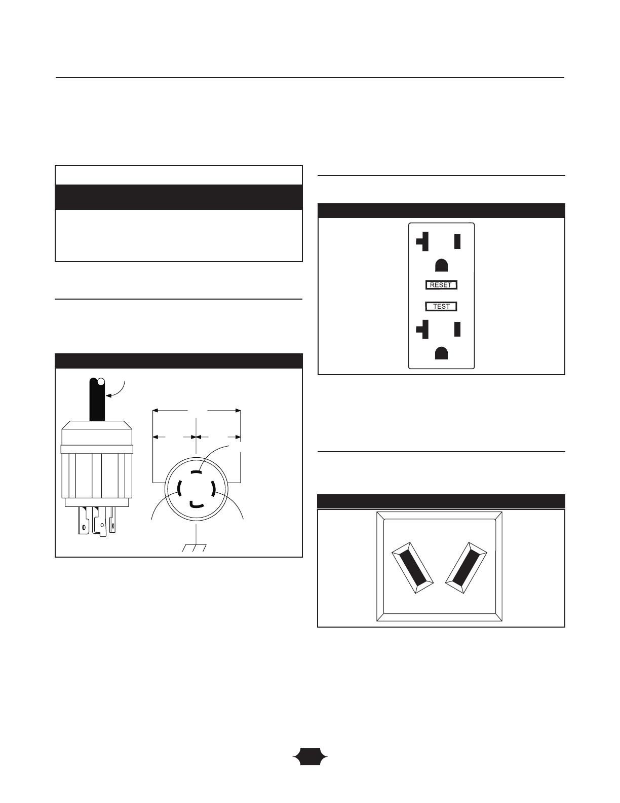
RECEPTACLES
120/240 Volt AC, 30 Amp, Locking
Receptacle
Use a NEMA L14–30 plug with this receptacle. Connect a
4–wire cord set rated for 250 Volt AC loads at 30 Amps (or
greater) (Figure 8).You can use the same 4–wire cord if you
plan to run a 120 Volt load.
This receptacle powers 120/240 Volt AC, 60 Hz, single
phase loads requiring up to 6,500 watts of power (6.5 kW)
at 27.1 Amps for 120 Volts or 240 Volts.The outlet is
protected by a push–to–reset circuit breaker.
120 Volt AC, 20 Amp, GFCI Duplex
Receptacles
Each duplex receptacle (Figure 9) is protected against
overload by a push–to–reset circuit breaker.
Use each receptacle to operate 120 Volt AC, single–phase,
60 Hz electrical loads requiring up to 2,400 watts (2.4 kW)
at 20 Amps of current. Use cord sets that are rated for
125 Volt AC loads at 20 Amps (or greater).
12 Volt DC, 10 Amp Receptacle
This receptacle (Figure 10) allows you to recharge a 12 Volt
automotive or utility style storage battery with the battery
charge cables provided.
This receptacle can not recharge 6 Volt batteries and can
not be used to crank an engine having a discharged battery.
See “Charging a Battery” on page 10 before attempting to
recharge a battery.This outlet is protected by a 10 Amp
self-resetting circuit breaker.
Operation
Figure 8 — 120/240 Volt AC, 30 Amp Receptacle
4-Wire Cord Set
240V
120V
120V
W (Neutral)
X (Hot)
Y (Hot)
NEMA L14-30
Ground (Green)
Figure 9 — 120 Volt, 20 Amp GFCI Duplex Receptacle
Figure 10 — 12 Volt DC, 10 Amp Receptacle
• NEVER attempt to power a device requiring more amperage
than generator or receptacle can supply.
• DO NOT overload the generator. See “Don’t Overload
Generator”.
Receptacles may be marked with rating value greater
than generator output capacity.
CAUTION
13
Ground Fault Protection
This unit is equipped with a Ground Fault Circuit
Interrupter (GFCI).This device meets applicable federal,
state and local codes.
The GFCI protects against electrical shock that may be
caused if your body becomes a path which electricity
travels to reach the ground.This could happen if you touch
a “Live” appliance or wire, or are touching plumbing or
other materials that connect to the ground.
When protected by a GFCI, one may still feel a shock, but
the GFCI should cut current off quickly enough so that a
person in normal health should not suffer any serious
electrical injury.
Testing the GFCI
Test your GFCI outlet every month and before use, as
follows:
• Push the black “Test” button.The red “Reset” button
should pop out, which should allow no power to reach
the outlet. Use a test lamp in each outlet to test this.
• If the GFCI tests good, restore power by pressing the
“Reset” button firmly until it is fully in place and locks in
that position. If the GFCI outlet does not reset
properly, do not use the outlet. Call a local service
center.
• If the GFCI trips by itself at any time, reset and test the
outlet. If the reset button does pop out when the
test button is pressed, do not use the outlet. Call
a local service center.
Operation
• The GFCI will not protect you against the following situations:
-Line-to-line shocks;
-Current overloads or line-to-line short circuits.
• The fuse or circuit breaker at the control panel must provide
such protection.
Generator produces powerful voltage.
WARNING
• DO NOT use any outlets on the circuit.
• Call a qualified electrician.
The “Reset” button does not pop out or the test lamp
remains lit when the “Reset” button is popped out.
CAUTION
14
DON'T OVERLOAD
GENERATOR
Capacity
You must make sure your generator can supply enough
rated (running) and surge (starting) watts for the items you
will power at the same time. Follow these simple steps:
1. Select the items you will power at the same time.
2. Total the rated (running) watts of these items.This is
the amount of power your generator must produce to
keep your items running. See Figure 11.
3. Estimate how many surge (starting) watts you will
need. Surge wattage is the short burst of power
needed to start electric motor-driven tools or
appliances such as a circular saw or refrigerator.
Because not all motors start at the same time, total
surge watts can be estimated by adding only the
item(s) with the highest additional surge watts to the
total rated watts from step 2.
Example:
Total Rated (Running) Watts = 3075
Highest Additional Surge Watts = 1800
Total Generator Output Required = 4875
Power Management
To prolong the life of your generator and attached devices,
it is important to take care when adding electrical loads to
your generator.There should be nothing connected to the
generator outlets before starting it's engine.The correct
and safe way to manage generator power is to sequentially
add loads as follows:
1. With nothing connected to the generator, start the
engine as described in this manual.
2. Plug in and turn on the first load, preferably the largest
load you have.
3. Permit the generator output to stabilize (engine runs
smoothly and attached device operates properly).
4. Plug in and turn on the next load.
5. Again, permit the generator to stabilize.
6. Repeat steps 4 and 5 for each additional load.
NEVER add more loads than the generator capacity.Take
special care to consider surge loads in generator capacity,
as described above.
*Wattages listed are approximate only. Check tool or
appliance for actual wattage.
Tool or Appliance
Rated (Running)
Watts
Additional Surge
(Starting) Watts
Window Air
Conditioner
1200 1800
Refrigerator 800 1600
Deep Freezer 500 500
Television 500 -
Light (75 Watts) 75 -
3075 Total
Running Watts
1800 Highest
Surge Watts
Tool or Appliance
Rated*
(Running)
Watts
Additional
Surge
(Starting)
Watts
Essentials
Light Bulb - 75 watt 75 -
Deep Freezer 500 500
Sump Pump 800 1200
Refrigerator/Freezer - 18 Cu. Ft. 800 1600
Water Well Pump - 1/3 HP 1000 2000
Heating/Cooling
Window AC - 10,000 BTU 1200 1800
Window Fan 300 600
Furnace Fan Blower - 1/2 HP 800 1300
Kitchen
Microwave Oven - 1000 Watt 1000 -
Coffee Maker 1500 -
Electric Stove - Single Element 1500 -
Hot Plate 2500 -
Family Room
DVD/CD Player 100 -
VCR 100 -
Stereo Receiver 450 -
Color Television - 27” 500 -
Personal Computer w/17” monitor 800 -
Other
Security System 180 -
AM/FM Clock Radio 300 -
Garage Door Opener - 1/2 HP 480 520
Electric Water Heater - 40 Gallon 4000 -
DIY/Job Site
Quartz Halogen Work Light 1000 -
Airless Sprayer - 1/3 HP 600 1200
Reciprocating Saw 960 960
Electric Drill - 1/2 HP 1000 1000
Circular Saw - 7 1/4” 1500 1500
Miter Saw - 10” 1800 1800
Table Planer - 6” 1800 1800
Table Saw/Radial Arm Saw - 10” 2000 2000
Air Compressor - 1-1/2 HP 2500 2500
Figure 11 - Wattage Reference Chart
Operation

15
SPECIFICATIONS
Starting Wattage . . . . . . . . . . . . . . . . . . . . . . .8,125 watts
Wattage . . . . . . . . . . . . . . . . . . . . . . . . . . . . .6,500 watts
AC Load Current:
At 120 Volts . . . . . . . . . . . . . . . . . . . . . . . . .54.2 Amps
At 240 Volts . . . . . . . . . . . . . . . . . . . . . . . . .27.1 Amps
Phase . . . . . . . . . . . . . . . . . . . . . . . . . . . . . . . . . .1–phase
Rated Frequency . . . . . . . . . . . . . . . . . . . . . . . . .60 Hertz
Fuel Tank Capacity . . . . . . . . . . . . . . . . . . . . 7 U.S. gallons
Shipping Weight . . . . . . . . . . . . . . . . . . . . . . . . . . 205 lbs.
GENERAL MAINTENANCE
RECOMMENDATIONS
The Owner/Operator is responsible for making sure that
all periodic maintenance tasks are completed on a timely
basis; that all discrepancies are corrected; and that the unit
is kept clean and properly stored. NEVER operate a
damaged or defective generator.
NOTE: Should you have questions about replacing
components on your Husqvarna generator, please call
1-877-224-0458 for assistance.
Engine Maintenance
See engine owner’s manual for instructions.
KEEP OUT OF REACH OF CHILDREN. DON'T
POLLUTE. CONSERVE RESOURCES. RETURN
USED OIL TO COLLECTION CENTERS.
Generator Maintenance
Generator maintenance consists of keeping the unit clean
and dry. Operate and store the unit in a clean dry
environment where it will not be exposed to excessive
dust, dirt, moisture or any corrosive vapors. Cooling air
slots in the generator must not become clogged with dirt,
leaves or any other foreign material.
NOTE: DO NOT use a garden hose to clean generator.
Water can enter engine fuel system and cause problems. In
addition, if water enters generator through cooling air slots,
some of the water will be retained in voids and cracks of
the rotor and stator winding insulation.Water and dirt
buildup on the generator internal windings will eventually
decrease the insulation resistance of these windings.
Generator Cleaning
• Use a damp cloth to wipe exterior surfaces clean.
• Use a soft bristle brush to loosen caked on dirt or oil.
• Use a vacuum cleaner to pick up loose dirt and debris.
• Use low pressure air (not to exceed 25 psi) to blow
away dirt. Inspect cooling air slots and opening on
generator.These openings must be kept clean and
unobstructed.
• Used motor oil has been shown to cause skin cancer in
certain laboratory animals.
• Thoroughly wash exposed areas with soap and water.
Avoid prolonged or repeated skin contact with used
motor oil.
CAUTION
• DO NOT expose generator to excessive moisture, dust, dirt,
or corrosive vapors.
• DO NOT insert any objects through cooling slots.
Improper treatment of generator can damage it and
shorten its life.
CAUTION
Maintenance
WHEN ADJUSTING OR MAKING REPAIRS TO YOUR
GENERATOR
• Disconnect the spark plug wire from the spark plug and place
the wire where it cannot contact spark plug.
WHEN TESTING FOR ENGINE SPARK
• Use approved spark plug tester.
• DO NOT check for spark with spark plug removed.
Unintentional sparking can result in fire or
electric shock.
WARNING

16
STORAGE
The generator should be started at least once every seven
days and allowed to run at least 30 minutes. If this cannot
be done and you must store the unit for more than
30 days, use the following guidelines to prepare it for
storage.
Generator Storage
• Clean the generator as outlined in “Generator Cleaning”.
• Check that cooling air slots and openings on generator
are open and unobstructed.
Engine Storage
See engine owner’s manual for instructions.
Other Storage Tips
• To prevent gum from forming in fuel system or on
essential carburetor parts, add fuel stabilizer into fuel
tank and fill with fresh fuel. Run the unit for several
minutes to circulate the additive through the carburetor.
The unit and fuel can then be stored for up to
24 months. Fuel stabilizer can be purchased locally.
• DO NOT store fuel from one season to another unless
it has been treated as described above.
• Replace fuel container if it starts to rust. Rust and/or dirt
in fuel can cause problems if it's used with this unit.
• Store unit in a clean and dry area.
Storage
• DO NOT place a storage cover over a hot generator.
• Let equipment cool for a sufficient time before placing the
cover on the equipment.
Storage covers can be flammable.
WARNING

17
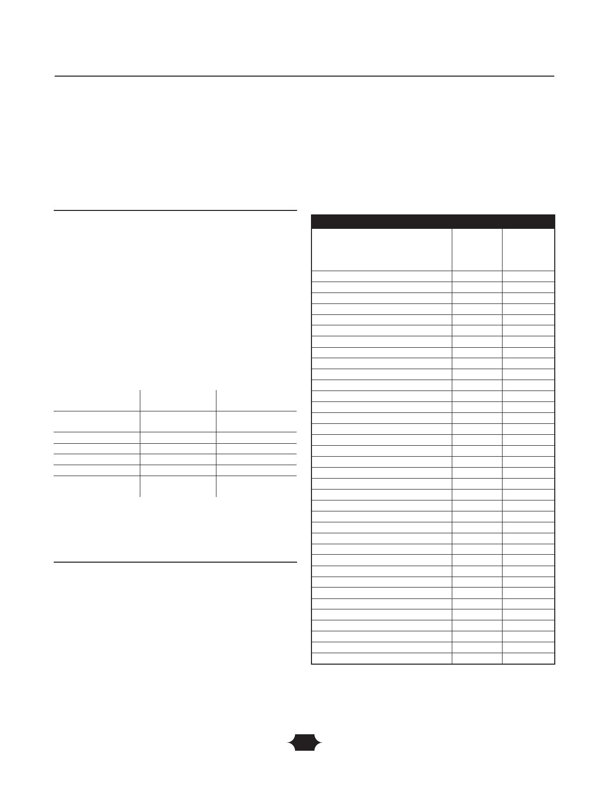
TROUBLESHOOTING
Troubleshooting
Problem Cause Correction
No AC output is available, but
generator is running.
1. One of the circuit breakers is
open.
2. Fault in generator.
3. Poor connection or defective cord
set.
4. Connected device is bad.
1. Reset circuit breaker.
2. Contact Authorized service facility.
3. Check and repair.
4. Connect another device that is in
good condition.
Generator runs good at no-load
but "bogs" down" when loads are
connected.
1. Short circuit in a connected load.
2. Generator is overloaded.
3. Shorted generator circuit.
1. Disconnect shorted electrical load.
2. See "Don't Overload Generator".
3. Contact Authorized service facility.
Generator will not start; or starts
and runs rough.
Low oil level. Fill crankcase to proper level or place
generator on level surface.
Generator shuts down during
operation.
1. Out of gasoline.
2. Low oil level.
1. Fill fuel tank.
2. Fill crankcase to proper level or
place generator on level surface.
Generator lacks power. Load is too high. See "Don't Overload Generator".
18
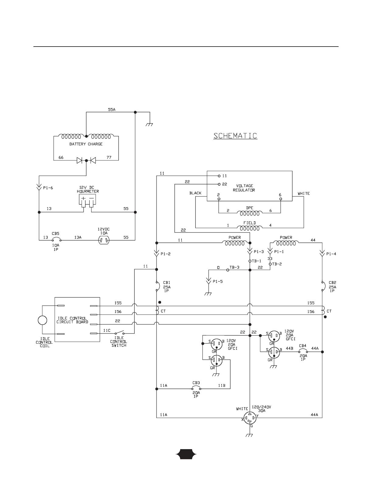
SCHEMATIC
Schematic
19
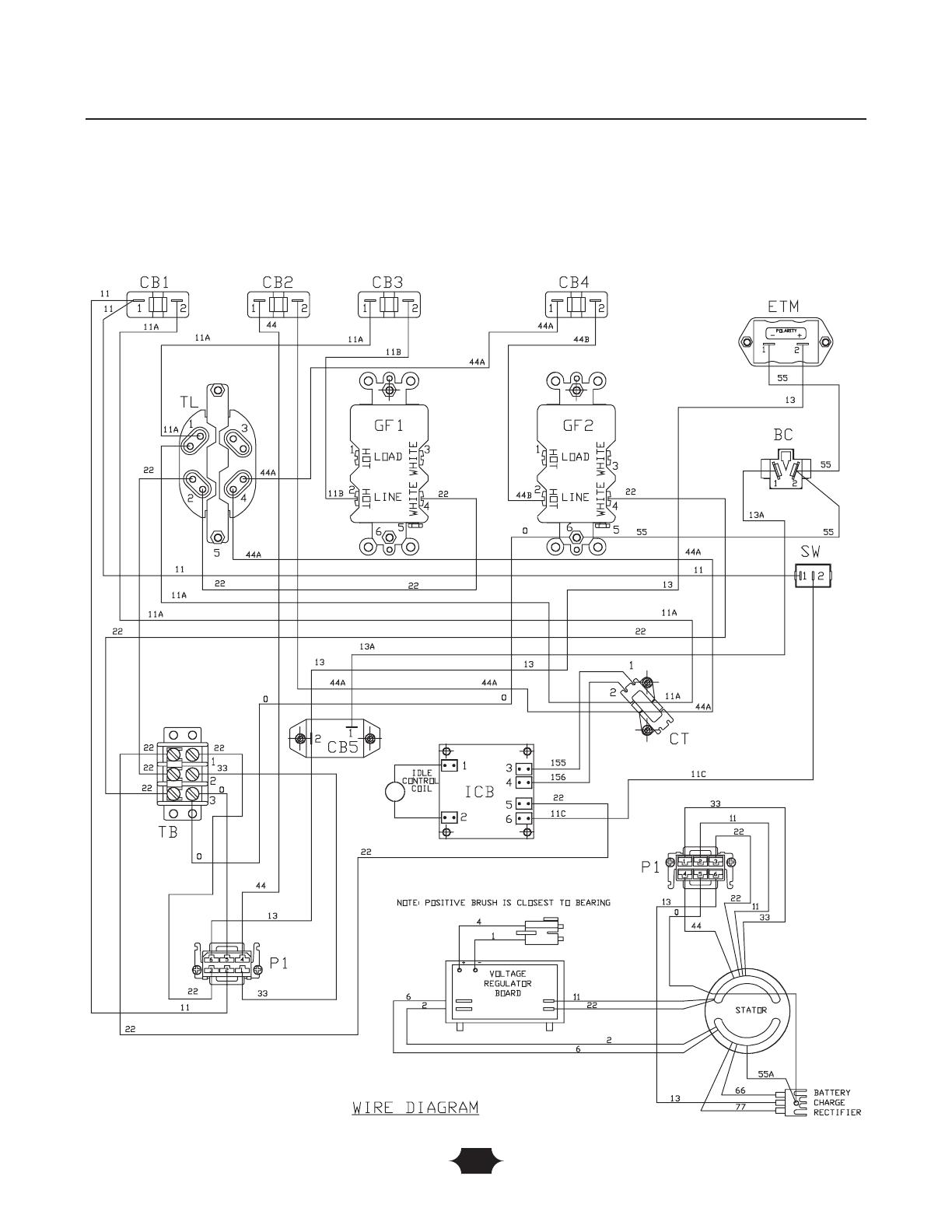
WIRING DIAGRAM
Wiring Diagram
20
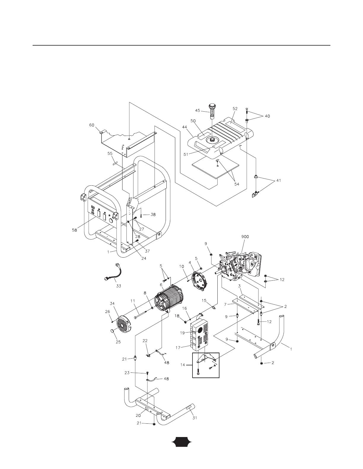
EXPLODED VIEW – MAIN UNIT
Exploded Views
/