Landan FPD8087 Series Owner's manual
- Category
- Household fans
- Type
- Owner's manual
This manual is also suitable for

Model No. FPD8087**
OWNER'S MANUAL
READ AND SAVE THESE INSTRUCTIONS
The Landan
™
Ceiling Fan
Net Weight 9.91 kg. (21.85 lbs.)

2
Important Safety Instructions
WARNING: To avoid fire, shock and serious personal injury, follow these instructions.
1. Read your owner’s manual and safety information before installing your new fan. Review the accompanying assembly
diagrams.
2. Before servicing or cleaning unit, switch power off at service panel and lock service panel disconnecting means to prevent
power from being switched on accidentally. When the service disconnecting means cannot be locked, securely fasten a
warning device, such as a tag, to the service panel.
3. Be careful of the fan and blades when cleaning, painting, or working near the fan. Always turn off the power to the ceiling
fan before servicing.
4. Do not insert anything into the fan blades while the fan is operating.
5. Do not operate reversing switch until fan blades have come to a complete stop.
Additional Safety Instructions
1. To avoid possible shock, be sure electricity is turned off at the fuse box before wiring, and do not operate fan without
blades.
2. All wiring and installation procedures must satisfy National Electrical Codes (ANSI/ NFPA 70-1999) and Local Codes. The
ceiling fan must be grounded as a precaution against possible electrical shock. Electrical installation should be made or
approved by a licensed electrician.
3. The fan base must be securely mounted and capable of reliably supporting at least 35 lbs. (fan and accessories not to
exceed 35 lbs. or 15.88 kgs.). See page 4 of owner’s manual for support requirements. Consult a qualified electrician if in
doubt.
4. The fan must be mounted with the fan blades at least 7 feet from the floor to prevent accidental contact with the fan blades.
5. Follow the recommended instructions for the proper method of wiring your ceiling fan. If you do not have adequate
electrical knowledge or experience, have your fan installed by licensed electrician.
6. Suitable for use with solid-state speed controls.
WARNING
:
To reduce the risk of fire or electric shock, this fan should only be used with Fan Speed Control Part No.
UC7067RYL, manufactured by Rhine Electronic Co., Ltd.
WARNING
:
TO REDUCE THE RISK OF ELECTRIC SHOCK, THIS FAN MUST BE INSTALLED WITH A GENERAL USE,
ISOLATING WALL CONTROL/SWITCH.
WARNING
:
This product is designed to use only those parts supplied with this product and/or accessories designated
specifically for use with this product. Using parts and/or accessories not designated for use with this product could result in
personal injury or property damage.
WARNING
:
To reduce the risk of personal injury, do not bend the blade bracket (flange or blade holder) when installing the
WARNING
:
Mount to an outlet box marked acceptable for fan support.
brackets, balancing the blades, or cleaning the fan. Do not insert foreign objects in between rotating fan blades.
LIMITED LIFETIME WARRANTY
Extends to the original purchaser of a Fanimation Fan
1. LIMITED LIFETIME MOTOR WARRANTY - If any part of your fan motor fails, due to a defect in materials or workmanship
during the lifetime of the original purchaser, Fanimation will provide the replacement part free of charge, when the defective
fan is returned to our national service center. Proof of purchase is required. Customer shall be responsible for all costs
incurred in the removal or reinstallation and shipping of the product for repairs or replacement.
2. ONE YEAR MOTOR LABOR WARRANTY - If your fan motor fails at any time within one year from the original purchase, due
to defects in materials or workmanship, labor to repair the motor will be provided free of charge at our national service
center. Purchaser will be responsible for labor charges after this one-year period. Customer shall be responsible for all
costs incurred in the removal or reinstallation and shipping of the product for repairs or replacement.
3. If any other part of your fan fails at any time within one year after original purchase, due to a defect in materials or
workmanship, we will repair, or replace, at our option, the defective part free of charge for parts and labor performed at our
national service center.
4. Because of varying climate conditions, this warranty does not cover changes in the finish, including rusting, pitting,
corroding, tarnishing, or peeling.
5. This warranty is void and does not apply to damage from improper installation, neglect, accident, misuse, exposure to
extremes of heat or humidity, or as a result of any modification to the original product.
6. All costs of removal and reinstallation of the fan are the sole responsibility of the owner of the fan and not the store that
sold the fan or Fanimation.
7. Fanimation reserves the right to modify or discontinue any product at any time and may substitute any part under this
warranty.
8. Under no circumstances may a fan be returned without prior authorization from Fanimation. The receipt of purchase must
accompany authorized returns and must be sent freight prepaid to Fanimation. The fan to be returned must be properly
packed to avoid damage in transit; Fanimation will not be responsible for any damage resulting from improper packaging.
9. It is understood that any repair or replacement is the exclusive remedy available from Fanimation. There is no other
expressed or implied warranty. Fanimation hereby disclaims any and all implied warranties, including, but not limited to
those of merchantability and fitness for a particular purpose to the extent permitted by law. Some states do not allow
limitations on implied warranties. Fanimation will not be liable for incidental, consequential, or special damages arising out
of or in conjunction with product use or performance, except as may otherwise be accorded by law. This warranty gives you
special legal rights and you may also have other rights that vary from state to state.
10.A certain amount of wobble is normal and should not be considered a problem or a defect.
Unpacking Instructions . . . . . . . . . . . . . . . . . . . . . . . . . . . . . . .3
Energy Efficient Use of Ceiling Fans . . . . . . . . . . . . . . . . . . . . .4
Electrical and Structural Requirements . . . . . . . . . . . . . . . . . .4
How to Assemble Your Ceiling Fan . . . . . . . . . . . . . . . . . . . . . .5
How to Hang Your Ceiling Fan . . . . . . . . . . . . . . . . . . . . . . . . . .7
How to Wire Your Ceiling Fan . . . . . . . . . . . . . . . . . . . . . . . . . .8
How to Install Your Canopy Housing . . . . . . . . . . . . . . . . . . . .9
How to Assembly the Blades & Light Kit . . . . . . . . . . . . . . . .10
How to Operate Your Ceiling Fan . . . . . . . . . . . . . . . . . . . . . .12
Maintenance . . . . . . . . . . . . . . . . . . . . . . . . . . . . . . . . . . . . . . . .13
How to Clean Your Ceiling Fan Blades . . . . . . . . . . . . . . . . . .13
How to Replace Receiver . . . . . . . . . . . . . . . . . . . . . . . . . . . . .13
Trouble Shooting . . . . . . . . . . . . . . . . . . . . . . . . . . . . . . . . . . . .14
Parts List . . . . . . . . . . . . . . . . . . . . . . . . . . . . . . . . . . . . . . . . . .15
Exploded-View Illustration . . . . . . . . . . . . . . . . . . . . . . . . . . . .16
Table of Contents

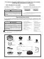
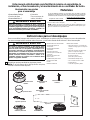
1. Check to see that you have received the following parts:
If you are uncertain of part description, refer to
exploded view illustration.
This Manual Is Designed to Make it as Easy as Possible for You to Assemble,
Install, Operate and Maintain Your Ceiling Fan
Tools Needed for Assembly
• One Phillips head screwdriver
• One stepladder
• Three wire connectors (supplied)
3
Installed Wire Length Wire Size A.W.G.
Unpacking Instructions
For your convenience, check-off boxes are provided next to each step. As each step is completed, place a check
mark in the box. This will insure that all steps have been completed and will be helpful in finding your place should
you be interrupted.
Before assembling your ceiling fan, refer to section
on proper method of wiring your fan (page 4). If you
feel you do not have enough wiring knowledge or
experience, have your fan installed by a licensed
electrician.
Do not install or use fan if any part is damaged or
missing. This product is designed to use only those
parts supplied with this product and/or any
accessories designated specifically for use with this
product by Fanimation. Substitution of parts or
accessories not designated for use with this product
by Fanimation could result in personal injury or
property damage.
WARNING
WARNING
• One wire stripper
• One 1/4” blade
screwdriver
Materials
Wiring outlet box and box connectors must be of type
required by the local code. The minimum wire would be a
3-conductor (2-wire with ground) of the following size:
Up to 50 ft. 14
50-100 ft. 12
Place the parts from the loose parts bags in a small
container to keep them from being lost. If any parts are
missing contact your local retailer.
• Fan Motor Assembly
• Hanger Bracket Assembly
• Hanger Ball / Downrod Assembly
• Ceiling Canopy
• Canopy Screw Cover Assembly
• Blade Holder Set (5)
• Blade Set (5)
• Light Plate Assembly
• LED Down Light Assembly
• Glass
• Remote Hand Held
• Hardware bags:
– Sixteen 3/16-24 x 7.5mm
(blade to blade holder)
Washer Head Screw
– Sixteen 3/16” Fiber Washer
(blade to blade holder)
– Eleven 1/4”-20 x 14mm
(blade arm to motor)
Pan Head Screw
– Phillips Screwdriver, 4”
– Three Wire Connectors
– Balance Kit
– Bag Assembly Safety Cable
Hanger Bracket
Assembly
Hanger Ball / Downrod
Assembly
Fan Motor
Assembly
Ceiling Canopy
Blade Holder Set
Light Plate Assembly LED Down Light
Assembly
Blade Set
Glass
Canopy Screw Cover
Assembly
Remote Hand Held
Hardware Bag

4
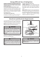
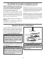
Energy Efficient Use of Ceiling Fans
Ceiling fan performance and energy savings rely
heavily on the proper installation and use of the
ceiling fan. Here are a few tips to ensure efficient
product performance.
Choosing the Appropriate Mounting Location
Ceiling fans should be installed, or mounted, in the
middle of the room and at least 7 feet above the floor
and 18 inches from the walls. If ceiling height allows,
install the fan 8 - 9 feet above the floor for optimal
airflow. Consult your Fanimation Retailer for optional
mounting accessories.
Turn Off When Not in the Room
Ceiling fans cool people, not rooms. If the room is
unoccupied, turn off the ceiling fan to save energy.
Using the Ceiling Fan Year Round
Summer Season: Use the ceiling fan in the
counterclockwise direction. The airflow produced by
the ceiling fan creates a wind-chill effect, making you
“feel” cooler. Select a fan speed that provides a
comfortable breeze, lower speeds consume less
energy.
Winter Season: Reverse the motor and operate the
ceiling fan at low speed in the clockwise direction.
This produces a gentle updraft, which forces warm air
near the ceiling down into the occupied space.
Remember to adjust your thermostat when using your
ceiling fan - additional energy and dollar savings
could be realized with this simple step!
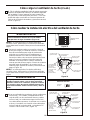
Electrical and Structural Requirements
If your fan is to replace an existing light fixture, turn
electricity off at the main fuse box at this time and
remove the existing light fixture.
Your new ceiling fan will require a grounded electrical
supply line of 120 volts AC, 60 Hz, 15 amp circuit.
The outlet box must be securely anchored and
capable of withstanding a load of at least 50 lbs.
Figure 1 depicts different structural configurations
that may be used for mounting the outlet box.
To avoid fire or shock, follow all wiring instructions
carefully. Any electrical work not described in these
instructions should be done or approved by a
licensed electrician.
Turning off wall switch is not sufficient. To avoid
possible electrical shock, be sure electricity is
turned off at the main fuse box before wiring. All
wiring must be in accordance with National and
Local codes and the ceiling fan must be properly
grounded as a precaution against possible electrical
shock.
WARNING
WARNING
To reduce the risk of fire, electrical shock, or
personal injury, mount fan to outlet box marked
acceptable for fan support of 15.88 kg (35 lbs) or less.
Use screws supplied with outlet box. Most outlet
boxes commonly used for support of light fixtures
are not acceptable for fan support and may need to
be replaced. Consult a qualified electrician if
in doubt.
WARNING
Figure 1
CEILING
2" x 4"
CEILING JOIST
OUTLET BOX

5
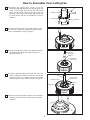
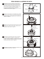
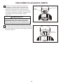
How to Assemble Your Ceiling Fan
1. Remove the hanger ball portion from the
downrod/hangerball assembly by loosening the set
screw in the hanger ball until the ball falls freely
down the downrod. Remove the pin from the
downrod, then remove the hanger ball. Retain the
pin and hanger ball for reinstallation in Step 4
(Figure 1).
3. Loosen
2. Loosen the two screws in the motor coupler cover
then remove it. Retain the screws and motor coupler
cover for installation in Step 5 (Figure 2).
the two set screws in the downrod support.
Route black and white lead wires through the
downrod (Figure 3).
4. Position downrod support and align the clevis pin
holes in both parts. Install the clevis pin and secure
with the hairpin clip. Tighten the two set screws
and locking nuts in the downrod support (Figure 4).
5. Route wires through motor coupler cover assembly
and tight the two screws from the motor assembly
(Figure 5).
Figure 1
PIN
SET SCREW
DOWNROD
HANGER BALL
BLACK AND
WHITE LEADS
DOWNROD
SET SCREWS AND
LOCKING NUTS(2)
Figure 3
Figure 2
Figure 5
DOWNROD
DOWNROD SUPPORT
SCREWDRIVER
SET SCREWS AND
LOCKING NUTS (2)
Figure 4
CLEVIS PIN
HAIRPIN CLIP

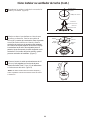
6. Route wires through canopy screw cover and
canopy
(Figure 6).
CANOPY
DOWNROD
SET SCREW
PIN
GROOVE
HANGER BALL
7. Reinstall the hanger ball on the downrod as
follows.Route the three 80-inch wires through the
hanger ball. Position the pin through the two holes
in the downrod and align the hanger ball so the pin
is captured in the groove in the top of the hanger
ball. Pull the hanger ball up tight against the pin.
Securely tighten the set screw in the hanger ball.
A loose set screw could create fan wobble
(Figure 7).
Figure 7
MOTOR COUPLER
COVER ASSEMBLY
CANOPY SCREW COVER
CANOPY
BLACK &
WHITE LEADS
Figure 6
6
How to Assemble Your Ceiling Fan (Cont’d)
8. Cut off excess lead wire approximately 6 to 9
inches above top of the top of the downrod. Strip
insulation off 1/2-inch from the end of each lead
wire (Figure 8).
NOTE:
All set screws must be checked, and retightened
where necessary, before installation.
Figure 8

7
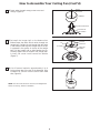
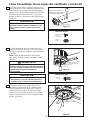
How to Hang Your Ceiling Fan
NOTE: If you are not sure if the outlet box is grounded,
contact a licensed electrician for advise, as it must be
grounded for safe operation.
WARNING
The fan must be hung with at least 7’ of clearance
from floor to blades. (Figure 10)
Figure 10
CEILING
FLOOR
NO LESS
THAN
7 FEET
WARNING
To avoid possible fire or shock, be sure electricity is
turned off at the main fuse box before hanging.
(Figure 9)
Figure 9
MAIN FUSE BOX
WOOD MEMBER
(2” X 4” APPROX.)
CEILING JOIST
CEILING
JUNCTION
BOX
HANGER BRACKET
CEILING
SUPPORT
CABLE
Figure 11
1. Securely attach the hanger bracket to the outlet box
using the outlet box screws and washers supplied with
the outlet box. (Figure 11)
WARNING
The outlet box must be securely anchored. Hanger
bracket must seat firmly against outlet box. If the
outlet box is recessed, remove wall board until bracket
contacts box. If bracket and /or outlet box are not
securely attached, the fan could wobble or fall.
2. Drill a ¼” pilot hole into the building structure to
prevent splitting or cracking with installation of the lag
bolt. Using the ” x 2” lag bolt and flat washer, attach
safety cable to ceiling joist or wood structural member.
The lag bolt will pass through the flat washer, safety
cable loop, and into the building structure. (Figure 11)
NOTE: Ceiling support cable cannot be secured to
junction box only, it must be directly secured to ceiling
joist or structural member using the ” x 2” lag bolt
and flat washer. (Figure 11)
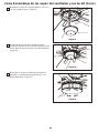
3. Make sure the electrical supply wires, including
the hanger bracket grounding wire and safety cable
are pulled through the downrod, between the hanger
bracket and the junction box so that electrical
connections can be made later.
4. Carefully lift the fan and seat the downrod/hanger ball
assembly on the hanger bracket that was just attached to
the outlet box. Be sure the groove in the ball is lined up
with tab on the hanger bracket (Figure 12)
WARNING
Failure to seat tab in groove could cause damage to
electrical wires and possible shock or fire hazard.
WARNING
To avoid possible shock, do not pinch wires between
the hanger ball assembly and the hanger bracket.
5. Attach the safety cable to ceiling support cable. Slide
cable clamp onto safety cable (from fan). Place the end
of cable through the loop of ceiling support cable. Pull as
much cable through loop as possible. Feed end of cable
into clamp hole and firmly tighten screw (Figure 12).
X 1
HARDWARE USED:
Figure 12
TAB
NOTE: SUPPLY WIRES AND FAN
WIRES OMITTED FOR CLARITY
DOWNROD/HANGER
BALL ASSEMBLY
ATTACH SAFETY
CABLE TO CEILING
SUPPORT CABLE
CEILING SUPPORT
CABLE CLAMP
W/SCREW

8
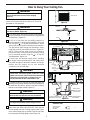
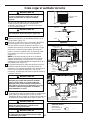
How to Wire Your Ceiling Fan
To avoid possible electrical shock, be sure electricity
is turned off at the main fuse box before hanging
(Figure 13).
WARNING
MAIN FUSE BOX
Figure 13
NOTE:
If you are not sure if the outlet box is
grounded, contact a licensed electrician for advice, as
it must be grounded for safe operation.
Figure 14
1. Connect the green grounding lead from the
downrod/hanger ball assembly and the green
grounding lead from the hanger bracket to the supply
grounding conductor (this may be a bare wire or wire
with green colored insulation). Securely connect wires
with wire connectors. Securely connect the white fan
motor wire to the white supply (neutral) wire using
wire connector. Securely connect the black fan motor
wire to the black supply wire using wire connector
(Figure 14).
Green Wire
from Supply
(Ground)
White Wire
from Supply
White Wire
from Fan
Green Wire
from Hanger
Bracket (Ground)
Green Wire
from Hanger
Ball (Ground)
Listed
Outlet Box
Household
Supply
Black Wire
from Supply
Black Wire
from Fan
x 3WIRE
CONNECTORS
HARDWARE USED:
NOTE:
If you feel that you do not have enough electrical
wiring knowledge or experience, have your fan installed
by a licensed electrician.
Check to see that all connections are tight, including
ground, and that no bare wire is visible at the wire
connectors except for the ground wire. Do not
operate fan until the blades are in place. Noise and
motor damage could result.
WARNING
Figure 15
Green Wire
from Supply
(Ground)
White Wire
from Supply
White Wire
from Fan
Green Wire
from Hanger
Bracket (Ground)
Green Wire
from Hanger
Ball (Ground)
Listed
Outlet Box
Household
Supply
Black Wire
from Supply
Black Wire
from Fan
2. After connections have been made, turn leads
upward and carefully push leads into the outlet
box, with the white and green leads to one side
of the box and the black leads toward the
other side. The wires should be spread apart
with the grounded conductor and the
equipment-grounding conductor on one side of
the outlet box and the ungrounded conductor
on the other side of the outlet box. (Figure 15)

9
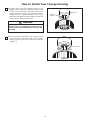
1. Remove one of the two shoulder screws in the
hanger bracket. Loosen the second shoulder screw
without fully removing it. Assemble canopy by
rotating key slot in canopy over shoulder screw in
hanger bracket. Tighten shoulder screw. Fully
assemble and tighten second shoulder screw that
was previously removed (Figure 16).
2. Securely attach and tighten the canopy screw
cover over the shoulder screws in the hanger
bracket utilizing the keyslot twist-lock feature
(Figure 17).
How to Install Your Canopy Housing
To avoid possible fire or shock, make sure that the
electrical wires are completely inside the canopy
housing and not pinched between the housing and
the ceiling.
WARNING
CANOPY
SHOULDER
SCREWS (2)
Figure 16
CANOPY COVER
Figure 17

10
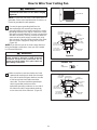
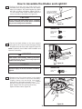
How to Assemble the Blades and Light Kit
x 15
x 15
FIBER WASHER
3/16-24 x 7.5mm
WASHER HEAD
SCREWS
HARDWARE USED:
BLADE
3/16-24 x 7.5mm WASHER
HEAD SCREW AND FIBER
WASHER (3 each per blade)
BLADE HOLDER
Figure 18
BLADE HOLDER
1/4-20 x 14mm SCREWS
(2 per assembly)
Figure 19
Figure 20
1. Position the blade over the blade holder with
threaded posts showing. Make sure the bottom
edge of the blade is fully seated against the blade
arm. With a Phillips screwdriver, tighten 3/16-24 x
7.5 mm washer head screws and fiber washers to
secure the blade to the blade arm (Figure 18).
2. Secure the blade holders to the motor support
using the 1/4-20 x 14 mm screws through the holes
located on the side of the motor support (Figure 19).
NOTE:
Periodically check blade holder hardware and
resecure if necessary.
3. Remove one of the three screws in the support
bracket at the bottom of the motor assembly.
Slightly loosen the remaining two screws.
Assemble the light plate assembly to the
support
bracket using the two key slots in the socket
plate. Replace the third screw and securely
tighten all three screws (Figure 20).
Do not connect fan blades until the fan is completely
installed. Installing the fan with blades assembled
may result in damage to the fan blades.
CAUTION
To reduce the risk of electric shock, disconnect the
electrical supply circult to the fan before installing
light kit.
CAUTION
To reduce the risk of personal injury, do not bend the
blade holders when installing, balancing the blades
or cleaning the fan. Do not insert foreign objects in
between the rotating blades.
WARNING
SCREWS (3)
LIGHT PLATE
ASSEMBLY
x 10
1/4-20 x 14mm
SCREWS
HARDWARE USED:
MOTOR
ASSEMBLY

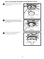
5. Remove three screws in the light plate assembly.
Assemble the LED down light assembly to the light
plate assembly using the three screws and securely
tighten. (Figure 22)
11
How to Assemble the Blades and Light Kit (Cont’d)
LED DOWN LIGHT
ASSEMBLY
Figure 21
Figure 22
4. Connect the 2-pin connector from the LE D down
assembly light to 2-pin connector from motor
assembly. (Figure 21)
Figure 23
6. Secure the glass to the light plate assembly
by twisting in a clockwise direction.
Do not over-tighten. (Figure 23)
GLASS
LIGHT PLATE
ASSEMBLY
MOTOR ASSEMBLY
SCREWS (3)
LED DOWN LIGHT
ASSEMBLY

12
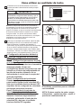
How to Operate Your Ceiling Fan
MAIN FUSE BOX
Figure 24
Figure 27
1. Restore electrical power to the outlet box by turning
the electricity on at the main fuse box (Figure 24).
Check to see that all connections are tight, including
ground, and that no bare wire is visible at the wire
connectors, except for the ground wire. Do not
operate fan until the blades are in place. Noise and
fan damage could result.
WARNING
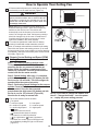
2. To make fan operational, install 23A/12V battery
(included) in hand-held remote transmitter, with fan
power off, arrange code switches to desired code setting.
Then follow the remote code setting process. (If not used
for long periods of time, remove battery to prevent damage
to transmitter). Store the remote away from excessive heat
or humidly (Figure 25).
4. The remote buttons instruct as below:
I = minimum speed II = low speed
III = medium low speed IV = medium speed
V = medium high speed VI = high speed
Button:
This button turns the fan off.
Reverse button (back of remote):
This button is to control fan direction.
Down Light button:
The button is to control light, Infinite light levels
are available by holding the light on/off button
(Figure 27).
Up Light button /
Fan speed:
NOTE:
Receiver in controllers system features an
automatic learning function. There are no frequency
switches on the receiver unit. The receiver will
automatically scan the frequency from the hand held
control if an changes are made. the frequency settings
should be changed only in the case of interference or
if multiple ceiling fans with the same type of control
system are installed in the same structure.
NOTE: If you want to change the blades: turn
the off→ change the blades →turn the power
on →replay the power setting process.
3. Remote Control Setting and Speed (RPM)
Setting Process :
Step 1: Set code switches to desired code.
Turn power on to the fan. Within 60 seconds of
powering the fan on, press and hold the set
button inside the battery compartment of the
remote for 5 seconds. This will synchronize the
control with the fan motor receiver.
Step 2: Speed Setting: After step 1 is complete,
press/release the high speed (VI) button and allo
fan to run for 120 seconds. This will configure th
speeds within the motor electronics.
Step 3: Performing Speed Settings for the reverse
speeds: Press/release the reverse button on the
remote control. Once fan has reversed,
press/release the high speed (VI) button and allo
the fan to run for 120 seconds. (Figure 26).
Now the fan is ready for normal use.
Figure 26
Step 1
Step 3
Step 2
Figure 25

13
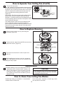
How to Operate Your Ceiling Fan (Cont’d)
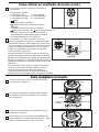
How to Replace Receiver
Maintenance
1. Periodic cleaning of your new ceiling fan is the only
maintenance that is needed. When cleaning, use
only a soft brush or lint free cloth to avoid
scratching the finish. Abrasive cleaning agents are
not required and should be avoided to prevent
damage to finish.
Do not use water when cleaning your ceiling fan.
It could damage the motor or the finish and create
the possibility of electrical shock.
CAUTION
Periodic light dusting of the blades is recommended.
A feather duster will work best.
How to Clean Your Ceiling Fan Blades
Avoid using water, cleansers, or harsh rags, which
can warp and ruin the finish.
1. Remove motor coupler cover by unscrewing the
two screws. (Figure 29)
2. Unplug antenna, signal wire and 9-PIN connector then
replace new receiver. (Figure 30)
3. Tight the two screws from the motor coupler cover.
(Figrue 31)
4. After installing new receiver to your fan, operate the
remote “Code Setting” process on “How to operate your
ceiling fan” Step 3 again.
Figure 28
Code Switches
Reverse
Button
Figure 29
Motor Coupler
Cover
Figure 31
Figure 30
Receiver
Signal Wire
9-Pin
Antenna
connector
5. “D” and “ON” dip switch:
The “ON” selection is the light dimmable selection and is to
be used with all bulbs other than CFL. The “D” selection is
the light on only (no dimming function) and is to be used
with CFL bulbs (as CFL bulbs cannot be dimmed). The
receiver provides the following protective function:
(Figure 28)
Lock position: The DC motor has a built-in safety feature
against blade obstruction against obstruction during
operation. If something obstructs the fan blades the motor
will stop operating after 30 seconds of interruption. Please
remove obstacles and reset.
Over 80W protection: When the receiver detects motor
power consumption which is greater than 80W, the
receiver power will shutdown and fan operation will cease.
Disconnect the power supply and after 5 seconds return-
power on to the fan.

14
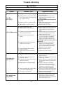
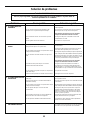
Trouble Shooting
For your own safety turn off power at fuse box or circuit breaker before trouble shooting your fan.
WARNING
!
Trouble Probable Cause Suggested Remedy
1.FAN WILL
NOT START
1. Check main and branch circuit fuses
or circuit breakers.
2. Check line wire connections to fan
and switch wire connections in the
switch housings.
CAUTION: Make sure main power is
turned off !
3. Make sure reversing switch position is
all the way to one side.
4. Replace with fresh battery.
1. Fuse or circuit breaker blown.
2. Loose power line connections to the
fan, or loose switch wire connections
in the switch housing.
3. Reversing switch in neutral position.
4. Dead battery in remote control.
2.FAN SOUNDS NOISY
1. Attach blades to fan before operating.
2. Check to make sure all screws in
motor housing are snug (not over-
tight).
3. Check to make sure the screws which
attach the fan blade holders to the
motor flywheel are tight.
4. Check to make sure wire connectors
in switch housing are not rattling
against each other or against the
interior wall of the switch housing.
CAUTION: Make sure main power is
turned off !
5. Some fan motors are sensitive to
signals from solid-state variable
speed controls. Solid-state controls
are not recommended, choose an
alternative control method.
6. Tighten screws securely.
7. Tighten set screw securely.
1. Blades not attached to fan.
2. Loose screws in motor housing.
3. Screws securing fan blade holders to
motor flywheel are loose.
4. Wire connectors inside housing
rattling.
5. Motor noise caused by solid state
variable speed control.
6. Screws holding blades to blade
holders are loose.
7. Lower housing support set screw
loose.
3.FAN WOBBLES
EXCESSIVELY
1. Tighten both setscrews securely in
downrod support.
2. Tighten the setscrew in the downrod/
hanger ball assembly.
3. Check to be sure screws which attach
the fan blade holders to the flywheel
are tight.
4. Check to be sure the fan blade
holders seat firmly and uniformly to
the surface of the motor housing.
If holders are seated incorrectly,
loosen the screws and retighten.
5. Tighten the hanger bracket screws to
the outlet box, and secure outlet box.
6. Balance blades using balance kit
provided in hardware bag.
1. Setscrew in downrod support is loose.
2. Setscrew in downrod/hanger ball
assembly is loose.
3. Screws securing fan blade holders to
motor hub are loose.
4. Blade holders not seated properly.
5. Hanger bracket and/or ceiling outlet
box is not securely fastened.
6. Fan blades out of balance.
4.NOT ENOUGH AIR
MOVEMENT
1. If possible, consider using a longer
downrod. For example, use a 12”
downrod instead of the 4½” downrod
that comes with your fan.

15
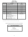
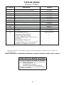
Parts List
Model No. FP8087**
1 Hanger Bracket Assembly AP255BL
ADRAC1-45**
PG154**
Hanger Ball-Downrod Assembly
2
Ceiling Canopy3
4 Canopy Screw Cover
AP260**
AP808704**
AP808705**
AP808706**
AP808708
P808709**
TR31
AMA8087**Fan Motor Assembly5
Blade Holder Set6
Blade Set7
Light Plate Assembly8
9
10
11
13
LED Down Light Assembly
Glass
Remote Hand Held
RECAN125S
12
Receiver
HDWFPD8087**
—
—
—
—
—
—
—
—
——
HOW TO ORDER REPAIR PARTS
When ordering repair parts, always give the following information:
• Part Number
• Part Description
• Fan Model Number
Contact your retail store for repair parts.
Before discarding packaging material, be certain all parts have been removed.
** Insert FINISH CODES (Refer to fan model number located on downrod support)
Reference # Description Part #
Balance Kit (BALKT)
Wire Connectors (3)
Bag Assembly Safety Cable
4” Philips Screwdriver
¼”–20 x 14mm Phillips Screws with
Lockwashers (11 pcs)
3/16”–24 x 7.5 mm Washer Head Screws
Washers (16 pcs)
with Fiber

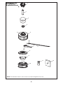
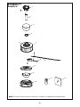
16
NOTE:
The illustration shown is not to scale or its actual configurations may vary.
1
2
3
4
* *7808DPF
Exploded-View
5
12
6
10
11 13
9
7
8

Copyright 2010 2010/11
10983 Bennett Parkway
Zionsville, IN 46077
Toll Free (888) 567-2055
FAX (866) 482-5215
Outside U.S. call (317) 733-4113
Fanimation Visit Our Website www.fanimation.com

The Landan
™
Ventilador de techo
Peso neto 9.91 kg (21.85lb)
MANUAL DEL PROPIETARIO
LEA Y GUARDE ESTAS INSTRUCCIONES
Modelo N.º FPD8087**
Page is loading ...
Page is loading ...
Page is loading ...
Page is loading ...
Page is loading ...
Page is loading ...
Page is loading ...
Page is loading ...
Page is loading ...
Page is loading ...
Page is loading ...
Page is loading ...
Page is loading ...
Page is loading ...
Page is loading ...
Page is loading ...
Page is loading ...
-
 1
1
-
 2
2
-
 3
3
-
 4
4
-
 5
5
-
 6
6
-
 7
7
-
 8
8
-
 9
9
-
 10
10
-
 11
11
-
 12
12
-
 13
13
-
 14
14
-
 15
15
-
 16
16
-
 17
17
-
 18
18
-
 19
19
-
 20
20
-
 21
21
-
 22
22
-
 23
23
-
 24
24
-
 25
25
-
 26
26
-
 27
27
-
 28
28
-
 29
29
-
 30
30
-
 31
31
-
 32
32
-
 33
33
-
 34
34
-
 35
35


Landan FPD8087 Series Owner's manual
- Category
- Household fans
- Type
- Owner's manual
- This manual is also suitable for
Ask a question and I''ll find the answer in the document
Finding information in a document is now easier with AI
in other languages
Other documents
-
Fanimation Edgewood Standard TF100 Owner's manual
-
-
-
-
-
-
-
-
-